Configuring External Connectivity

Configuring Google Cloud Site Connectivity Workflow

The following sections describe how to configure Google Cloud sites infra, intersite connectivity, and a simple deployment use case. The workflow includes:

  • Configuring general infra settings, such as adding the on-premises IPN devices as external devices in Nexus Dashboard Orchestrator and establishing external connectivity from google cloud site to those devices

  • Configuring and deploying external VRFs in the Google Cloud site's Infra tenant

  • Configuring intersite connectivity from your Google Cloud site to an on-premises site and manually configuring any on-premises sites connectivity to the Google Cloud site

  • Configuring intersite connectivity between your Google Cloud site and other cloud sites like AWS/Azure

  • Configuring route leaking in the external VRFs to enable routing between sites

  • Creating or importing a user tenant and EPGs and applying contracts to enable communication between sites

Creating External VRFs in Infra Tenant

You can create a single schema where you will define the external VRFs for all cloud sites in your multi-Site domain. However, since you may want to deploy different VRFs for each cloud site, you must create separate templates for each cloud site you have because templates cannot be shared across different cloud sites.

Following sections will introduce you to the new type of template and will walk you through the process of adding external VRFs. In the schema, create new template for Google Cloud site, use cloud local template, assign the template to the Google Cloud site.

You will have an option to a new type of template which is called Cloud Local.

This type of template cannot be stretched to multiple sites. It supports and allow all types of cloud sites. However, no more than one site can be attached to this template. There is another restriction regarding this template which is some of the objects should be only from within the tenant, Like VRF etc.

The following section describes how to create an external VRF which will be used to establish connectivity to an external devices' subnets. You can follow the provided steps to provision an external VRF to a cloud site.

Procedure


Step 1

Log in to the Cisco Nexus Dashboard Orchestrator GUI.

Step 2

In the Main menu, select Application Management > Schemas.

Step 3

Create a new schema and templates or select an existing schema where you will deploy the templates associated to the Infra tenant containing the external VRFs definition.

You can create a separate schema specifically for this use case, where you will define all templates associated to the Infra tenant and containing the external VRFs providing the connectivity to the external devices.

When creating the external VRF templates:

  • You must use separate templates for different types of cloud sites (AWS, Azure or Google Cloud).

  • You must choose the Cloud Local template type.

  • You must map the template to the infra tenant or the VRFs cannot be used for external connectivity.

  • You can use the same VRF name in both templates. We will use extVrf1 for the examples in this document.

Step 4

In the main pane, select +Create Object > VRF.

Step 5

Provide the Display Name for the VRF.

You can leave all other options at default values.

Note 

In the VRF's site local properties, do not attach this VRF to any regions. Any VRF that is created in the Infra tenant and is not attached to any region is treated as an external VRF and can be used for this use case.

Step 6

Assign the template that contains your external VRF to one or more cloud sites from which you will establish external connectivity.

Remember that you must assign the template only to one type of cloud sites (AWS, Azure or Google Cloud).

Step 7

Deploy the templates to create the external VRF in the cloud sites.


Configuring Inter-site Connectivity Between Google Cloud Site and On-Premises Sites

The following sections describe how to configure connectivity between your Google Cloud site and an on-premises site. If you want to configure connectivity between two cloud sites, see Configuring Intersite Connectivity Between Google Cloud Site and Other Cloud Sites.

Adding External Devices

If you do not plan to establish intersite connectivity between you Google Cloud site and an on-premises site, you may skip this section. This section describes how to provide information about your external devices to your Nexus Dashboard Orchestrator in the Orchestrator's Site Connectivity page.


Note

The following steps focus on the configurations required for this specific use case. Detailed information about all infra configuration settings is available in Cisco Nexus Dashboard Orchestrator Configuration Guides.


Procedure


Step 1

Log in to the Cisco Nexus Dashboard Orchestrator GUI.

Step 2

In the left navigation menu, select Infrastructure > Site Connectivity.

Step 3

In the main pane, click Configure .

Step 4

In the left sidebar, select General Settings.

Step 5

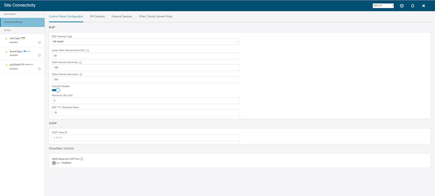
Provide the External Devices information.

This step describes how to provide information about any external devices to which you want to configure connectivity from your cloud sites, for more information regarding this process, see Configure General Infra Settings.

  1. Select the External Devices tab.

  2. Click Add External Device.

    The Add External Device dialogue will open.

  3. Provide the Name, IP Address, and BGP Autonomous System Number for the device.

    The IP address you provide will be used as peer address for the Cloud APIC CSRs or Google Cloud native router's VPN gateway, not the device's management IP addres. The connectivity will be established over public Internet using IPsec.

  4. Click Save, to save the device information.

  5. Repeat this step for any additional external devices you want to add.

Step 6

Enter the necessary information in the IPSec Tunnel Subnet Pools area.

By default, a subnet pool of 169.254.0.0/16 is populated to create the IPsec tunnels between the Google cloud and other cloud sites (AWS/Azure). You can delete the existing subnet pool and add additional subnet pools, if necessary. The subnets used for the IPSec Tunnel Subnet Pools entry must be common /30 CIDRs from the 169.254.0.0/16 block. For example, 169.254.7.0/24 and 169.254.8.0/24 would be acceptable entries for the subnet pools in this field. Click the check mark after you have entered in the appropriate subnet pools.

The following subnets are reserved and cannot be used for any tunnels:

  • 169.254.0.0/30

  • 169.254.1.0/30

  • 169.254.2.0/30

  • 169.254.3.0/30

  • 169.254.4.0/30

  • 169.254.5.0/30

  • 169.254.112.0/24

  • 169.254.113.0/24

  • 169.254.114.0/24

  • 169.254.169.252/30

There are two types of subnet pools that you can provide here:

  • External Subnet Pool—used for connectivity between cloud site router and other sites (cloud or on-premises).

    These are large global subnet pools that are managed by Nexus Dashboard Orchestrator. The Orchestrator, creates smaller subnets from these pools and allocates them to sites to be used for inter-site IPsec tunnels and external connectivity IPsec tunnels.

    For AWS/Azure, you will have to provide at least one external subnet pool if you want to enable external connectivity from one or more of your cloud sites. However, For Google Cloud, you can leave the poolname blank (unselected) when configuring external device connectivity. In this case Nexus Dashboard Orchestrator will allocate a /24169.254.0.0/16 from the subnet (from the top of the range, ie. it will be 169.254.255.0/24 etc).

  • Site-Specific Subnet Pool—used for connectivity between cloud site router and external devices.

    These subnets can be defined when the external connectivity IPsec tunnels must be in a specific range. For example, where a specific subnet is already being used to allocate IP addresses to the external router and you want to continue using those subnets for IPsec tunnels for Nexus Dashboard Orchestrator and cloud sites. These subnets are not managed by the Orchestrator and each subnet is assigned to a site in its entirety to be used locally for external connectivity IPsec tunnels.

    You will assign a name to a site-specific subnet pool, such as 169.254.0.0/24, which you can then use when configuring the external devices.

    If you do not provide any named subnet pools but still configure connectivity between cloud site router and external devices, the external subnet pool will be used for IP allocation to the IPsec tunnels established between cloud site router and external devices.

Note 

The minimum mask length for both subnet pools is /24.

To add one or more External Subnet Pools:

  1. Select the IPsec Tunnel Subnet Pools tab.

  2. In the External Subnet Pool area, click +Add IP Address to add one or more external subnet pools.

    This subnet will be used to address the IPsec tunnel interfaces and loopbacks of the Cloud Routers used for on-premises connectivity, which you previously configured in the Cloud APIC for inter-site connectivity in earlier Nexus Dashboard Orchestrator releases.

    The subnets must not overlap with other on-premises TEP pools, should not begin with 0.x.x.x or 0.0.x.x, and should have a network mask between /16 and /24, for example 10.12.0.0/16.

  3. Click the check mark icon to save the subnet information.

  4. Repeat these substeps for any additional subnet pools you want to add.

To add one or more Site-Specific Subnet Pool:

  1. Select the IPsec Tunnel Subnet Pools tab.

  2. In the Named Subnet Pool area, click +Add IP Address to add one or more external subnet pools.

    The Add Named Subnet Pool dialogue will open.

  3. Provide the subnet Name.

    You will be able to use the subnet pool's name to choose the pool from which to allocate the IP addresses later on, for example extSubPool1.

  4. Click +Add IP Address to add one or more subnet pools.

    The subnets must have a network mask between /16 and /24and not begin with 0.x.x.x or 0.0.x.x, for example 10.181.0.0/16.

  5. Click the check mark icon to save the subnet information.

    Repeat the steps if you want to add multiple subnets to the same named subnet pool.

  6. Click Save to save the named subnet pool.

  7. Repeat these substeps for any additional named subnet pools you want to add.


Establishing Intersite Connectivity Between Google Cloud Site and On-Premises Sites

Before you begin, you must have:

  • Created and deployed the external VRFs in your Google Cloud site, as described in Creating External VRFs in Infra Tenant.

  • Added one or more external devices, as described in Adding External Devices.


    Note

    Before configuring the external connectivity, you can refresh across all the sites in Fabric Connectivity Infra page and deploy to make sure that all CSRs for AWS/AZure and cloud routers for Google Cloud sites are reflected correctly in Nexus Dashboard Orchestrator.


Before you begin

This section describes how to configure site-specific Infra settings for Cloud APIC sites. Before starting make sure that you have:
  • Created and deployed the external VRFs in your Google Cloud site, as described in Creating External VRFs in Infra Tenant.

  • Added one or more external devices, as described in Adding External Devices.


    Note

    Before configuring the external connectivity, you can refresh across all the sites in Fabric Connectivity Infra page and deploy to make sure that all CSRs for AWS/AZure and cloud routers for Google Cloud sites are reflected correctly in Nexus Dashboard Orchestrator.


Procedure


Step 1

In the left pane of the Fabric Connectivity Infra page, under Sites, select a specific cloud site.

This is the site from which you want to establish connectivity to an external device.

Step 2

Provide External Connectivity information.

You must complete this step to provide connectivity information to the external devices as part of this use case configuration.

  1. In the right <Site> Settings pane, select the External Connectivity tab.

  2. Click Add External Connection.

    The Add External Connectivity dialog will open.

  3. From the VRF dropdown, select the VRF you want to use for external connectivity.

    This is the VRF (extVrf1) which will be used to leak the cloud routes and which you already created.

  4. Click +Add External Device.

  5. From the Name dropdown in the External Devices section, select the external device.

    This is the external device which you added in the General Settings > External Devices list during general infra configuration and must already be defined.

  6. For the Tunnel IKE Version, IKE-V2 will be selected. As of this release, only IKE-V2 is supported.

  7. (Optional) From the Tunnel Subnet Pool dropdown, choose one of the site-specific subnet pools.

    Site-specific subnet pools are used to allocate IP addresses for IPsec tunnels between cloud site router and external devices. If you do not provide any Site-Specific Subnet Pool subnet pools here, the External Subnet Pool subnet pool will be used for IP allocation.

    Providing a dedicated subnet pool for external device connectivity is useful for cases where a specific subnet is already being used to allocate IP addresses to the external router and you want to continue to use those subnets for IPsec tunnels for Nexus Dashboard Orchestrator and cloud sites.

  8. (Optional) In the Pre-Shared Key field, provide the custom keys you want to use to establish the tunnel.

    If you do not provide a pre-shared key, Cloud APIC will generate one automatically on the cloud site router.

  9. If necessary, repeat the previous substeps for any additional external devices you want to add for the same external connection (same external VRF).

  10. If necessary, repeat this step for any additional external connections (different external VRFs).

    Note that there's a one-to-one relationship for tunnel endpoints between cloud site router and external devices, so while you can create additional external connectivity using different external VRFs, you cannot create additional connectivity to the same external devices.


Deploying Configuration to External Devices

While the previous section described how to deploy infra configuration to the cloud sites' Cloud APICs to enable connectivity from the cloud sites to the external devices, this section describes how to enable connectivity from the external device to the cloud sites.

Procedure


Step 1

Gather the necessary information that you will need to enable connectivity from the external device.

You can get the required configuration details using either the Deploy & Download External Device Config files or the Download External Device Config files option in Nexus Dashboard Orchestrator as part of the procedure.

When you download the configuration files:

  • The number of files will match the number of sites that have external connectivity.

  • The file name affixes will match the site IDs.

    For example, <...>-2.config indicates the file is for a site with Site ID 2. The site ID is listed in each site's Site Connectivity page in the Nexus Dashboard Orchestrator GUI.

Step 2

Log into the external device.

Step 3

Configure the tunnels and BGP from the external device to the cloud router.

When configuring external devices:

  • Depending on the specific requirements, the external subnets may or may not be in the same VRF with the tunnel interfaces

    If the external subnets are in different VRFs then proper route leaking must be configured on the external device

    Note 

    Note that the configuration downloaded from Nexus Dashboard Orchestrator only allows to establish IPsec and BGP connectivity. It does not provide any information on the route-leaking configuration within the external device itself.

  • Once the external subnets are advertised to the cloud site router, Nexus Dashboard Orchestrator provisions the route leaking configuration to select the subnets to be imported into the user tenant VRF.

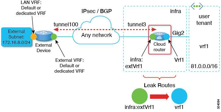
  • The following examples assume BGP configuration is done in the external VRF (extVrf1) and the external subnets as well as tunnel interfaces on the external device are part of the same VRF.

The following example shows how to configure a single IPsec tunnel (Tunnel100) from an external device (in this case ASR1K) to a CSR:

Example:

crypto ikev2 proposal ikev2-1 
 encryption aes-cbc-256 aes-cbc-192 aes-cbc-128
 integrity sha512 sha384 sha256 sha1
 group 24 21 20 19 16 15 14 2
!
crypto ikev2 policy ikev2-1 
 proposal ikev2-1
!
crypto ikev2 keyring keyring-ifc-7
 peer peer-ikev2-keyring
  address 35.220.81.45
  pre-shared-key 163988519666274287497025544399329641924
 !
crypto ikev2 profile ikev-profile-ifc-7
 match address local interface GigabitEthernet1
 match identity remote address 35.220.81.45 255.255.255.255 
 identity local address 20.92.217.94
 authentication remote pre-share
 authentication local pre-share
 keyring local keyring-ifc-7
 lifetime 3600
 dpd 10 5 periodic
 !
crypto ipsec transform-set ikev-transport-ifc-7 esp-gcm 256 
 mode tunnel
 !
crypto ipsec profile ikev-profile-ifc-7
 set transform-set ikev-transport-ifc-7 
 set pfs group14
 set ikev2-profile ikev-profile-ifc-7
 tunnel protection ipsec profile ikev-profile-ifc-7
 !
interface Tunnel100
 description To GCP VPN
 vrf forwarding wanVrf
 ip address 169.254.0.14 255.255.255.252
 ip mtu 1400
 ip tcp adjust-mss 1400
 tunnel source GigabitEthernet1
 tunnel mode ipsec ipv4
 tunnel destination 35.220.81.45
 tunnel protection ipsec profile ikev-profile-ifc-7
end

The following example shows how to configure BGP:

Example:

router bgp 65320
 bgp router-id 172.16.1.1
 bgp log-neighbor-changes
 !
 address-family ipv4 vrf wanVrf
  network 172.16.8.0 mask 255.255.255.0
  network 172.16.9.0 mask 255.255.255.0
  redistribute connected
  neighbor 169.254.0.9 remote-as 65092
  neighbor 169.254.0.9 ebgp-multihop 255
  neighbor 169.254.0.9 activate
  neighbor 169.254.0.13 remote-as 65092
  neighbor 169.254.0.13 ebgp-multihop 255
  neighbor 169.254.0.13 activate
 exit-address-family
!
Step 4

Repeat the previous steps for all external devices.


Configuring Intersite Connectivity Between Google Cloud Site and Other Cloud Sites

The following sections describe how to configure connectivity between two cloud sites. If you want to configure connectivity between a Google Cloud site and an on-premises site, see Configuring Inter-site Connectivity Between Google Cloud Site and On-Premises Sites.


Note

As Google Cloud only supports non-EVPN connection all cloud sites must be of the same connectivity as Google Cloud which is BGP-IPv4. If other cloud sites use BGP-EVPN, Google Cloud can still be managed, but will not have intersite connectivity to other cloud sites.


Before you begin

Procedure


Step 1

Before starting, make sure that the Cloud APIC has hub network configured in atleast one region (at most four region supported) to establish Inter-Site connectivity.

Step 2

Navigate to the Site Connectivity.

Step 3

Choose the site where you want to create the Inter-Site connectivity. Once you choose the site, on the right-hand side window you will see Inter-Site Connectivity and External Connectivity.

Step 4

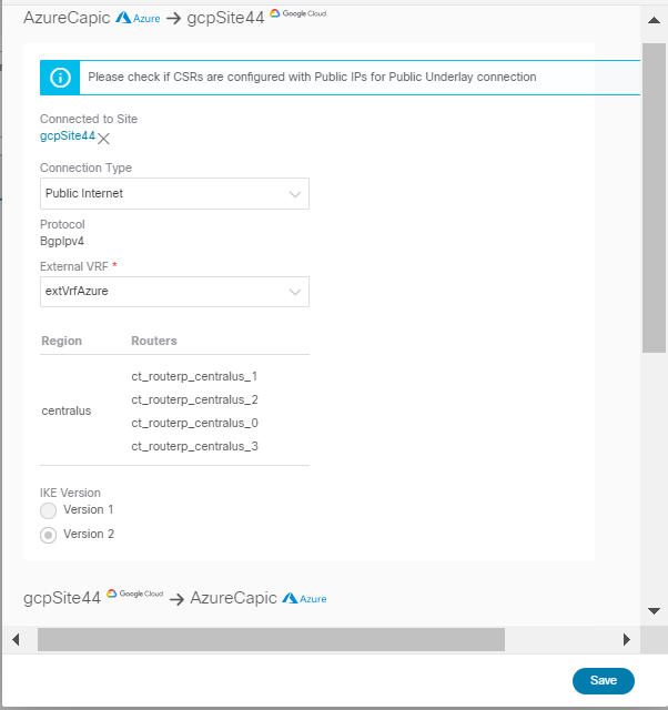
Under the Inter-Site Connectivity, Choose Add Site.

Step 5

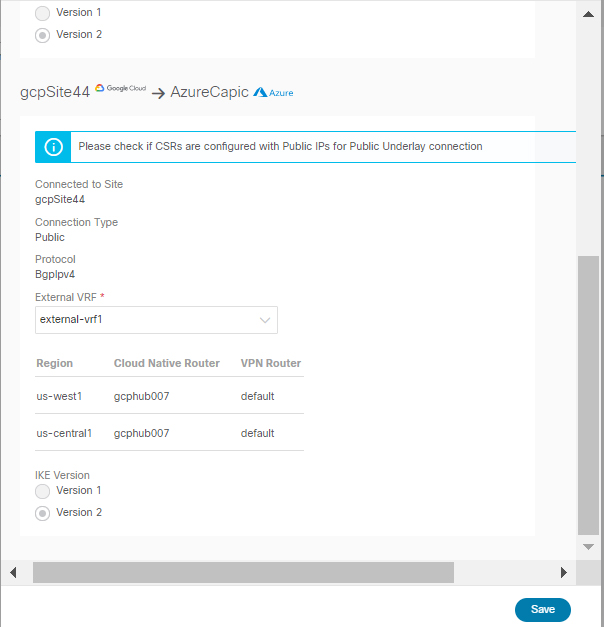
From the dialog window, under Connected to Site, select your cloud APIC site.

Under the Protocol you will see only see BGP-IPv4 as the Connectivity type. This is because you chose Google Cloud site and Google Cloud site only supports BGP-IPv4 connectivity.

Step 6

Choose the external VRF.

Step 7

From the External VRF dropdown, select the external VRF.

This is the external VRF you have configured in Creating External VRFs in Infra Tenant.

Step 8

Click Save to save the intersite connectivity configuration.


Deploying Infra Configuration

This section describes how to deploy the Infra configuration for the external connectivity from cloud sites.

Procedure


Step 1

In the top right of the main pane, choose Deploy > Deploy & Download External Device Config files.

The Deploy & Download External Device Config files option pushes the configuration to the Cloud APIC sites and enables the end-to-end interconnect from the cloud sites to the external devices.

In addition, this option downloads a zip file that contains configuration information that you will use to enable connectivity from external devices to Cloud site router deployed in your cloud sites. A followup screen appears that allows you to select all or some of the configuration files to download.

Step 2

In the confirmation window, click Yes.

The Deployment started, refer to left menu for individual site deployment status message will indicate that Infra configuration deployment began and you can verify each site's progress by the icon displayed next to the site's name in the left pane. After successful deployment, you can check the tunnels and BGP sessions created across cloud sites from Cloud APIC dashboard.


Creating an External EPG

This section describes how to create an external EPG in the Infra template using subnet selection. We will use this external EPG to represent the external networks, then configure and apply contracts between the external EPG and the cloud EPG to allow communication between the endpoints in your cloud site and the external networks.

Procedure


Step 1

In the Main menu, select Application Management > Schemas.

Step 2

Select the schema and the template that contains your external VRFs.

You can create similar configurations for all (AWS, Azure or Google Cloud ) Infra templates, but we recommend using different application profile names in the next step to avoid any possible confusion.

Step 3

Create an Application Profile in the template.

You will need to associate the external EPG you create with an application profile.

Step 4

Create and configure an External EPG.

  1. Select Create Object > External EPGs.

  2. In the external EPG's properties sidebar, select CLOUD for Site Type.

  3. From the Application Profile dropdown, select the profile you created in the previous step.

  4. From the Virtual Routing and Forwarding dropdown, select the external VRF you created.

Step 5

Configure the external EPG's site-local properties.

  1. In the left sidebar, select the template under a site to which it is assigned.

  2. In the template's site-local properties, select External-Site for Route Reachability.

  3. Click Add Selector.

  4. In the Add New Endpoint Selector dialog, provide the external subnet.

    This is an external subnet that requires connectivity to the cloud site, for which you configured route leaking in the previous section. For example, 172.16.8.0/24.

Step 6

Deploy the templates to create the external EPG in the cloud site.


Importing Google Cloud User Tenant

If you are importing an existing tenant follow the procedure below. If you wish to create a new tenant, refer to this section Creating Google Cloud User Tenant.

Procedure


Step 1

From the Nexus Dashboard's Service Catalog, open the Nexus Dashboard Orchestrator service.

You will be automatically logged in using the Nexus Dashboard user's credentials.

Step 2

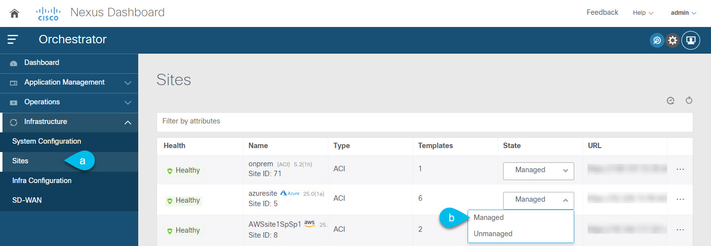
In the Nexus Dashboard Orchestrator GUI, manage the sites.

  1. From the left navigation menu, select Infrastructure > Sites.

  2. In the main pane, change the State from Unmanaged to Managed for each fabric that you want the Nexus Dashboard Orchestrator to manage.

Step 3

Import the existing cloud tenant.

  1. In the Sites page, click the actions (...) menu next to the site you enabled for management and select Import Tenants.

  2. In the Import Tenants dialog, select the tenant you want to import and click OK.

Step 4

Verify that the tenant's external connectivity infra configuration was imported successfully.

For external connectivity to be imported, it has to be configured on all the regions in which hub is instantiated.

  1. Navigate to Infrastructure > Site Connectivity page.

  2. Click Configure.

  3. In the General Settings page, select the External Devices tab.

    Verify that the external device is present

  4. In the General Settings page, select the IPSec Tunnel Subnet Pools tab.

    Verify that the external connectivity subnet pool is present.

  5. In the left sidebar, select the site from which you imported the tenant.

    In the site's settings, select the External Connectivity tab and confirm that the external network is present.

Note 

Do not deploy infra configuration from Nexus Dashboard at this time and proceed to the next section to import the external VRF.


Creating a Tenant

The following sections describe how to create a managed tenant or unmanaged tenant.

Setting Up the Google Cloud Project for a User Tenant

Perform the procedures in this section to set up the Google Cloud project for a user tenant, where that user tenant is either a managed or an unmanaged tenant.

Procedure


Step 1

Create a Google Cloud project for the user tenant, if necessary.

Each user tenant is mapped one-to-one to a Google Cloud project. If you do not have a Google Cloud project created yet for your user tenant, follow these procedures to create a Google Cloud project.

  1. Log into your Google account.

  2. Navigate to IAM & Admin > Manage resources.

  3. Using the Select organization drop-down list at the top of the page, choose the organization where you want to create a project.

  4. Click + CREATE PROJECT.

  5. In the New Project window that appears, enter a project name and select a billing account as applicable.

    A project name can contain only letters, numbers, single quotes, hyphens, spaces, or exclamation points, and must be between 4 and 30 characters.

  6. Enter the parent organization or folder in the Location field.

    That resource will be the hierarchical parent of the new project.

  7. Click CREATE.

Step 2

In Google Cloud, enable the appropriate service APIs in the service account associated with this user tenant.

  1. In the Google Cloud GUI, log into the Google Cloud project that is associated with this user tenant.

    The Dashboard for the project is displayed.
  2. In the search bar at the top of the Dashboard, search for APIs & Services, then click the result from that search to access the APIs & Services window.

  3. In the APIs & Services window, click the + ENABLE APIS AND SERVICES tab.

    The API Library window appears.

  4. In the Search for APIs & Services field, search for and enable the necessary services.

    For each of the services in the list below:

    1. Search for the API or service in the Search for APIs & Services field.

    2. Click on the search result to display the page for that API or service.

    3. Click the ENABLE button in that API or service page.

    Following are the APIs and services that you must search for and enable:

    • Compute Engine API

    • Cloud Deployment Manager V2 API

    • Cloud Pub/Sub API

    • Cloud Resource Manager API

    • Service Usage API

    • Cloud Logging API

    Each API or service takes several minutes to enable. You will have to navigate back to the APIs & Services window after you enable each API or service.

    Note that the following additional APIs and services should be enabled automatically when you enable all of the APIs and services listed above:

    • Identity and Access Management (IAM) API

    • IAM Service Account Credentials API

    • Cloud OS Login API

    • Cloud DNS API

    • Recommender API

    If they are not enabled automatically, enable them manually.

Step 3

Set the necessary permissions for this user tenant in Google Cloud.

  1. In the Google Cloud GUI, log into the Google Cloud project that is associated with this user tenant.

    The Dashboard for the project is displayed.
  2. In the left nav bar, click on IAM & Admin, then choose IAM.

    The IAM window appears with several service accounts displayed.

  3. Locate the appropriate service account.

  4. Set the permissions for this service account.

    1. Click the pencil icon on the row for this service account.

      The Edit Permissions window is displayed.

    2. Click + ADD ANOTHER ROLE, then choose Editor as the role.

      You are returned to the IAM window with the service accounts displayed.

    3. Click + ADD ANOTHER ROLE again, then add the remaining necessary roles for this service account.

      Following is the full list of roles that you must assign to this service account, including the Cloud Functions Service Agent that you added in the first step of this process:

      • Editor

      • Role Admin

      • Project IAM Admin

    4. After you have added all the necessary roles, click SAVE.

      You are returned to the IAM window with the service accounts displayed and the necessary roles assigned to this service account.


Generating and Downloading Private Key Information from Google Cloud for an Unmanaged Tenant

If you are creating an unmanaged tenant, you must first generate and download the necessary private key information from Google Cloud.


Note

You do not have to follow the steps in this procedure if you are creating a managed tenant.


Procedure


Step 1

In Google Cloud, select the Google Cloud project that will be associated with this unmanaged tenant, if you have not selected it already .

Step 2

In the left nav bar, click on IAM & Admin, then choose Service Accounts.

The service accounts for this Google Cloud project are displayed.

Step 3

Select an existing service account or click + CREATE SERVICE ACCOUNT to create a new one.

Information on this service account is displayed, with the Details tab selected by default.

Step 4

Click the KEYS tab.

Step 5

Click ADD KEY > Create New Key.

A window appears, providing an option to create a private key for this service account.

Step 6

Leave the JSON key type selected, then click Create.

A window appears, saying that the private key has been saved to your computer.

Step 7

Locate the JSON file that was downloaded to your computer and move it to a secure location on your computer.

This JSON file will contain the key information that you need to fill in the fields for the unmanaged tenant.


Creating Google Cloud User Tenant

Before you begin

You must make certain configurations in Google Cloud before creating a Google Cloud user tenant in the Nexus Dashboard Orchestrator:

Procedure


Step 1

Log in to your Nexus Dashboard Orchestrator.

Step 2

In the left navigation menu, choose "Tenants".

Step 3

Choose "Add Tenant".

Step 4

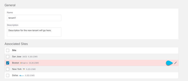
Under General, provide a tenant name and an optional description.

The tenant name must be in the following format:

[a-z]([-a-z0-9]*[a-z0-9])?

This means that the first character must be a lowercase letter, and all the following characters can be hyphens, lowercase letters, or digits, except the last character, which cannot be a hyphen.

Step 5

From the Associated Sites area, choose the Google Cloud site where you want to create the tenant.

Step 6

After selecting your Google Cloud site, click on the edit icon to specify your account information.

Step 7

Fill in all the mandatory information.

Step 8

Choose Save after filling in the configuration for the Google Cloud.


What to do next

If you are creating a managed tenant, you must now set the necessary permissions in Google Cloud for the managed tenant. Go to Setting the Necessary Permissions in Google Cloud for a Managed Tenant for those procedures.

Setting the Necessary Permissions in Google Cloud for a Managed Tenant

If you are creating a managed tenant, you must now set the necessary permissions in Google Cloud.


Note

You do not have to follow the steps in this procedure if you are creating an unmanaged tenant.


Procedure


Step 1

In the Google Cloud GUI, log into the Google Cloud project that is associated with this managed tenant.

The Dashboard for the project is displayed.

Step 2

In the left nav bar, click on IAM & Admin, then choose IAM.

The IAM window appears with several service accounts displayed.

Step 3

Locate the service account that was created in the project that is associated with the infra account.

Step 4

Copy the service account name.

Step 5

Add this service account name as an IAM user in the user tenant project.

Step 6

Set the permissions for this service account.

  1. Click the pencil icon on the row for this service account.

    The Edit Permissions window is displayed.

  2. Click + ADD ANOTHER ROLE, then choose Cloud Functions Service Agent as the role.

    You are returned to the IAM window with the service accounts displayed.

  3. Click + ADD ANOTHER ROLE again, then add the remaining necessary roles for this service account.

    Following is the full list of roles that you must assign to this service account, including the Cloud Functions Service Agent that you added in the first step of this process:

    • Cloud Functions Service Agent

    • Compute Instance Admin (v1)

    • Compute Network Admin

    • Compute Security Admin

    • Logging Admin

    • Pub/Sub Admin

    • Storage Admin

  4. After you have added all the necessary roles, click SAVE.

    You are returned to the IAM window with the service accounts displayed and the necessary roles assigned to this service account.


Creating Cloud EPGs

We recommend creating cloud objects in a separate template and schema from the Infra tenant configuration (such as external VRFs) you have already done.

Use the following procedure to create a new schema for the Cloud APIC site. For this use-case example, we will configure a single schema and one template.

You are in the Nexus Dashboard Orchestrator for this entire procedure.

Procedure


Step 1

In the Main menu, click Schemas.

Step 2

On the Schema screen, click the Add Schema button.

Step 3

On the Untitled Schema screen, replace the text Untitled Schema at the top of the page with a name for the schema that you intend to create (for example, schema-1).

Step 4

Create a template.

If your Google cloud site has BGP-EVPN intersite connectivity, choose ACI Multi-Cloud template type; if the site has BGP-IPv4 connectivity, choose Cloud Local.

  1. In the left pane, mouse over Template 1 and click the notepad icon. Then change the template's name, for example in Google Cloud case template1-gcp.

  2. In the middle pane, click the area To build your schema please click here to select a tenant.

  3. In the right pane, access the Select A Tenant dialog box and choose the tenant you want. This is the tenant you imported Importing Google Cloud User Tenant or created in Creating Google Cloud User Tenant.

Step 5

After choosing the tenant, create an Application Profile in the template.

You will need to associate the cloud EPG you create with an application profile.

Step 6

Create and configure a Cloud EPG.

  1. Select Create Object > Cloud EPGs.

  2. From the Application Profile dropdown, select the profile you created in the previous step.

  3. From the Virtual Routing and Forwarding dropdown, select the cloud VRF you created.

  4. In the right-hand properties sidebar, select the cloud VRF you created for this EPG.

Step 7

Assign the template you just created to the Google Cloud site.

Step 8

Configure the cloud EPG's site-local properties.

  1. In the left sidebar, select the template under a site to which it is assigned.

  2. In the template's site-local properties, select Cloud Site for Route Reachability.


Creating Schema, Template and VRFs for your Google Cloud Site

Procedure


Step 1

In the Main menu, click Schemas.

Step 2

On the Schema screen, click the Add Schema button.

Step 3

On the Untitled Schema screen, replace the text Untitled Schema at the top of the page with a name for the schema that you intend to create (for example, schema-1).

Step 4

Configure the first template.

If your Google cloud site has BGP-EVPN intersite connectivity, choose ACI Multi-Cloud template type; if the site has BGP-IPv4 connectivity, choose Cloud Local.

Step 5

In the left pane, mouse over Template 1 and click the notepad icon. Then change the template's name (for example, template1-gcp).

Step 6

Navigate to your cloud template.

Step 7

Choose Add VRF under VRFs, then enter the display name and description for the VRF.

Step 8

Click on the VRF that you just created.

The Template Properties and Site Local Properties are displayed on the right side of your screen.

Step 9

Under Site Level Properties, choose Add Region.

In the pop-up, select the region that you want.

Step 10

After selecting the region, choose Add CIDR.

Enter the CIDR information for the VRF.

  • Choose Primary if you are adding a primary CIDR.

  • Choose Secondary if you are adding a secondary CIDR.

Step 11

Enter the Subnet and Subnet Group Label.

When creating a subnet, you will use the Subnet Group Label to assign a unique label to a specific subnet group. For more details on configuring CIDR, subnets, and subnet group labels, see "Understanding VPCs and Subnets Under Google Cloud and Cloud Context Profiles Under Cloud APIC" in the Cisco Cloud APIC for Google Cloud User Guide.

Step 12

Choose Save.


Configuring an Application Profile and EPG

Procedure


Step 1

In the middle pane click + Application Profile.

Step 2

In the right pane, enter the Application Profile name in the Display Name field (for example, app1).

Step 3

n the middle pane, click + Add EPG.

Step 4

In the right pane, enter an EPG name in the Display Name field.

Step 5

In the Cloud Properties area, you can see the VRF you just created in the previous section (for example, cloud-vrf).


Adding Cloud Endpoint Selector

On the Cloud APIC, a cloud EPG is a collection of endpoints that share the same security policy. Cloud EPGs can have endpoints in one or more subnets and are tied to a CIDR. You define the endpoints for a cloud EPG using an object called endpoint selector. The endpoint selector is essentially a set of rules run against the cloud instances assigned to either AWS, Azure or Google Cloud managed by the Cloud APIC. Any endpoint selector rules that match endpoint instances will assign that endpoint to the Cloud EPG. Unlike the traditional on-premises ACI fabrics where endpoints can only belong to a single EPG at any one time, it is possible to configure endpoint selectors to match multiple Cloud EPGs. This in turn would cause the same instance to belong to multiple Cloud EPGs. However, we recommend configuring endpoint selectors in such a way that each endpoint matches only a single EPG. The section below will walk you through the process of Adding End point Selector.

Procedure


Step 1

In the Nexus Dashboard Orchestrator, select the EPG you create in the previous section.

Step 2

In the right pane, in the Site Local Properties area, click + Selector under the Selectors heading to configure the endpoint selector.

If you plan to stretch this EPG, you can also choose to add the endpoint selector at the template level instead.

Step 3

In the Add New End Point Selector form, enter a name in the End Point Selector Name field, based on the classification that you use for this endpoint selector.

For example, for an endpoint selector with the IP Subnet classification, you might use a name such as IP-Subnet-EPSelector.

Step 4

Click + Expression, then use the three fields to configure the endpoint selector based on how you want to classify the endpoints in the cloud:

The Type field determines the expression that you want to use for the endpoint selector:

  • Choose IP Address if you want to use an individual IP address or a subnet for the endpoint selector.

  • Choose Region if you want to use the cloud region for the endpoint selector, then choose the specific region that you want use.

    When you select Region for the endpoint selector, every instance within the tenant that is brought up in that region will be assigned to this cloud EPG.

  • Choose Custom tags or labels if you want to create a custom tag or label for the endpoint selector. Start typing to enter the custom tag or label, then click Create on the new field to create a new custom tab or label.

The Operator field determines the relation between the type and its value:

  • Equals: Used when you have a single value in the Value field.

  • Not Equals: Used when you have a single value in the Value field.

  • In: Used when you have multiple comma-separated values in the Value field.

  • Not In: Used when you have multiple comma-separated values in the Value field.

  • Has Key: Used if the expression contains only a key.

  • Does Not Have Key: Used if the expression contains only a key.

The Value field determines the collection of endpoints that you want to use for the endpoint selector, based on the choices that you made for the two previous fields. This can be a single IP address, a subnet, AWS region or zone, or a custom tag value.

For this use case, you will be assigning endpoints based on IP subnets, so you will configure the endpoint selector using the following example values:

  • Type: IP Address

  • Operator: Equals

  • Value: 3.3.1.0/24

Step 5

Click the checkmark next to the new endpoint selector.

Step 6

Click Save in the Add New End Point Selector form.


Applying Contract Between External EPG and Cloud EPG

This section describes how to apply a contract to allow communication between the endpoints in your cloud site and the external networks. One thing to keep in mind regarding Google Cloud contracts is that the contracts should be deployed bi-directionally for bi-directional traffic.

Before you begin

Procedure


Step 1

In the Main menu, select Application Management > Schemas.

Step 2

Create a contract and assign it to the cloud EPG.

  1. Select the schema and the template that contains your existing cloud EPG.

  2. Create the contract you will use for this use case.

    If you already have an existing contract you want to apply for communication between the external network and the Cloud EPG, you can skip this step.

    Otherwise, create a contract and the required filters as you typically would for any inter-EPG communication in Cisco ACI fabrics.

  3. Assign the contract to the cloud EPG.

    You can decide which of the two EPGs (cloud EPG and external EPG) will be the provider and which will be the consumer based on your specific use case.

Step 3

Assign the contract to the External EPG.

  1. Select the schema and the template where you created your external EPG.

  2. Assign the contract to the external EPG.

    If you configured your cloud EPG to be the provider, choose consumer for the external EPG; otherwise, if the cloud EPG is the consumer, choose provider.

    Note 

    Contract scope must be set to "global", so the contract can used between external EPG and cloud EPG.

Step 4

Deploy the templates.


Configuring Route Leaking Between Cloud VRF and External VRF

This use case focuses on route leaking between a google cloud VRF (in a user tenant) and an external VRF (in Infra tenant) in order to establish traffic flow between your google cloud site and another cloud or on-premises site.If you want to configure route leaking between two cloud VRFs (for example, to enable traffic flow within the same Google Cloud site), see Configuring Route Leaking between Two Cloud VRFs.

Before you begin

You must have one or more cloud VRFs already configured in your cloud site. You will configure route leaking from the external VRF to an existing cloud VRF.

Procedure


Step 1

In the Main menu, select Application Management > Schemas.

Step 2

Configure route leaking from external VRF to a cloud VRF.

The following steps show how to configure the following route leaking:

  1. Open the schema where you created the Infra tenant template containing the external VRF.

  2. In the left sidebar under SITES, select that specific template associated to the cloud site.

  3. In the site-local properties, select the external VRF defined in the template.

    This is the VRF you created and assigned to one or more external devices .

  4. In the VRF's right-hand properties sidebar, click +Add Leak Route.

    The Add Leak Routes dialog will open.

  5. In the Add Leak Routes dialog's settings area, click Select a VRF and choose a cloud VRF.

    The goal of this step is to leak routes from the external VRF to the cloud VRFs, so select the cloud VRF to which you want to leak routes from the external VRF whose properties you are configuring.

  6. In the Add Leak Routes dialog, choose Leak All routes, or limit it to a specific Subnet IP.

    After selecting Leak All, the subnet IP will be populated with 0.0.0.0/0 to leak all routes. If you choose to limit which routes to leak, click +Add Subnet IP and provide the subnet from your cloud VRF which you want to be reachable from the external network, for example 81.0.1.0/24. Click the checkmark icon to save the subnet information.

  7. Click Save to save the route leak configuration.

  8. Select the template and click Deploy to deploy the configuration.

Step 3

Configure route leaking from a cloud VRF to the external VRF.

The following steps show how to configure the route leaking in the other direction:

  1. Open the schema which contains the template that defines your cloud VRF.

  2. In the left sidebar under SITES, select the specific cloud site.

  3. In the site-local properties, select the cloud VRF.

  4. In the VRF's right-hand properties sidebar, click +Add Leak Route.

    The Add Leak Routes dialog will open.

  5. In the Add Leak Routes dialog's settings area, click Select a VRF and choose the external VRF.

    The goal of this step is to leak routes from the cloud VRF to the external VRF, so select the external VRF that you created.

  6. In the Add Leak Routes dialog, choose whether you want to Leak All routes or limit it to a specific Subnet IP.

    If you select Leak All, the subnet IP will be populated with 0.0.0.0/0 to leak all routes.

    If you choose to limit which routes to leak, click +Add Subnet IP and provide the subnet from your cloud VRF which you want to be reachable from the external network, for example 81.0.1.0/24. Click the checkmark icon to save the subnet information.

  7. Click Save to save the route leak configuration.

  8. Select the template and click Deploy to deploy the configuration.