Installation, Maintenance, and Upgrade

Power the Unit via the AC Power Supply

Safety Warnings

Take note of the following warnings:


Warning


Ensure the unit's power source(s) have been turned OFF before servicing.


To power the unit:

Procedure


Step 1

Connect the AC plug to the AC appliance coupler.

Step 2

Plug the power cord into a suitable power outlet.

Step 3

Secure the power cord through the retainer clip.

Warning


The AC plug must be connected to a properly grounded AC outlet.


Power the Unit via DC Power Cable

Safety Warnings

Take note of the following warning:


Warning


Each input should be protected by a 1.5 to 2.0 A externally-mounted fast-acting fuse or equivalent. There should be one fuse per power feed. Disconnect all power sources before servicing. Removing fuses can be used as a disconnect method. Fuses must be installed on the live wire(s) and not on the grounded wire(s).


To power the unit via the DC power cable:

Before you begin

  • Make sure that the chassis ground is connected on the chassis before you begin installing the DC power supply. See Ground the Chassis for the procedure.

Procedure


Step 1

Establish the proper connections between the cable end and the power sources.

Step 2

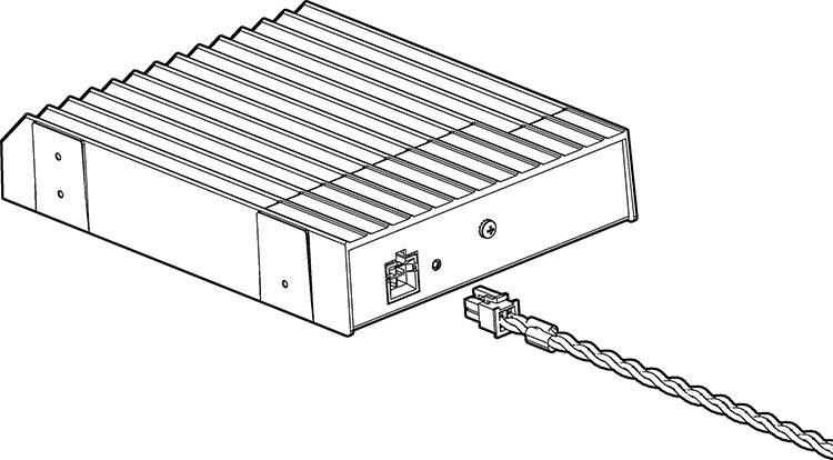
Connect the DC connector to the back of the Module.

Figure 1. Connect the DC Connector

Power the Unit via DC Terminal Block Adapter

Safety Warnings

Take note of the following warning:


Warning


Each input should be protected by a 1.5 to 2.0 A externally-mounted fast-acting fuse or equivalent. There should be one fuse per power feed. Disconnect all power sources before servicing. Removing fuses can be used as a disconnect method. Fuses must be installed on the live wire(s) and not on the grounded wire(s).


To power the unit via the terminal block adapter:

Before you begin

  • Make sure that the chassis ground is connected on the chassis before you begin installing the DC power supply. See Ground the Chassis for the procedure.

Procedure


Step 1

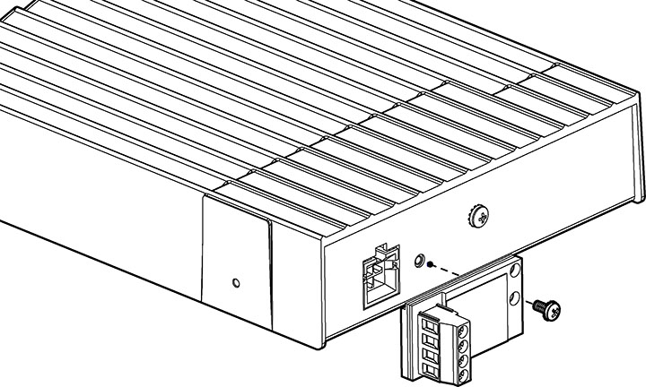
Fasten the Terminal Block Adapter to the back of the Module.

Figure 2. Fasten the Terminal Block Adapter

Step 2

Establish the proper connections between the wires and the power sources.

Step 3

Connect wires to the terminal block connector of the adapter.

Note


Applicable wire range: 0.34 to 4 mm2 (22 to 12AWG)


Connect to the Network

Establish the Ethernet connections to the unit by plugging the appropriate media types to the proper ports of the unit (see Front Panel).


Note


For more information, refer to the User Material.


Warning


The intra-building ports of the equipment or subassembly is suitable for connection to intra-building or unexposed wiring or cabling only. The intra-building ports of the equipment MUST NOT be metallically connected to interfaces that connect to the OSP or its wiring.