SR-MPLS and SRv6

This section describes the SR-MPLS and SRv6 policy features that Crosswork supports. For a list of known limitations and important notes, see the Cisco Crosswork Optimization Engine Release Notes .

View SR-MPLS and SRv6 Policies on the Topology Map

To get to the Traffic Engineering topology map, choose Traffic Engineering > Traffic Engineering.

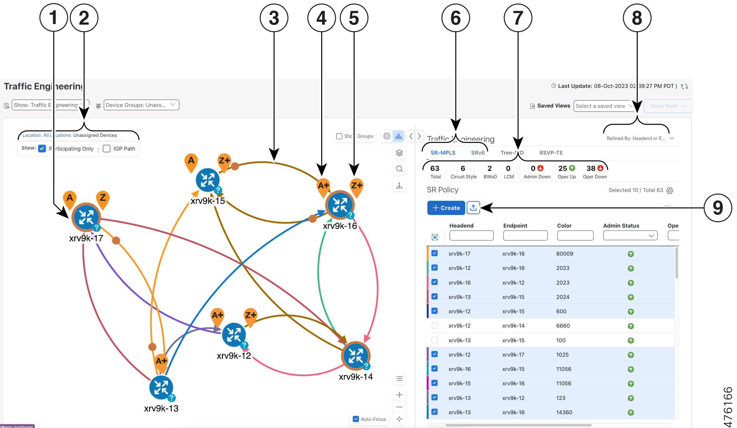
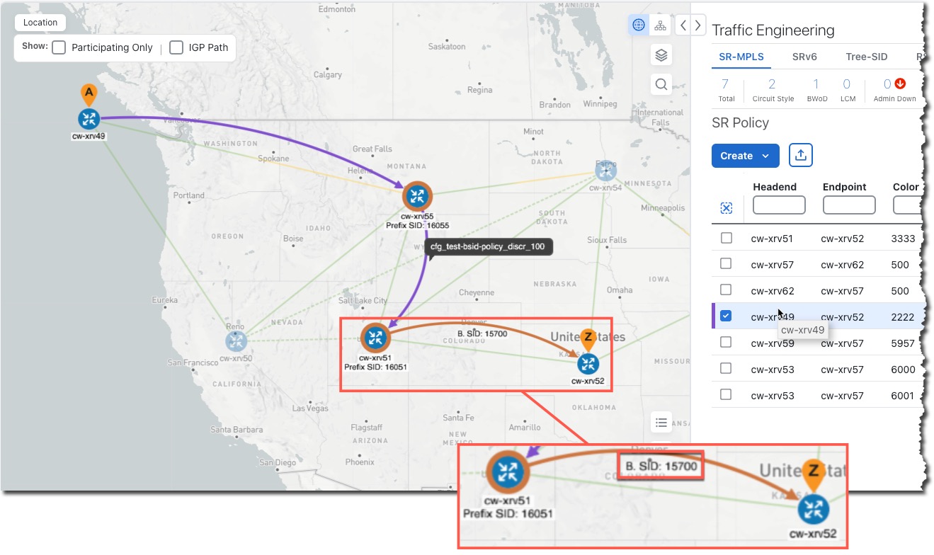
From the Traffic Engineering table, click the checkbox of each SR-MPLS or SRv6 policy you want to view on the map. You can select up to 10 policies that will appear as separate colored links.

Figure 1. Traffic Engineering UI : SR-MPLS and SRv6 Policies
Callout No. Description

1

A device with an orange (Node SID) outline indicates there is a node SID associated with that device or a device in the cluster.

2

Click the appropriate check box to enable the following options:

  • Show IGP Path—Displays the IGP path for the selected SR-TE policy.

  • Show Participating Only—Displays only links that belong to selected SR-TE policy. All other links and devices disappear.

3

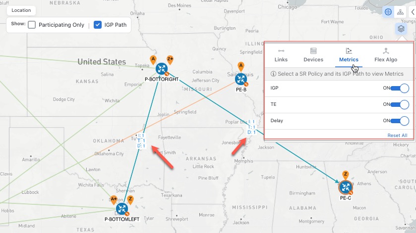
When SR-TE policies are selected in the SR-MPLS or SRv6 tables, they show as colored directional lines on the map indicating source and destination.

An adjacency segment ID (SID) is shown as an orange circle on a link along the path (Adjacency SID).

4

SR-MPLS and SRv6 Policy Origin and Destination: If both A and Z are displayed in a device cluster, at least one node in the cluster is a source and another is a destination. The A+ denotes that there is more than one SR-TE policy that originates from a node. The Z+ denotes that the node is a destination for more than one SR policy.

5

The content of this window depends on what has been selected or filtered. In this example, the SR-MPLS tab is selected and the SR Policy table is displayed.

6

Click on either the SR-MPLS or SRv6 tabs to view the respective list of SR-TE policies.

7

The Mini Dashboard provides a summary of the operational SR-MPLS or SRv6 policy status. If filters are applied, the Mini Dashboard is updated to reflect what is displayed in the SR Policy and SRv6 Policy tables. In addition to the policy status, the SR-MPLS Mini Dashboard table displays the number of PCC and PCE initiated tunnels that are currently listed in the SR Policy table.

8

This option allows you to choose how the group filter (when in use) should be applied on the table data. For example, if Headend only was selected, then it would only display policies where the headend device of the policy is in the selected group. This filter allows you to see specific configurations and is useful when you have a large network.

Filter options:

  • Headend or Endpoint—Show policies with either the headend or endpoint device in the selected group.

  • Headend and Endpoint—Show policies if both the headend and endpoint are in the group.

  • Headend only—Show policies if the headend device of the policy is in the selected group.

  • Endpoint only—Show policies if endpoint device of the policy is in the selected group.

9

Exports all data into a CSV file. You cannot export selected or filtered data.

View SR-MPLS and SRv6 Policy Details

View SR-MPLS or SRv6 TE policy level details as well segment lists and any path computation constraints configured on a per-candidate path basis.

Procedure


Step 1

From the Actions column, click More icon > View Details for one of the SR-MPLS or SRv6 policies.

Step 2

View SR-MPLS or SRv6 policy details. From the browser, you can copy the URL and share with others.

Note


The Delay value is calculated for all policies every 10 minutes. Hover your mouse over the "i" icon (next to the Delay value) to view the last time the value was updated.

Figure 2. SR Policy Details - Headend, Endpoint, and Summary

Headend, Endpoint, and Summary
Figure 3. SR Policy Details - Candidate Path

SR Policy Details - Candidate Path

Visualize IGP Path and Metrics

View the physical path and metrics between the endpoints of the selected SR-MPLS policies.

Procedure


Step 1

From the SR Policy table, check the check box next to the SR-TE (SR-MPLS and SRv6) policies you are interested in.

Step 2

Check the Show IGP Path check box. The IGP paths for the selected SR-MPLS policies are displayed, with straight lines, instead of the segment hops. In a dual stack topology, the Participating Only checkbox must also be checked to view metrics on participating links.

Step 3

Click Display Preferences icon > Metrics tab.

Step 4

Toggle applicable metrics to ON.

Note


You must check the Show IGP Path check box in order to view metrics.


View Physical Path and Metrics Example

Find Multiple Candidate Paths (MCPs)

Visualizing MCPs gives you insight into which paths might be a better alternative to the currently active one. If you determine to do so, you can then manually configure the device and change which path becomes active.

Important Notes

  • Only PCC-initialized SR-TE policies with MCPs are supported.

  • Crosswork Optimization Engine does not distinguish dynamic paths versus explicit paths. The Policy Type field value displays as 'Unknown'.

  • You can view active explicit paths, but not inactive candidate explicit paths in the UI.

Before you begin

A policy must be configured with MCPs on devices before visualizing them on the Traffic Engineering topology map. This configuration can be done manually or within Crosswork Network Controller.

Procedure


Step 1

From the main menu, choose Traffic Engineering > Traffic Engineering > SR-MPLS or SRv6 tab.

Step 2

Navigate to the active SR-TE policy that has MCPs configured and view it on the topology map.

  1. Check the check box next to the SR-TE policy that has MCPs configured.

  2. View the SR-TE policy that is highlighted on the topology map.

In this example, you see that the active path is going from xrv9k-12 > xrv9k-14 > xrv9k-16.
Active MCP

Step 3

View the list of candidate paths.

  1. From the SR-TE Policy table Actions column, click More icon > View Details. A list of candidate paths appear along with policy details in the SR Policy Details window. The green A in the state column indicates the active path.
    MCP Details

Step 4

You can expand individual paths or click Expand All to view details of each path.

Step 5

Visualize the candidate path on the topology map.

  1. Check the check box next to any candidate path.

    Note


    You will not be able to select or view explicit candidate paths.

  2. From the Candidate Path area, hover your mouse over the candidate path name. The candidate path is highlighted on the topology map.

    In this example, you see that the alternate path goes directly from xrv9k-12 > xrv-16.
    Candidate Path on Map

Visualize Underlying Paths Associated with a Defined Binding-Segment ID (B-SID) Label

Cisco Crosswork allows you to visualize the underlying path of a B-SID hop that you have manually configured on a device or configured using Crosswork Network Controller. In this example, we have assigned 15700 as a B-SID label on an SR-MPLS policy hop.

To view the B-SID underlying path for an SR-MPLS or SRv6 policy, do the following:

Procedure


Step 1

From the main menu, choose Traffic Engineering > Traffic Engineering > SR-MPLS .

Step 2

From the SR Policy table, check the check box next to the policy that has a hop assigned with a B-SID label. Hover your mouse over any part of the SR-MPLS row to see the B-SID name. The B-SID path is highlighted in orange on the topology map.

In this example, you see that the B-SID path is going from cw-xrv51 to cw-xrv52.

B-SID Label

Step 3

From the Actions column, click More icon > View Details.

Step 4

From the SR Policy Details window, expand the active path name to view more information. In this example, the underlying path actually goes from cw-xrv51 > cw-xrv54 > cw-xrv53 > cw-xrv52.

B-SID Label

Visualize Native SR Paths

Visualizing the native path will help you in OAM (Operations, Administration and Maintenance) activities to monitor label-switched paths (LSPs) and quickly isolate forwarding problems to assist with fault detection and troubleshooting in the network. Since this feature uses multipaths, all ECMP paths are shown between the source and destination. You can visualize only native SR IGP paths.

Before you begin

Confirm that device requirements are met. See Visualize Native Path Device Prerequisites.

To create a path query, do the following:

Procedure


Step 1

From the main menu, choose Traffic Engineering > Path Query. The Path Query dashboard appears.

Step 2

On the Path Query dashboard, click New Query.

Step 3

Enter the device information in the required fields to find available Native SR IGP Paths.

Step 4

Click Get Paths. The Running Query ID pop-up appears.

Note


Path queries may take a moment to complete. When the Running Query ID pop-up appears, you can also select View Past Queries to return to the Path Query Dashboard. If you already had path queries in the list, you can view existing details as the new query continues to run in the background, which is indicated by the blue Running icon in the Query State column. When the new query state turn green, completed, it can be viewed.

Step 5

Click View Result when it becomes available on the Running Query ID pop-up. The Path Details panel appears with corresponding available paths details while the defined topology map appears with the available Native SR IGP Paths on the left.

Example:

In the below example, you can view the available paths : Path 0

Figure 4. Path Details

Step 6

From the main menu, choose Traffic Engineering > Path Query. to return to the Path Query dashboard.

Step 7

From the Actions column, click View Details.

If you have not provided the longitude and latitude information for your devices, the path is visualized in the logical view.

Step 8

From the available paths, click Path 0 to expand and view the active path.

Example:

Figure 5. Path Details

Visualize Native Path Device Prerequisites

Confirm the following device software and configurations are met prior to visualizing native paths.

  1. Devices should be running Cisco IOS XR 7.3.2 or higher. Run show version command to verify it.

  2. Devices should have GRPC enabled.

    1. Run show grpc to confirm GRPC configuration. You should see something similar to this:

      tpa
      vrf default
      address-family ipv4
      default-route mgmt
      !
      address-family ipv6
      default-route mgmt
      !
      !
      !
      
      or
      
      linux networking
      vrf default
      address-family ipv4
      default-route software-forwarding
      !
      address-family ipv6
      default-route software-forwarding
      !
      !
      ! 

    Note


    • address-family is only required in an IPv4 topology.

    • To enable GRPC with a secure connection, you must upload security certificates to connect to the device.


  3. Devices should have GNMI capability enabled and configured.

    1. From Device Management > Network Devices, click icon for the device you are interested.

    2. Confirm that GNMI is listed under Connectivy Details.


    Note


    Based on the type of devices, the following device encoding type are available:

    • JSON

    • BYTES

    • PROTO

    • ASCII

    • JSON IETF


  4. Devices should have the CDG router static address. Static route should be added from the device to the southbound CDG IP address. For example:

    RP/0/RP0/CPU0:xrvr-7.3.2#config
    
    RP/0/RP0/CPU0:xrvr-7.3.2(config)#router static
    
    RP/0/RP0/CPU0:xrvr-7.3.2(config-static)#address-family ipv4 unicast <CDG Southbound interface IP: eg. 172.24.97.110> <Device Gateway eg: 172.29.105.1>
    
    RP/0/RP0/CPU0:xrvr-7.3.2(config-static)#commit


Configure TE Link Affinities

If you have any affinities you wish to account for when provisioning an SR policy, Tree-SID, or RSVP-TE tunnel, then you can optionally define affinity mapping on the Cisco Crosswork UI for consistency with affinity names in device configurations. Cisco Crosswork will only send bit information to SR-PCE during provisioning. If an affinity mapping is not defined in the UI, then the affinity name is displayed as "UNKNOWN". If you want to configure affinity mappings in Cisco Crosswork for visualization purposes, you should collect affinities on the device, then define affinity mapping in the Cisco Crosswork UI with the same name and bits that are used on the device.

The affinity configuration on interfaces simply turns on some bits. It is a 32-bit value, with each bit position (0–31) representing a link attribute. Affinity mappings can be colors representing a certain type of service profile (for example: low delay, high bandwidth, and so on). This makes it easier to refer to link attributes.

See SR, Tree-SID, or RSVP-TE configuration documentation for your specific device to view descriptions and supported configuration commands (for example: Segment Routing Configuration Guide for Cisco ASR 9000 Series Router)

The following example shows the affinity configuration (affinity-map) on a device:

RP/0/RP0/CPU0:c12#sh running-config segment-routing traffic-eng affinity-map
Wed Jul 27 12:14:50.027 PDT
segment-routing
 traffic-eng
  affinity-map
   name red bit-position 1
   name blue bit-position 5
   name green bit-position 4
  !
 !
! 

Procedure


Step 1

From the main menu, choose Administration > Settings > System Settings tab > Traffic Engineering > Affinity > TE Link Affinities. You can also define affinities while creating an SR-TE policy, Tree-SID, or RSVP-TE tunnel by clicking Manage Mapping.

Step 2

To add a new affinity mapping, click + Create.

Step 3

Enter the name and the bit it will be assigned. For example (using the above configuration):

Example:

TE Affinity Example

Step 4

Click Save to save the mapping.

Note


You should remove the TE tunnel before removing the affinity to avoid orphan TE tunnels. If you have removed an affinity associated to a TE tunnel, the affinity is shown as "UNKNOWN" in the SR Policy / RSVP-TE Tunnel Details window.


Create Explicit SR-MPLS Policies

This task creates SR-MPLS policies using an explicit (fixed) path consisting of a list of prefix or adjacency Segment IDs (SID list), each representing a node or link along on the path.


Tip


If you plan to use affinities, collect affinity information from your devices, and then map them in Cisco Crosswork before creating an explicit SR-MPLS policy. For more information, see Configure TE Link Affinities.

Procedure


Step 1

From the main menu, choose Traffic Engineering > Traffic Engineering > SR-MPLS tab.

Step 2

From the SR Policies table, click + Create.

Step 3

Enter or select the required SR-MPLS policy values. Hover the mouse pointer over the Field Help icon to view a description of the field.

Tip


If you have set up device groups, you can select the device group from the Device Groups drop-down list. Then navigate and zoom in on the topology map to click the device for headend or endpoint selection.

Step 4

Under Policy Path, click Explicit Path and enter a path name.

Step 5

Add segments that will be part of the SR-MPLS policy path.

Step 6

Click Preview and confirm that the policy you created matched your intent.

Step 7

If you want to commit the policy path, click Provision to activate the policy on the network or exit to abort the configuration process.

Step 8

Validate the SR-MPLS policy creation:

  1. Confirm that the new SR-MPLS policy appears in the SR Policy table. You can also click the check box next to the policy to see it highlighted in the map.

    Note

     
    The newly provisioned SR-TE policy may take some time, depending on the network size and performance, to appear in the SR Policy table. The SR Policy table is refreshed every 30 seconds.
  2. View and confirm the new SR-MPLS policy details. From the SR Policy table, click the More icon and select View.

Note


On a setup with high node, policy, or interface counts, a timeout may occur during policy deployment. To configure timeout options, see Configure TE Timeout Settings.


Create Dynamic SR-MPLS Policies Based on Optimization Intent

This task creates an SR-MPLS policy with a dynamic path. SR-PCE computes a path for the policy based on metrics and path constraints (affinities or disjointness) defined by the user. A user can select from three available metrics to minimize in path computation: IGP, TE, or latency. The SR-PCE will automatically re-optimize the path as necessary based on topology changes. In the event of a link or interface failing, the network will find an alternate path that meets all the criteria specified in the policy and raise an alarm. The alarm is also raised in case no path is found, the packets are then dropped.


Tip


For visualization purposes, you can optionally collect affinity information from your devices and then map them in Cisco Crosswork before creating a dynamic SR-MPLS policy. For more information, see Configure TE Link Affinities or Configure Flexible Algorithm Affinities.

Procedure


Step 1

From the main menu, choose Traffic Engineering > Traffic Engineering > SR-MPLS tab.

Step 2

From the SR Policy table, click + Create.

Step 3

Under Policy Details, enter or select the required SR-MPLS policy values. Hover the mouse pointer over Field Help icon to view a description of each field.

Tip


If you have set up device groups, you can select the device group from the Device Groups drop-down menu. Then navigate and zoom in on the topology map to click the device for headend or endpoint selection.

Step 4

Under Policy Path, click Dynamic Path and enter a path name.

Step 5

Under Optimization Objective, select the metric you want to minimize.

Step 6

Define any applicable constraints and disjointness.

Note

 
  • Affinity constraints and disjointness cannot be configured on the same SR-MPLS policy. Also, there cannot be more than two SR-MPLS policies in the same disjoint group or subgroup. The configuration will not be allowed during Preview.

  • If there are existing SR-MPLS policies belonging to a disjoint group that you define here, all SR-MPLS policies that belong to that same disjoint group are shown during Preview.

Step 7

Under Segments, select whether or not protected segments should be used when available.

Step 8

If applicable, enter a SID contraint in the SID Algorithm field. Cisco Crosswork will try to find a path with this SID. If a path with the SID constraint cannot be found, the provisioned policy will remain operationally down until the conditions are met.

Note

 
  • Flexible Algorithm: The values correspond to the Flexible Algorithm that are defined on the device and the 128-255 range is enforced by Cisco IOS XR.

  • Algorithm 0: This is a Shortest Path First (SPF) algorithm based on link metric. This shortest path algorithm is computed by the Interior gateway protocol (IGP).

  • Algorithm 1: This is a Strict Shortest Path First (SSPF) algorithm based on link metric. The algorithm 1 is identical to algorithm 0 but requires that all nodes along the path honor the SPF routing decision. Local policy does not alter the forwarding decision. For example, a packet is not forwarded through locally engineered path.

Step 9

Click Preview. The path is highlighted on the map.

Step 10

If you want to commit the policy path, click Provision.

Step 11

Validate the SR-MPLS policy creation:

  1. Confirm that the new SR-MPLS policy appears in the SR Policy table. You can also click the check box next to the policy to see it highlighted in the map.

    Note

     
    The newly provisioned SR-MPLS policy may take some time, depending on the network size and performance, to appear in the SR Policy table. The SR Policy table is refreshed every 30 seconds.
  2. View and confirm the new SR-MPLS policy details. From the SR Policy table, click More icon and select View.

Note


On a scaled setup with high node, policy, or interface counts, a timeout may occur during policy deployment. To configure timeout options, see Configure TE Timeout Settings.


Modify SR-MPLS Policies

To view, modify, or delete an SR-MPLS policy, do the following:

Procedure


Step 1

From the main menu, choose Traffic Engineering > Traffic Engineering > SR-MPLS tab.

Step 2

From the SR Policy table, locate the SR-MPLS policy you are interested in and click More icon.

Step 3

Choose View or Edit/Delete.

Note

 
  • You can only modify or delete SR-MPLS policies that have been created with the UI.

  • After updating the SR-MPLS policy details, you can preview the changes on the map before saving it.