Set Up Cisco Cloud Native Broadband Router Components

This chapter provides information about the required prerequisite hardware and software, describes key components of Cisco cnBR, its topology, and how the router is deployed in a network. This chapter also provides information about how you can set up the Cisco cnBR core and the Cisco Operations Hub, and how you configure Cisco cnBR for service resiliency.

cnBR Prerequisites

Feature History

Table 1. Feature History

Feature Name

Release Information

Feature Description

100G NIC Support

Cisco cnBR 21.3

100G NIC allows you to use 100G or 400G ports on the SPR and a breakout cable to connect multiple 100G NICs to a single SPR port. It makes significant difference in how to size, order, and architect your network for cnBR.

Deployment on Customer Managed VMware ESXi Infrastructure

Cisco cnBR 21.3

This feature allows you to deploy Cisco Operations Hub on a customer managed VMware ESXi infrastructure. It supports normal and small size multi-node cluster deployment to fit in different application environments.

The following components are required to install, operate, and manage a Cisco cnBR:

  • Cisco cnBR servers

  • Cisco Operations Hub servers

  • Cisco cnBR Network Components

  • VMware vSphere Infrastructure including vCenter Server

Hardware Prerequisites for the Cisco cnBR

The Cisco cnBR runs exclusively on Cisco Unified Computing System (UCS) servers.

  • Cisco UCS server requirement

    Three Cisco UCS C220 M5 servers are required to run Cisco cnBR. The UCSC-C220-M5SX is supported in two configurations with minimum compute, storage, and networking requirements listed in the following tables:

    Minimum Requirements for the Cisco UCS Server

    Table 2. Minimum Requirements for the Cisco UCS Server

    Component

    Specification

    Chassis

    UCSC-C220-M5SX

    Processor

    Intel 6248 2.5GHz/150W 20C/27.5MB DCP DDR4 2933 MHz

    Memory

    384GB DDR4-2933-MHz RDIMM

    Storage

    4 x 800GB SSD

    NIC

    2 x Intel XL710-QDA2 (40G)

    Or

    Minimum Requirements for the Cisco UCS Server

    Component

    Specification

    Chassis

    UCSC-C220-M5SX

    Processor

    Intel 6248R 3.0GHz/205W 24C/35.75MB DCP DDR4 2933 MHz

    Memory

    384GB DDR4-2933-MHz RDIMM

    Storage

    4 x 800GB SSD

    NIC

    2 x Mellanox UCSC-P-M5D100GF (100G)

Prerequisites for the Cisco Operations Hub

  • ESXi hosts requirement

    Three ESXi hosts are required to run a Cisco Operations Hub multi-node cluster.

    You can deploy Cisco Operations Hub on a non-UCS environment like customer-managed VMware infrastructure. The preferred deployment environment is Cisco Unified Computing System (UCSC-C220-M5SX). Cisco Operations Hub supports two deployment options: Small and Normal.

    For Normal deployment, minimum compute, storage, and networking requirements for the ESXi hosts are listed in the following table:

    Minimum Requirements for Normal Deployment

    Table 3. Minimum Requirements for Normal Deployment

    Component

    Specification

    Processor

    34 vCPUs

    Memory

    304 GB

    Storage

    2400 GB SSD, Minimum 50000 IOPS (Input/output operations per second) Latency of < 5 ms

    NIC

    2 x 10G vNIC

    For Small deployment, minimum compute, storage, and networking requirements for the ESXi hosts are listed in the following table:

    Minimum Requirements for Small Deployment

    Table 4. Minimum Requirements for Small Deployment

    Component

    Specification

    Processor

    20 vCPUs

    Memory

    160 GB

    Storage

    1600 GB SSD, Minimum 50000 IOPS (Input/output operations per second) Latency of < 5 ms

    NIC

    2 x 10G vNIC

  • VMware requirements

    • Hypervisor: Choose either of the following:

      • VMware ESXi 6.5, minimum recommended patch release for security updates ESXi650-202006001

      • VMware ESXi 6.7, minimum recommended patch release for security updates ESXi670-202006001

    • Host Management - VMware vCenter Server 6.5 or VMware vCenter Server 6.7

    If the VMware ESXi 6.7 is installed on host, ensure that the vCenter version is VMware vCenter Server 6.7.

  • Browser support

    For the Cisco cnBR, the Cisco Operations Hub functionality is supported for the following browser versions:

    • Mozilla Firefox 86 and later

    • Google Chrome 88 and later

    • Microsoft Edge 88 and later


    Note

    For Windows OS, the recommended resolution is 1920x1080 and a scale and layout setting of 125%.


Prerequisites components in the Cisco cnBR Topology

  • Cisco cnBR Data Switch

    You must use a data center switch with the requisite 40G port density between the Cisco cnBR servers and the service provider router to aggregate the Cisco cnBR data path links.

  • Management Switch

    A dedicated data center switch can be used for Cisco cnBR and Cisco Operations Hub management traffic. Cisco UCS servers provide 1G, 10G, and 40G network interface connectivity options for the different management networks that are used in the system.

    Cisco cnBR UCS servers require connectivity for Host Operating System Management and Cisco Integrated Management Controller (IMC) Lights-Out-Management.

    Cisco Operations Hub UCS servers require connectivity for VMware ESXi host management, VM traffic for Guest Operating System Management, and Cisco Integrated Management Controller (IMC) Lights-Out-Management.

  • Service Provider Router

    The SP Router is responsible for forwarding L3 packets between the core network, RPHY CIN, and Cisco cnBR. The SP Router and Cisco cnBR establishes connections through BGP, SG, RPHY-core for RPD session setup and traffic forwarding.

    We recommend the following Cisco Network Convergence System 5500 Series models:

    • NCS-55A1-36H-S

    • NCS-55A1-24H

    The required software version must be Cisco IOS XR 6.5.3 or later.

  • DHCP Server

    A standard Dynamic Host Configuration Protocol (DHCP) server is required, and typically included in an existing DOCSIS infrastructure. For example, the DHCP server that is included is the Cisco Network Registrar (CNR).

  • PTP Server Configuration

    A Precision Time Protocol (PTP) server is required and typically included in an existing DOCSIS infrastructure. For example, an OSA 5420.

  • TFTP Server

    A standard Trivial File Transfer Protocol (TFTP) server is required and typically included in an existing DOCSIS infrastructure.

  • RPHY CIN

    A Remote PHY Converged Interconnect Network (CIN) is required. A Remote PHY Device, and Cable Modems are also required. For example, Cisco Smart PHY 600 Shelf.

    The following image is a simplified, high-level overview of an end-to-end system and shows how these Cisco cnBR components are connected in the topology with provisioning systems and a Remote PHY CIN:
    Figure 1. Simplified cnBR Topology
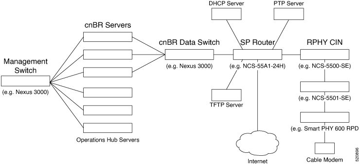
    Simplified cnBR Topology

Prerequisites Required for Deployment

A VMware vSphere ESXi infrastructure with a vCenter server instance is required for end-to-end automated deployment. The SMI Deployer Cluster Manager and Cisco Operations Hub cluster nodes run as virtual machines.

A generalized Cisco cnBR deployment with the Cisco Operations Hub hosted in a VMware cluster is depicted in the following image:
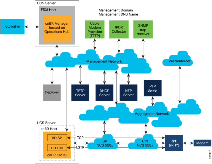
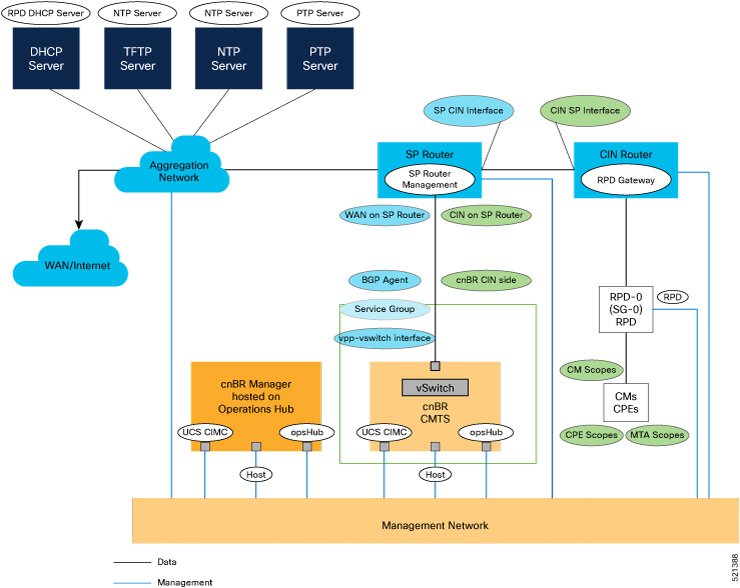
Figure 2. cnBR Deployment in a VMware Cluster
cnBR Deployment in a VMware Cluster
The VMware network topology in the following image is for a VLAN configuration:
Figure 3. VLAN Configuration with VMware Network Topology
VLAN Configuration with VMware Network Topology
The necessary IP addresses and networks that are mapped in the diagram are described in the following sections:
  • Networks

    The following table provides guidance for the networks that are needed in the management, WAN, and CIN routing domains:

    Network Information for Routing Domains

    Table 5. Network Information for Routing Domains

    Name

    Subnet Mask

    Function

    Management

    • 2 addresses for each cluster

    • Operations Hub/cnBR UCS

    • 1 for each cluster

    • 1 for each service device

    Management

    CIN

    Network requirements for each customer

    Connection RPD and CCAP core

    WAN

    Network requirements for each customer

    Internet access for CPE

    cnBR CIN side

    Network requirements for each customer

    -

    BGP network to SP router

    Network requirements for each customer

    Management

    Network for data

    Network requirements for each customer

    -

    SG IP cnBR side

    Network requirements for each customer

    The peer IP for Service Group on cnBR

    RPD address pool

    Customer selected

    DHCP scope for RPD sized to cover total number of RPDs.

    DHCP scope for CM

    Customer selected

    -

    DHCP scope for CPE

    Customer selected

    -

    DHCP scope for MTA

    Customer selected

    -

    You must provide domain and DNS name for the management network.

  • Device Addresses

    The followings tables provide information on the IP address that is needed for device and router interfaces.

    • Management IP Address: Each management interface that is listed in the following table requires 1 IP address:

      Management Interface and Associated IP Addresses

      Table 6. Management Interface and Associated IP Addresses

      Device name

      Number of Addresses

      CIMC cnBR

      1 per cnBR UCS

      Host OS cnBR

      1 per cnBR UCS

      cnBR VIP

      1 per cnBR Cluster

      CIMC Operations Hub

      1 per Operations Hub UCS

      ESXi Operations Hub

      1 per Operations Hub UCS

      Operations Hub

      1 per Operations Hub VM

      Operations Hub VIP

      1 per Operations Hub Cluster

      Deployer

      1

      vCenter

      1

      SP router

      1

      CIN router

      1

    • DOCSIS Network Addresses: The following table lists the DOCSIS network-related information:

      DOCSIS Network-Related Information

      Table 7. DOCSIS Network-Related Information

      Device Name

      Network Name

      Description

      Number of Addresses

      SP router to CIN

      CIN

      SP connection to CIN router

      1

      CIN router to SP

      CIN

      CIN connection to SP router

      1

      SP router to WAN

      WAN

      SP connection to WAN/Internet

      1

      RPD Gateway

      CIN

      RPD gateway router Address

      1

      cnBR CIN side

      CIN

      cnBR connection to CIN

      Customer specific

      BGP Agent

      WAN

      WAN router BGP Agent IP

      Customer specific

      Service Group

      WAN

      Service Group WAN IP

      Customer specific

      WAN on SP Router

      WAN

      SP connection to WAN network

      Customer specific

    • Customer Provisioned Services: The following table lists the various customer services:

      Customer Provisioned Services

      Table 8. Customer Provisioned Services

      Service

      Notes

      DHCP

      Needed for both RPD and subscriber devices

      TFTP

      RPD only uses it during software upgrade

      TOD

      Time of day clock

      PTP

      One connection that is required for the cnBR and for each RPD

      NTP

      Network Time Protocol Server

      DNS

      Domain Name Server

Prepare Supporting Software Components

To prepare the Cisco Unified Computing System (UCS) servers for software installation, you must do the following.

Cisco UCS Server Installation

Procedure


Step 1

Rack mount the servers. See Cisco UCS C220 M5 Server Installation and Service Guide.

Step 2

Ensure that both power supplies are connected on each server, and power on the servers.

Step 3

Connect the following network cables:

  • For Cisco Integrated Management Controller (CIMC), use the 1Gb Ethernet dedicated management port.

  • For Cisco cnBR Host Operating System Management, use Ethernet port 1 of the Dual 1Gb/10Gb Intel X550T on board NIC.

  • For Cisco cnBR Data, if the 40G NIC is used, connect port 1 of the Intel XL710 40G NIC in PCIe Slot 1 to the SP Router/Leaf Switch using Cisco QSFP-40G-SR4. If the 100G NIC is used, connect port 1 of the Mellanox UCSC-P-M5D100GF 100G NIC in PCIe Slot 1 to the SP Router/Leaf Switch using Cisco QSFP-100G-SR4.

Step 4

Connect the UCS Kernel-based Virtual Machine (KVM) console adapter or connect a keyboard and monitor directly to the server.

Step 5

Configure CIMC through the KVM console and update the Network Settings.


Update Firmware

Procedure


Download the latest Hardware Update Utility for the UCS C220 M5 Server from Cisco's Software Download site and use it to update the CIMC, BIOS, and Device Firmware for Storage Controllers, Network Adapters, SSDs, and other components.


Load Cisco cnBR Optimized BIOS Configuration

Procedure


Step 1

Create a new json file "cnbr_perf.json" and add the following structure.

Cisco cnBR Optimized BIOS profile config for C220 M5 Servers
{  
   "name":"Perf_M5",
   "description":"",
   "tokens":{  
      "EnhancedIntelSpeedStep":"Enabled",
      "IntelTurboBoostTech":"Enabled",
      "IntelHyperThread":"Disabled",
      "CPUPerformance":"Enterprise",
      "ExecuteDisable":"Enabled",
      "IntelVTD":"Enabled",
      "ProcessorC1E":"Disabled",
      "ProcessorC6Report":"Disabled",
      "PsdCoordType":"HW ALL",
      "CpuEngPerfBias":"Performance",
      "PwrPerfTuning":"BIOS",
      "CpuHWPM":"HWPM Native Mode",
      "WorkLdConfig":"IO Sensitive",
      "SelectMemoryRAS":"Maximum Performance",
      "SNC":"Disabled",
      "XPTPrefetch":"Enabled",
      "DcuIpPrefetch":"Enabled",
      "PatrolScrub":"Disabled"
   }
}
Step 2

Load the optimized Cisco cnBR BIOS configuration into the system using "cnbr_perf.json".

Step 3

Save a backup of the current BIOS settings.

Step 4

Select the new profile "Perf_M5" and activate it.


Configure Boot Drives

Procedure


Step 1

Enable the Cisco MSTOR Boot Optimized M.2 RAID Controller.

Step 2

Create a RAID 1 virtual drive from 2 x M.2 SSD Drives.

Step 3

Set Stripe Size to 64KB


Configure Data Drives

Procedure


Step 1

Enable Cisco 12G SAS Modular RAID Controller.

Step 2

Create a RAID 5 enabled virtual drive using 4 x SSDs.

Step 3

Set Stripe Size to 64KB.

Step 4

Set Write Cache Policy to Write Back with Good BBU.


Configure UCS Servers for Hosting Operations Hub

Complete the following steps to configure UCS servers for hosting Cisco Operations Hub.

Install VMware ESXi

Procedure

Step 1

Download the Cisco custom image for ESXi 6.5 U3 GA Install CD ISO from VMware.

Step 2

Install VMware ESXi 6.5 Update 3 on the M.2 RAID 1 Virtual Drive (Boot Drive).

Step 3

Use the Cisco Custom ISO - VMware_ESXi_6.5.0_13932383_Custom_Cisco_6.5.3.1.iso

Step 4

Set a password for the root user following the installation process.

Step 5

Reboot the VMware ESXi host following the installation process and execute the steps in Reboot VMware ESXi Host and Set Boot Device.


Reboot VMware ESXi Host and Set Boot Device

Procedure

Step 1

Interrupt the boot process with the F2 key after the host resets and boot into the BIOS.

Step 2

Under the Boot Options tab, set Boot Option #1 to the UEFI target - VMware ESXi.

Step 3

Disable all other boot options.

Step 4

Save changes and exit.

Step 5

Confirm the host boots directly into VMware ESXi.


Configure VMware ESXi Host Management Networking

Procedure

Step 1

Log into the VMware ESXi host through the Direct Console User Interface (DCUI) with the root account.

Note 

For Cisco cnBR PID Servers, use the password received from your Cisco representative as part of your Cisco cnBR order.

Step 2

Configure the management network.

  1. Update IP configuration.

  2. Update DNS configuration.

  3. Update custom DNS suffixes.

  4. Update VLAN ID if required.


Add ESXi Hosts to VMware vCenter Server

In VMware vCenter:
Procedure

Step 1

Create a new, dedicated cluster for Cisco cnBR.

Note 

Do not enable DRS or any HA features.

Step 2

Add each new Cisco cnBR ESXi Host to the new Cisco cnBR cluster.


Configure and Enable Required ESXi Host Features

Procedure

Step 1

Configure time on the host.

  1. Enable NTP.

Step 2

Apply ESXi host licenses.

Step 3

Enable PCI Pass-through on all four Intel XL710 40G QSFP+ ports(requires host reboot).

Step 4

Create a new datastore on the data drive storage device.

Note 

By default, Cisco cnBR PID servers have a datastore created and PCI Pass-through enabled.


Configure Virtual Machine Networking

Procedure

Step 1

Ensure VMware vSwitch connectivity to the physical switch.

Step 2

Create a PortGroup and a VMware vSwitch for the Kubernetes Cluster Node VM MGMT Network.


Deployment of cnBR and Operations Hub

Feature History

Feature Name

Release Information

Feature Description

Bare-metal support

Cisco cnBR 21.2

With the introduction of Bare Metal support, all the required software and applications for Cisco cnBR and Cisco Operations Hub installation are provided in a single release package. This provides for a simplified deployment and configuration, and eliminates any dependency on external software repositories.

Cisco cnBR supports the offline installation of the SMI Cluster Manager, Cisco Operations Hub, and Cisco cnBR clusters.

All software and applications that are required for Cisco cnBR and Cisco Operations Hub installation are provided in a single release package. This eliminates any dependency on external software repositories. All system components including the SMI Deployer Cluster Manager, Cisco Operations Hub cluster, and Cisco cnBR cluster, can be created from scratch in offline or an air-gapped environment.

Cisco cnBR and Cisco Operations Hub product tar files containing all necessary Helm charts and Docker container images are included in the release package. The product tar files are imported into the SMI Deployer during the installation process.

The installation is started from a staging server using the Autodeploy utility that is packaged in the cnBR release bundle. The staging server can be any host running docker that has access to the physical and virtual system infrastructure.

Through Autodeploy, the SMI Deployer VM is created first and in turn installs the Cisco cnBR and the Cisco Operations Hub clusters. The Autodeploy app running on the staging server must be able to reach the following components for a proper, automated end-to-end deployment:

  • For the creation of the SMI Deployer Cluster Manager VM:

    • vCenter Server server instance used to create and manage the SMI Deployer VM

    • VM MGMT Network Interface of the SMI Deployer Cluster Manager

  • For the installation and verification of Cisco cnBR clusters:

    • Cisco IMC Interface of each UCS C220 M5 Server in the Cisco cnBR cluster

    • Host Operating System Management Interfaces of all Cisco cnBR cluster nodes

    • Primary Virtual IP of each Cisco cnBR cluster

  • For the installation and verification of the Cisco Operations Hub cluster:

    • vCenter instance used to create and manage the Cisco Operations Hub cluster node VMs

    • Guest Operating System Virtual Network Management Interface of all Cisco Operations Hub cluster node VMs

    • Primary Virtual IP of each Cisco Operations Hub cluster

Once created, the SMI Deployer VM must be able to access:

  • For the installation and management of Cisco cnBR clusters:

    • Cisco IMC Interface of each UCS C220 M5 Server in the Cisco cnBR cluster

    • Host Operating System Management Interfaces of all Cisco cnBR cluster nodes

    • Primary Virtual IP of each Cisco cnBR cluster

  • For the installation and management of Cisco Operations Hub clusters:

    • vCenter instance used for the Cisco Operations Hub cluster nodes

    • Guest Operating System Virtual Network Management Interface of all Cisco Operations Hub cluster node VMs

    • Primary Virtual IP of each Cisco Operations Hub cluster

Prepare the Staging Server

Complete the following steps to prepare the staging server:

Before you begin

Ensure that you have a staging server setup with the following prerequisites:

Procedure


Step 1

Untar the Cisco cnBR release bundle.

In an offline deployment scenario, you must verify the authenticity and integrity of the image before the installation and deployment. The verification script verifies the image automatically through both online (if public network connection is available) and offline mode.

A corrupted or tampered image can lead to an image verification failure. Discard the image and contact the Cisco Customer Support to get the authentic image.

  1. Extract the Cisco cnBR release bundle. Untar the cnbr-installer-.SPA.tgz signed release bundle as shown:

    
    ~/staging$ tar xvzf cnbr-installer-<release-version-tag>.SPA.tgz
      cnbr-installer-<release-version-tag>.tgz   # cnBR release bundle
      isign/                                     # folder with image verification content
      isign/cnbr-installer-<release-version-tag>.tgz.signature
      isign/CNBR-BUNDLE_pubkey.der
      isign/cisco_x509_verify_release.py3
      isign/CNBR_IMAGE_SIGN-CCO_RELEASE.cer                                    
      explode-cnbr                               # script to be used to verify the image signature and untar the cnbr-installer-<release-version-tag>.tgz
      cnbr-verify-image.tar                      # cnbr verification image, will be automatically loaded through explode-cnbr
  2. Verify and extract the Cisco cnBR image

    • Run the following script to verify the image. cnbr-installer-xxx.tgz untars automatically if the verification is successful. A successful verification is as follows:

      
      ~/staging$ ./explode-cnbr
      Verifying cnbr-installer-<release-version-tag>.tgz
      Verified OK
      Extracting cnbr-installer folder...
      x cnbr-installer-<release-version-tag>/
      x cnbr-installer-<release-version-tag>/isign/
      x cnbr-installer-<release-version-tag>/isign/autodeploy_<version-tag>.tar.signature
      x cnbr-installer-<release-version-tag>/isign/innerspace.der
      x cnbr-installer-<release-version-tag>/isign/cluster-manager-docker-deployer_<version-tag>.tar.signature
      x cnbr-installer-<release-version-tag>/isign/crcam2.der
      x cnbr-installer-<release-version-tag>/isign/CCMTS_IMAGE_SIGN-CCO_RELEASE.cer
      x cnbr-installer-<release-version-tag>/isign/ccmts-customization_<version-tag>.tar.signature
      x cnbr-installer-<release-version-tag>/isign/cee-<version-tag>.tar.signature
      x cnbr-installer-<release-version-tag>/isign/crcam2.cer
      x cnbr-installer-<release-version-tag>/isign/opshub-stable.tar.signature
      x cnbr-installer-<release-version-tag>/isign/OPSHUB_IMAGE_SIGN-CCO_RELEASE.cer
      x cnbr-installer-<release-version-tag>/isign/innerspace.cer
      x cnbr-installer-<release-version-tag>/isign/cluster-deployer-<version-tag>.tar.signature
      x cnbr-installer-<release-version-tag>/isign/cnbr-stable.tar.signature
      x cnbr-installer-<release-version-tag>/isign/CNBR-IMAGE_pubkey.der
      x cnbr-installer-<release-version-tag>/isign/cnbrmanager-stable.tar.signature
      x cnbr-installer-<release-version-tag>/isign/OPSHUB-IMAGE_pubkey.der
      x cnbr-installer-<release-version-tag>/isign/SMI-IMAGE_pubkey.der
      x cnbr-installer-<release-version-tag>/isign/CLUSTER_MANAGER_IMAGE_SIGN-CCO_RELEASE.cer
      x cnbr-installer-<release-version-tag>/examples/
      x cnbr-installer-<release-version-tag>/examples/multinode-opshub-config.yaml
      x cnbr-installer-<release-version-tag>/examples/day1_config_mn.yaml
      x cnbr-installer-<release-version-tag>/examples/deployer-sample-config.yaml
      x cnbr-installer-<release-version-tag>/examples/multinode-cnbr-config.yaml
      x cnbr-installer-<release-version-tag>/examples/multinode-opshub-multi-nic-config.yaml
      x cnbr-installer-<release-version-tag>/examples/aio-cnbr-config.yaml
      x cnbr-installer-<release-version-tag>/examples/day1_config_aio.yaml
      x cnbr-installer-<release-version-tag>/examples/multinode-cnbr-bare-metal-config.yaml
      x cnbr-installer-<release-version-tag>/examples/l3_template.json
      x cnbr-installer-<release-version-tag>/examples/multinode-cnbr-expansion-link-redundancy-config.yaml
      x cnbr-installer-<release-version-tag>/examples/aio-opshub-config.yaml
      x cnbr-installer-<release-version-tag>/examples/sg_template_4x4.json
      x cnbr-installer-<release-version-tag>/examples/multinode-cnbr-expansion-config.yaml
      x cnbr-installer-<release-version-tag>/docker-images/
      x cnbr-installer-<release-version-tag>/docker-images/ccmts-customization_<version-tag>.tar
      x cnbr-installer-<release-version-tag>/cluster-deployer-<version-tag>.tar
      x cnbr-installer-<release-version-tag>/deploy
      x cnbr-installer-<release-version-tag>/smi-install-disk.iso
      x cnbr-installer-<release-version-tag>/offline-products/
      x cnbr-installer-<release-version-tag>/offline-products/cee-<version-tag>.tar
      x cnbr-installer-<release-version-tag>/offline-products/opshub-stable.tar
      x cnbr-installer-<release-version-tag>/offline-products/cnbr-stable.tar
      x cnbr-installer-<release-version-tag>/offline-products/cnbrmanager-stable.tar
      x cnbr-installer-<release-version-tag>/README.md
      x cnbr-installer-<release-version-tag>/utility-images/
      x cnbr-installer-<release-version-tag>/utility-images/cluster-manager-docker-deployer_<version-tag>.tar
      x cnbr-installer-<release-version-tag>/utility-images/autodeploy_<version-tag>.tar
Step 2

After the cnbr-installer-.SPA.tgz is verified:


> cd cnbr-installer-<release-version-tag> 
The directory, staging/cnbr-installer-\<release-version-tag\>, is referred to as staging or install directory. The directory has the following content:
~/staging/cnbr-installer-<version-tag>$ tree
.
├── certs
    ├── client_certificates
    └── metrics
├── cluster-deployer-<version-tag>.tar
├── deploy
├── docker-images
│   └── ccmts-customization_<version-tag>.tar
├── examples
│   ├── aio-opshub-config.yaml    # For Experimental, Lab/Demo purpose only
│   ├── day1_config_mn.yaml
│   ├── deployer-sample-config.yaml
│   ├── l3_template.json
│   ├── multinode-cnbr-bare-metal-config.yaml
│   ├── multinode-cnbr-config.yaml
│   ├── multinode-cnbr-expansion-config.yaml
│   ├── multinode-cnbr-expansion-link-redundancy-config.yaml
│   ├── multinode-opshub-config.yaml
│   ├── multinode-opshub-multi-nic-config.yaml
│   └── sg_template_4x4.json
├── offline-products
│   ├── cee-<version-tag>.tar
│   ├── cnbrmanager-stable.tar
│   ├── cnbr-stable.tar
│   └── opshub-stable.tar
├── README.md
├── smi-install-disk.iso
└── utility-images
    ├── autodeploy_<version-tag>.tar
    └── cluster-manager-docker-deployer_<version-tag>.tar

7 directories, 22 files

Create the Configuration File

The configuration file is in the standard YAML descriptive language format.

Use the following steps to create the configuration file:

Procedure


Step 1

Configure the environment: Cisco cnBR clusters, Cisco Operations Hub clusters, and the SMI Deployer each require an environment for deployment. The environment configuration defines a deployment domain and can be associated, as required, with one or more deployers or clusters.

For the Deployer and Cisco Operations Hub, the deployment domain is VMware vSphere. The environment configuration must include vCenter access information and vSphere ESXi infrastructure details that are used to create and provision the virtual machines.

For the Cisco cnBR, the deployment domain is bare-metal. The environment configuration includes minimal settings that are applied to the UCS Cisco IMC and the guest operating system of the cluster nodes.

Deployer or Cisco Operations Hub VM-based environment configuration:


environments:
"<<env-name>>":                                    # Environment name                      
        server: "<<XX.XX.XX.XX>>"                      # vCenter Server IP
        username: "<<user-name>>"                      # vCenter username, user will be prompted for the password  
        datacenter: "<<vmware datacenter>>"            # DataCenter Name       
        cluster: "<<vcenter cluster>>"                 # vCenter Cluster Name       
        nics: [ "<<VM Network>>", "<<VM Network1>>" ]  # vCenter nics (port groups)
        nameservers: [ "<<YY.YY.YY.YY>"]               # DNS Servers
        search-domains: [ "<<yourdomain>>" ]           # Search domains
        ntp: "<<yourclock.domain>>"                    # NTP Server
        https-proxy: "<<http://proxyhost.domain:port>>"
        no-proxy: "<<127.0.0.1,localhost>>"
cnBR Environment config:

"<<env-name>>":                                    # Environment name, typically "ucs" 
    ntp: "<<yourclock.domain>>"                    # NTP Server
    nameservers: [ "<<YY.YY.YY.YY>"]               # DNS Servers
    search-domains: [ "<<yourdomain>>" ]           # Search domains
Step 2

Configure the deployer: The deployer configuration requires an environment and settings that are used for the ESXi VM and the guest operating system:


deployers:
  "<<deployer3-test>>":                              # deployer VM name
      environment: "<<vcenter-env>>"                 # reference to vCenter environment  
      address: "<<XX.XX.XX.XX/prefix_len>>"          # SSH-IP of the VM in CIDR format
      gateway: "<<XX.XX.XX.XX>>"                     # Gateway for the VM
      ingress-hostname: "<<host.domain>>"            # Custom ingress hostname for the deployer - FQDN (Optional)
      username: "<<user-name>>"                      # Deployer VM username, user will be prompted for the password  
      # SSH private-key-file with path relative to the staging directory
      # Key will be auto-generated, if one if not provided
      private-key-file: "<<cmts.pem>>"                     
      host: "<<XX.XX.XX.XX>>"                        # Server IP where Deployer VM is hosted
      datastore: "<<datastore1>>"                    # Datastore for the Deployer VM
When you configure a custom ingress hostname for the deployer, ensure that the following entries are in the DNS:

<host.domain>
charts.<host.domain>
files-offline.smi-cluster-deployer.<host.domain>
deployer-ui.smi-cluster-deployer.<host.domain>
cli.smi-cluster-deployer.<host.domain>
restconf.smi-cluster-deployer.<host.domain>
docker.<host.domain>
Step 3

Configure the cluster: Both Cisco cnBR and Cisco Operations Hub cluster configurations must have at least one environment and one deployer that is defined in order to be deployed.

A cluster can be one of the following types:

  • Multi-Node Cisco cnBR

  • Multi-Node Cisco Operations Hub

Note 
  • Single-Node Cisco Operations Hub is supported for Lab or Demo purpose only.

  • Single-Node Cisco cnBR clusters are not supported.

Multi-Node cnBR Configuration

  • The Cisco cnBR Multi-Node Cluster config below creates a 3 node bare-metal cnBR cluster

  • Four Management IP Addresses are required = 3 for the Control Plane Nodes + 1 Primary Virtual IP

  • For each control-plane-node below, update the address, cimc ip-address, and cimc username accordingly

cnBR Multi-Node Cluster Configuration:


clusters:
# Name of the cluster
"<<cnbr-multi>>":                                  # cnBR cluster name
    type: "<<cnbr>>"                               # Cluster type 'cnbr'
    environment: "<<ucs-env>>"                     # reference to UCS environment
    ingress-hostname: "<<FQDN>>"                   # Optional ingress-hostname
    gateway: XX.XX.XX.XX                           # Gateway for the Cluster
    username: "<<user-name>>"                      # Cluster username, User will be prompted for the cluster password  
    # SSH private-key-file with path relative to the staging directory
    # Key will be auto-generated, if not provided
    private-key-file: "<<cmts.pem>>"
    ethernet: "<interface-name>>"                  # Kubernetes Host MGMT Interface Name
    primary-vip: "<<XX.XX.XX.XX/prefix_len>>"      # Primary Virtual IP in CIDR format for Multi-Node only
    # Keepalived Virtual Router ID, value must be between 0-255
    # Each Multi-Node cluster of any type on the same MGMT Network must have a unique value configured
    vrouter-id:  "<<value>>"
    control-plane-nodes:
        -  address: "<<XX.XX.XX.XX/prefix_len>>"
           cimc: {"ip-address": "<<XX.XX.XX.XX>>", "username": "<<cimc-user-name>>"}
        -  address: "<<XX.XX.XX.XX/prefix_len>>"
           cimc: {"ip-address": "<<XX.XX.XX.XX>>", "username": "<<cimc-user-name>>"}
        -  address: "<<XX.XX.XX.XX/prefix_len>>"
           cimc: {"ip-address": "<<XX.XX.XX.XX>>", "username": "<<cimc-user-name>>"}

Multi-Node and Single Node Operations Hub

  • The Reference Multi-Node Configuration below distributes the Cluster Node VMs across three ESXi Hosts evenly with proper compute resource reservation

  • 13 Management IP Addresses total = 12 for the Cluster Nodes + 1 Primary Virtual IP

  • For each node below, update the k8s ssh-ip, VMware data store, and VMware host accordingly


clusters:
# Name of the cluster
"<<opshub-multi>>":                                # Operations Hub cluster name
    type: "<<opshub>>"                             # Cluster type 'opshub'
    environment: "<<vcenter-env>>"                 # reference to vCenter environment
    gateway: XX.XX.XX.XX                           # Gateway for the Cluster
    username: "<<user-name>>"                      # Cluster username, User will be prompted for the cluster password  
    # SSH private-key-file with path relative to the staging directory
    # Key will be auto-generated, if not provided
    private-key-file: "<<cmts.pem>>"                     
    primary-vip: "<<XX.XX.XX.XX/prefix_len>>"      # Primary Virtual IP in CIDR format for Multi-Node only
    # Keepalived Virtual Router ID, value must be between 0-255
    # Each Multi-Node cluster of any type on the same MGMT Network must have a unique value configured
    vrouter-id:  "<<value>>"
  
  # For Multi-Node only
  nodes:
    -  host: "<<XX.XX.XX.182>>".                  # ESXi Host IP Address or Name in vCenter Cluster
       # IP addresses assigned to control-plane-node, etcd, infra and docsis/ops nodes respectively
       addresses: [ "<<XX.XX.XX.187>>", "<<XX.XX.XX.172>>", "<<XX.XX.XX.169>>", "<<XX.XX.XX.190>>"]
       datastore: "<<XX.XX.XX.182-datastore1>>"
    -  host: "<<XX.XX.XX.176>>"
       addresses: [ "<<XX.XX.XX.188>>", "<<XX.XX.XX.173>>", "<<XX.XX.XX.170>>", "<<XX.XX.XX.191>>"]
       datastore: "<<XX.XX.XX.176-datastore1>"
    -  host: "<<XX.XX.XX.184>>"
       addresses: [ "<<XX.XX.XX.189>>", "<<XX.XX.XX.174>>", "<<XX.XX.XX.171>>", "<<XX.XX.XX.192>>"]
       datastore: "<<XX.XX.XX.184-DataStore1>>"
       
  # For Single-Node cluster [ Only supported, for Lab/Demo purpose for OperationsHUB ]
  nodes:
    -  host: "<<XX.XX.XX.182>>"                   # ESXi Host IP Address or Name in vCenter Cluster
       addresses: [ "<<XX.XX.XX.187/prefix_len>>"]
       datastore: "<<XX.XX.XX.182-datastore1>>"

When you configure a custom ingress hostname for a cluster, ensure that the following entries are in the DNS:

  • For Cisco cnBR
    
    <host.domain>
    cli.ccmts-infra-ops-center.<host.domain>
    documentation.ccmts-infra-ops-center.<host.domain>
    restconf.ccmts-infra-ops-center.<host.domain>    
    docs.cee-data-product-documentation.<host.domain>
    cli.cee-data-ops-center.<host.domain>
    documentation.cee-data-ops-center.<host.domain>
    prometheus-hi-res.cee-data-cnat-monitoring.<host.domain>
    restconf.cee-data-ops-center.<host.domain>
    show-tac-manager.cee-data-smi-show-tac.<host.domain>    
    grafana.<host.domain>
  • For Cisco Operations Hub:
    
    <host.domain>
    cli.opshub-data-ops-center.<host.domain>
    documentation.opshub-data-ops-center.<host.domain>
    restconf.opshub-data-ops-center.<host.domain>
    docs.cee-data-product-documentation.<host.domain>
    cli.cee-data-ops-center.<host.domain>
    documentation.cee-data-ops-center.<host.domain>
    prometheus-hi-res.cee-data-cnat-monitoring.<host.domain>
    restconf.cee-data-ops-center.<host.domain>
    show-tac-manager.cee-data-smi-show-tac.<host.domain>
    restconf.cnbrmanager-data-ops-center.<host.domain>

Deploy the Cluster

Procedure


Deploy the cluster by using the following command:

~/cnbr-installer-<release-version-tag>$ ./deploy -c <config_file>

The Cluster Manager is deployed first, before deploying any cluster. To deploy more clusters, run the command with the corresponding configuration files.


Deployment Example Configurations

Feature History

Table 9. Feature History

Feature Name

Release Information

Feature Description

Second NIC configuration on the Cisco Operations Hub for cable modem data

Cisco cnBR 20.3

You can configure second NIC on the Cisco Operations Hub cluster that connects to CIN network, allowing the Cisco Operations Hub to poll cable modem data such as SNR and TX/RX power.

Multiple NIC configuration on the Cisco Operations Hub for cable modem data

Cisco cnBR 21.2

You can configure multiple NIC on the Cisco Operations Hub cluster that connects to CIN network, allowing the Cisco Operations Hub to poll cable modem data such as SNR and TX/RX power.

Example configuration files are included with the installation package and are located in the examples directory. You can copy and modify the required example configuration files.

Ensure that you have gone through the Configuring your environment and Configuring your deployer topics.

  • Sample Deployer Configuration

    The following is a sample configuration to deploy the cluster manager.

    
    environments:
      "vcenter-env":
          server: "XX.XX.XX.XX"
          username: "vCenter username"                        
          datacenter: "vmware datacenter"
          cluster: "vmware cluster"
          nics: [ "VM Network" ]
          nameservers: [ "DNS1", "DNS2"]
          search-domains: [ "yourdomain" ]
          ntp: "yourclock.yourdomain"
          https-proxy: "http://proxyhost.domain:port"
          no-proxy: "127.0.0.1,localhost"
    
    deployers:
      "deployer3-test":
          environment: "vcenter-env"
          address: "XX.XX.XX.194/prefix_len"
          gateway: "XX.XX.XX.129"
          username: "cloud-user"
          private-key-file: "cmts.pem"
          host: "XX.XX.XX.184"
          datastore: "XX.XX.XX.184-DataStore1"
  • Multi-Node cnBR Configuration

    Define the cluster configuration as shown:

    
    clusters:
      "cnbr-mnode":
          type: "cnbr"
          environment: "ucs"
          primary-vip: "XX.XX.XX.193/prefix_len"
          username: "cloud-user"
          private-key-file: "cmts.pem"
          ethernet: "eno1"
          vrouter-id:  "95"
          gateway: XX.XX.XX.129
          control-plane-nodes:
            -  address: "XX.XX.XX.187/24"
               cimc: {"ip-address": "XX.XX.XX.125", "username": "admin"}
            -  address: "XX.XX.XX.188/24"
               cimc: {"ip-address": "XX.XX.XX.126", "username": "admin"}
            -  address: "XX.XX.XX.189/24"
               cimc: {"ip-address": "XX.XX.XX.127", "username": "admin"}       
  • Multi-Node Operations Hub Configuration

    Define the cluster configuration as shown:

    
    clusters:
      "opshub-mnode":
          type: "opshub"
          environment: "vcenter-env"
          primary-vip: "XX.XX.XX.193/prefix_len"
          gateway: XX.XX.XX.129
          vrouter-id:  "193"
          username: "cloud-user"
          private-key-file: "cmts.pem"
          size: "normal"  # By default, multi-node Operations Hub deployment config size is 'small', use 'normal' for deployment with higher configuration requirements.
          nodes:
            -  host: "XX.XX.XX.182"
               datastore: "XX.XX.XX.182-datastore1"
               addresses: [ "XX.XX.XX.187", "XX.XX.XX.172", "XX.XX.XX.169", "XX.XX.XX.190"]
            -  host: "XX.XX.XX.176"
               datastore: "XX.XX.XX.176-datastore1"
               addresses: [ "XX.XX.XX.188", "XX.XX.XX.173", "XX.XX.XX.170", "XX.XX.XX.191"]
            -  host: "XX.XX.XX.184"
               datastore: "XX.XX.XX.184-DataStore1"
               addresses: [ "XX.XX.XX.189", "XX.XX.XX.174", "XX.XX.XX.171", "XX.XX.XX.192"]
  • Multi-Node Operations Hub Configuration with Custom Ingress Hostname and 2nd Network Interface on Ops Nodes

    Define the cluster configuration as shown:

    
    clusters:
      "opshub-mnode":
          type: "opshub"
          environment: "vcenter-env"
          primary-vip: "XX.XX.XX.193/prefix_len"
          gateway: XX.XX.XX.129
          vrouter-id:  "193"
          ingress-hostname: "opshub1.cisco.com"
          username: "cloud-user"
          private-key-file: "cmts.pem"
          size: "normal"  # By default, multi-node Operations Hub deployment config size is 'small', use 'normal' for deployment with higher configuration requirements.
          nodes:
            -  host: "XX.XX.XX.182"
               datastore: "XX.XX.XX.182-datastore1"
               addresses: [ "XX.XX.XX.187", "XX.XX.XX.172", "XX.XX.XX.169", "XX.XX.XX.190"]
               nics: [ "OpsHub7-Remote-Query" ]
               ops:
                 interfaces:
                   - addresses: [ "5.202.0.40/24" ]
                     routes:
                       - {dest: [ "5.225.0.0/16" ], nhop: "5.202.0.1" }
            -  host: "XX.XX.XX.176"
               datastore: "XX.XX.XX.176-datastore1"
               addresses: [ "XX.XX.XX.188", "XX.XX.XX.173", "XX.XX.XX.170", "XX.XX.XX.191"]
               nics: [ "OpsHub7-Remote-Query" ]
               ops:
                 interfaces:
                   - addresses: [ "5.202.0.41/24" ]
                     routes:
                       - {dest: [ "5.225.0.0/16" ], nhop: "5.202.0.1" }               
            -  host: "XX.XX.XX.184"
               datastore: "XX.XX.XX.184-DataStore1"
               addresses: [ "XX.XX.XX.189", "XX.XX.XX.174", "XX.XX.XX.171", "XX.XX.XX.192"]
               nics: [ "OpsHub7-Remote-Query" ]
               ops:
                 interfaces:
                   - addresses: [ "5.202.0.42/24" ]
                     routes:
                       - {dest: [ "5.225.0.0/16" ], nhop: "5.202.0.1" }    
  • Single-Node Operations Hub Configuration

    The Single Node Cluster is not supported for production. It is restricted for use at the Lab.

    Define the cluster configuration as shown:

    
    clusters:
      "opshub-snode":
          type: "opshub"
          environment: "vcenter-env"
          gateway: XX.XX.XX.129
          username: "cloud-user"
          private-key-file: "cmts.pem"
          nodes:
            -  host: "XX.XX.XX.139"
               datastore: "XX.XX.XX.139-datastore1"
               addresses: [ "XX.XX.XX.159/prefix_len" ]        

Deployment Limitations

The following are the deployment limitations in this release:

  • IPv6 addressing is not supported.

  • The config file must comply to YAML syntax. Not conforming to the syntax might cause crash dumps.

  • The configuration file must comply to all mandatory sections and attributes. You might see the autodeploy exit without warnings and errors when mandatory attributes are missing in the configuration file.

  • Limited error and exception handling. When an exception or error occurs, you might see detailed crash dumps.

  • Single node cluster for Cisco Operations Hub is not supported in production. Single Node Cisco Operations Hub clusters are meant for use at the Lab.

Configure Operations Hub

The Cisco Operations Hub allows you to create and configure users.

This section provides details of how to configure the Cisco Operations Hub and to use the UI and APIs.

Access Operations Hub

You can access the Operations Hub home page using the following URL:
https://{Hostname}

Hostname is the Fully Qualified Domain Name (FQDN) of the Cisco Operations Hub cluster, which is configured using the ingress-hostname key of the deployer configuration. When the Cisco Operations Hub cluster is deployed without the ingress-hostname key, the format of the Hostname is {vip}.nip.io, where vip is the virtual IP address of the Cisco Operations Hub cluster.

Customize Login Banner

Feature History

Table 10. Feature History

Feature Name

Release Information

Feature Description

Login Banner Messages

Cisco cnBR 21.2

You can create and display a customized message that appears as a banner on the Cisco Operations Hub login page.

An administrator can create and customize a banner for the Cisco Operations Hub login page.

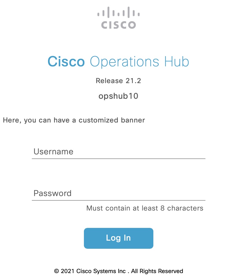
Cisco Operations Hub Login Page

You can also use APIs to customize the banner. For more details, see the Cisco Cloud Native Broadband Router Operations Hub REST API Guide.

To customize the banner, use the following procedure:

Procedure


Step 1

On the Cisco Operations Hub, click the Cisco Operations Hub main menu button.

Step 2

Choose System > Login Banner Message.

Step 3

Enter the message in the text box and click Save.

A maximum of 500 characters are allowed in the banner message text box.

Navigate through Operations Hub

Feature History

Table 11. Feature History

Feature Name

Release Information

Feature Description

New dashboard home page and left navigation menu

Cisco cnBR 21.2

The Metrics & Dashboards page in the cnBR Manager has been renamed Dashboards and promoted to be a top level Cisco Operations Hub main menu item. The Dashboards home page has been updated to include a list of Suggested and Recently viewed dashboards. Additionally, the left navigation menu on the Dashboards page has been streamlined to improve usability.

After the Operations Hub is deployed successfully, you can navigate through the main menu. An overview of the navigation options is provided below.

Overview of the Navigation Options

Main Menu: 1st Level Option

Main Menu: 2nd level

Submenu and Fixed Navigation Items

cnBR Manager

cnBRs: Allows you to perform all cnBR related operations.

  • Inventory: Overview of cnBR clusters.

  • Add cnBR: Add cnBR clusters.

  • Import & Export cnBR: Import and export cnBR configurations.

  • Service Group Operations: Overview of service groups, and allows you to move service groups across nodes.

  • Smart Licensing: cnBR license management operations.

Remote PHY Devices: Allows you to perform all RPD related operations.

  • Inventory: Overview of the RPDs in the network.

  • Add RPD: Add RPD in cnBR.

  • Edit RPD: Edit RPD configuration parameters.

  • Replace RPD: Replace MAC Address of an existing RPD.

  • Delete RPD: Remove a RPD from cnBR.

  • Image Management: View and upload RPD software images.

  • Secure Software Download: Apply software images to RPD.

  • Code Validation Check: View and apply code validation certificates.

  • Cutover RPD: Perform RPD cutover.

Profiles and Templates: Allows you to add, edit and delete cnBR Profiles and Templates.

None

Dashboards: Allows you to view Grafana Dashboards.

None

  • Suggested & Recently Viewed: Launch point of Operations Hub Grafana homepage, including a list of recently viewed dashboards.

  • Find a Dashboard: Search a Grafana dashboard.

  • Advanced: Create new dashboards and folders, navigate to existing folders and import existing dashboards.

API Explorer: Allows you to view Operations Hub and cnBR API list.

None

  • List of Operations Hub and cnBR APIs.

System

Logs: Allows you to view and manage Logs.

  • Audit Dashboard: Dashboard to view Audit Logs.

  • Debug Dashboard: Dashboard to view Debug Logs.

  • Advanced: Advanced configuration options to discover, visualize, and manage Kibana dashboards.

Configuration & Upgrade: Import and export Operations Hub configuration file.

  • Import & Export Configuration: Import and export Operations Hub configuration file.

Login Banner Message: View and configure login banner message for Operations Hub.

None

User Management in Cisco Operations Hub

Cisco Operations Hub provides user management functionality where you can create local users and configure LDAP for external authentication. Refer to the following topics for details on user types and how to configure local and LDAP users.

API User Roles

Operations Hub supports three user roles based on the HTTP actions:

  • api-admin: Allowed http method: GET, POST, PUT, DELETE

  • api-editor: Allowed http method: GET, POST, PUT

  • api-viewer: Allowed http method: GET

By default, the user, admin is already under these three groups.

Configure Local Users

Administrators can perform following user management actions from Systems > Security > Users & Roles.


Note

For users other than admin, User & Roles page isn't visible.


Add User
Procedure

Step 1

On the Cisco Operations Hub, click System > Users & Roles to open the Users & Roles page.

Step 2

Click Add User in the Users & Roles page to open Add User side bar.

Step 3

Fill in the email, role, and password for the new user. Strictly follow the password requirement listed in the side bar.

Force password change on next login option is selected by default. Newly created user must change the password during the first login.

Step 4

Click Add User button to confirm creating the new user.


Edit User
Procedure

Step 1

On the Cisco Operations Hub, click System > Users & Roles to open the Users & Roles page.

Step 2

Select a user and click Edit User in the Users & Roles page to open Edit User side bar.

Step 3

You can change the user role and password expiration period.

Step 4

Click Save when you finish editing.


Remove User
Procedure

Step 1

On the Cisco Operations Hub, click System > Users & Roles to open the Users & Roles page.

Step 2

Select a user and click Remove User in the Users & Roles page, a window pops up.

Step 3

Click Remove in the pop-up window to remove the selected user.


Export
Procedure

Step 1

On the Cisco Operations Hub, click System > Users & Roles to open the Users & Roles page.

Step 2

Click Export in the Users & Roles page to export the content of the user management table.


Filter Users in the User List

You can use the Focus dropdown list and the Role buttons Admin, Editor, and Viewer to filter the users in the user list based on password status and user role.

View Session History
Procedure

Step 1

On the Cisco Operations Hub, click System > Users & Roles to open the Users & Roles page.

Step 2

Click a user name in the Users & Roles page to open User Details side bar.

Step 3

Select Sessions History tab to view the login/logout history of the user.


Change Password

You can change the password:

  • from the Cisco Operations Hub main menu by clicking the user name and updating the password in the My Account page.

  • from the alert banner. Alert banner appears 30 days before password expiry. You can change your password by clicking the link in the alert banner. If your password expires, reset the password during next login.

Configure LDAP

Feature History

Table 12. Feature History

Feature Name

Release Information

Feature Description

Integration with LDAP Server

Cisco cnBR 21.3

This feature allows you to use existing LDAP credentials to log in Cisco Operations Hub and configure the LDAP parameters.

Local authentication is enabled by default. Administrators can change the authentication method to LDAP in Systems > Authentication.


Note

LDAP configuration page is visible to admin users only.


To configure LDAP, fill in the following fields.

LDAP Parameters

Description

LDAP Server URL

URL of the LDAP server.

Base Domain Name

Domain name as configured on your LDAP server.

LDAP User Name Domain

Validate the user name against the domain controller.

LDAP Filter

Specify a subset of data items in an LDAP data type.

LDAP Group Attribute

List of comma-separated LDAP attributes on a group object that can be used in a user member attribute.

LDAP Group Mapping

Map LDAP group to Operations Hub role.

Using REST APIs

This section explains how you can use REST APIs.

Procedure


Step 1

Create a user.

Use the procedure from the User Management in Cisco Operations Hub section.

Step 2

Call auth REST API to create token.

Encode the username and password with base 64. Fill the encode output into the Authentication Header.

Example:

User: admin
Password: bell

Get the Base64 under Linux: echo -n 'admin:lab' | base64
Base64 encode output: YWRtaW46bGFi

curl -X POST "https://{Hostname}/api/auth/v1/token" -H  "accept: application/json" -H  "authorization: Basic YWRtaW46bGFi"

Response code: 201
Response body
{
"access_token": "eyJhbGciOiJIUzI1NiIsInR5cCI6IkpXVCJ9.eyJyb2xlIjoiYXBpLWFkbWluIiwic2FsdCI6IlViQ2daamt
IWHd6RUNzS1EiLCJleHAiOjE1NjQ2NTA2MTd9.x7ccHcOn6fLvHc_ajLJxQEY1ftvR1ZaJH9K_YZx1ues",
"refresh_token": "lYYtZqgVhnsnBJgSHbigRzeEaLnWziMpHJKVzgHA",
"refresh_token_expire": 1567221017,
"token_type": "jwt"
}
Step 3

With this token, call other REST APIs.

Example:

Call REST API to get the Cisco cnBR list:
curl -X GET "https://opshub1.cisco.com/api/manager/v1/cmts" -H  "accept: application/json" -H
  "Authorization: Bearer eyJhbGciOiJIUzI1NiIsInR5cCI6IkpXVCJ9.eyJyb2xlIjoiYXBpLWFkbWluIiwic2FsdCI6IlV
iQ2daamtIWHd6RUNzS1EiLCJleHAiOjE1NjQ2NTA2MTd9.x7ccHcOn6fLvHc_ajLJxQEY1ftvR1ZaJH9K_YZx1ues"

Response code:200
Response body
{
  "cluster_list": [
    {
      "cluster-id": "cnbr1.cisco.com",
      "cmts-name": "test",
      "namespace": "ccmts-infra",
      "ingress-host-name": "cnbr1.cisco.com"
    }
  ]
}

Configure TLS Certificate

When Cisco Operations Hub is deployed, a self-signed certificate is automatically created and used for TLS connections. You can replace the self-signed certificate with a CA signed certificate through the Cluster Manager CLI.


Note

If you replace the Cisco Operations Hub self-signed TLS certificate, you must update the cert-api-ingress secret-name in two Kubernetes (K8s) namespaces: opshub-data and cnbrmanager-data. In this case, provide the CA-signed certificate and the private key that is associated with the certificate.


The following example shows how to make the required changes. This example does not show the certificate or the private-key entries. Make sure that you include those:


product opshub# config terminal
Entering configuration mode terminal
product example deployer(config)# clusters {k8s-cluster-name}
product example deployer(config-clusters-******)# secrets tls opshub-data cert-api-ingress ?
Possible completions:
  certificate   Path to PEM encoded public key certificate.
  private-key   Private key associated with given certificate.
  <cr>
product example deployer(config-clusters-******)# secrets tls cnbrmanager-data cert-api-ingress ?
Possible completions:
  certificate   Path to PEM encoded public key certificate.
  private-key   Private key associated with given certificate.
  <cr>
product example deployer(config-clusters-******)#commit
product example deployer(config-clusters-******)#exit
After exiting the configuration mode, synchronize the cluster configuration by running the following command:
clusters {k8s-cluster-name} actions sync run

Configure Cisco cnBR Using Autodeployer

You can complete the Cisco cnBR configuration using the Autodeployer.

Complete the following steps:

Procedure


Step 1

Prepare Cisco cnBR configuration.

There are three categories of configuration:

  • General Configuration

    The general configuration specifies details of the Cisco cnBR and Cisco Operations Hub clusters.
    
    opshub :
        ip : 'xx.xx.xx.xx'           # Operations Hub IP address
        ingress-hostname: '<host.domain>'  # Operations Hub ingress hostname - FQDN (Optional: If the <host.domain> is not available, the default cluster ingress <IPAddress>.nip.io is used.)
    cnbr   :
        name : '<name_of_cnbr>'      # Name of the Cisco cnBR cluster to be added to the Operations Hub
        type : 'MUL_NODES'           # cnBR cluster Type : 'MUL_NODES' Multi-Node cluster is only option supported.
        ip   : 'xx.xx.xx.xx'         # cnBR IP address
        ingress-hostname: '<host.domain>'  # cnBR Ingress Hostname - FQDN (Optional: If the <host.domain> is not available, the default cluster ingress <IPAddress>.nip.io is used.)
        number-of-docsis-node: 3   # Total Number of DOCSIS nodes 
  • Mandatory Configuration

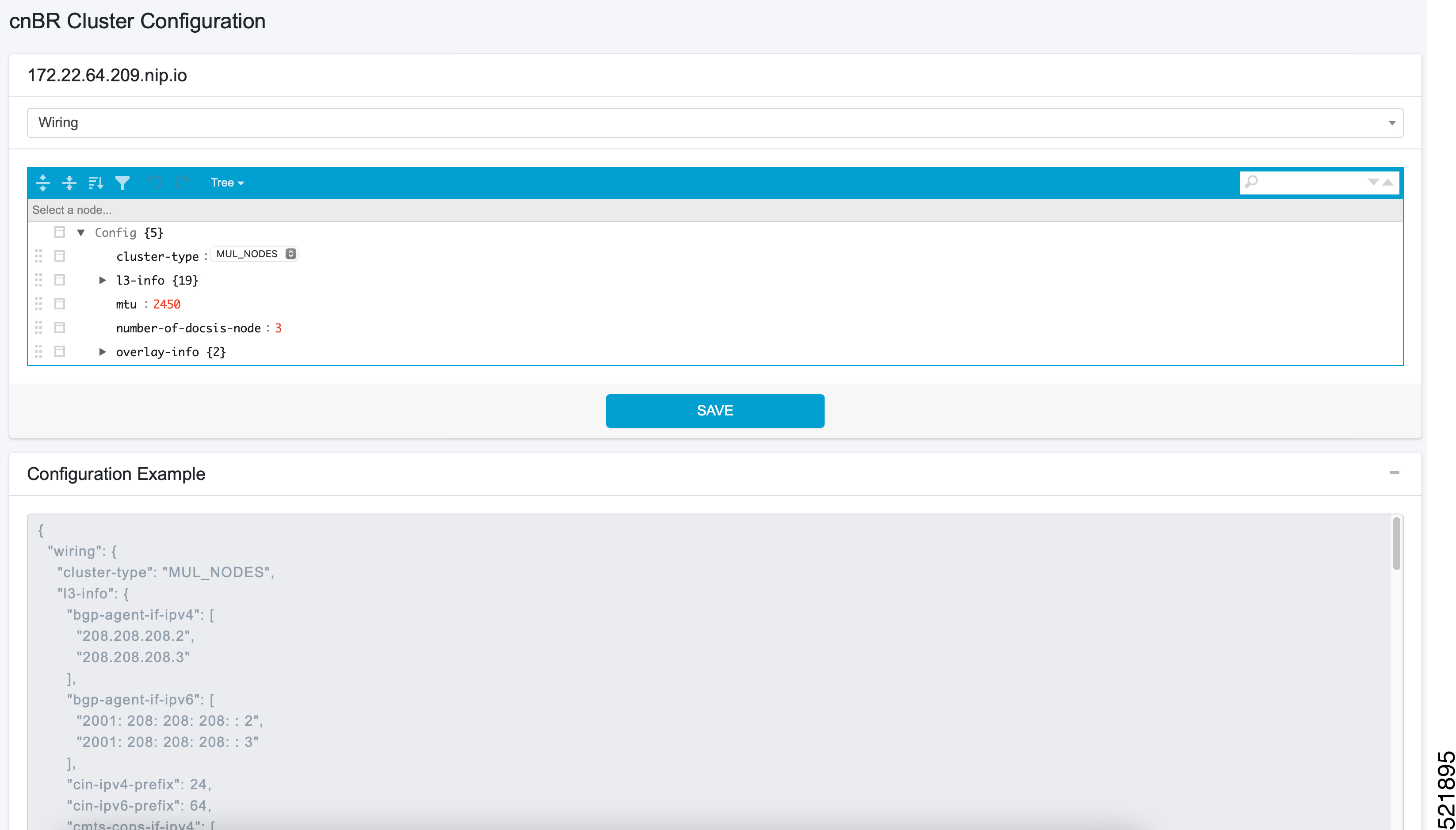
    The mandatory configuration specifies details for the PTP, BGP, CIN, Wiring, templates (SG and L3) and RPD-list.

    Complete the following mandatory configurations:

    • PTP Configuration

      
      ptp :
          v4 :
             domain : <clock-domain>
             master: {'ip':"xx.xx.xx.xx", 'gw':"xx.xx.xx.xx"}
    • BGP Agent Configuration

      
      bgpagent :
          asn : <asn>
          max_hops : <max_hops>
          restart-time : <restart_time>
          stale-path-time: <stale_path_time>
          # list of neighbors ( IPv4 and IPv6 )
          neighbors :
            - {'address' :'xx.xx.xx.xx', 'asn':<asn>}
    • CIN Configuration

      
      # Lists of IPv4 and IPv6 gateways. IPv6 is not supported in this release.
      cin :
          v4 : [ "xx.xx.xx.xx"]
    • Wiring Configuration

      
      wiring :
          # Starting IP address for the range to be used by cnBR internal interfaces
          # Make sure the range does not clash with IP addresses of RPD, COPS, and CCAPCORE
          # IP addresses that will be carved out from this pool to assign to the below interfaces
          #     PTP, VPP-DP and other interface
          cin-start-ip:
             v4 : 'xx.xx.xx.xx'
      
          # SG peer IP, typically its bgp-neighbor IP address but it could be different
          #     dmic-if and relayproxy-if addresses are carved out from the same network
          sg-peer:
             v4 : 'xx.xx.xx.xx'
             v6 : 'xxxx::nnn'  #Needs dummy value even if IPv6 is not enabled. nnn is <0-255>
      
          # ccapcore IP, specified in the DHCP config, where RPD learn ccapcore from
          rphmgr-if:      
             v4 : "xx.xx.xx.xx"
      
          # Packet cable interface IP
          cmts-cops-if:
             v4 : "xx.xx.xx.xx"
      
          # IP addresses to be used by BGP agents running in cnBR
          # AIO needs one and MultiNode needs two as that many instances of bgp agents would be running in the cluster
          bgp-agent-if:
             v4 : ["xx.xx.xx.xx", "xx.xx.xx.xx"]
             v6 : ["xxxx::xxxx", "xxxx::xxxx"]  #Needs dummy values even if IPv6 is not enabled.
      
          # CIN Prefix
          cin-prefix:
             v4 : <prefix_len>
             v6 : <prefix_len> #Needs dummy value even if IPv6 is not enabled due to known issue
      
          # DC link prefix to be used by CIMC interfaces within cnBR
          # v4 and v6 prefixes are mandatory for now due to an internal issue, even if v6 is not enabled.
          #   will have a fix in the next release.
          dc-link-prefix:
             v4 : <prefix_len>
             v6 : <prefix_len> #Needs dummy value even if IPv6 is not enabled due to known issue
      
          # VLAN or VXLAN config, whichever is applicable
          vlan :
             cnbr-wan-ifname: "<name>/<slot>/<port>"              # 1st Interface Name - "Ethernet0/0/0"
             overlay-wan-vlan: <xxxx>
             overlay-cin-vlan: <xxxx>
             overlay-l2vpn-vlan-vlan: <xxxx>
             overlay-l2vpn-mpls-vlan: <xxxx>
          vxlan :
             sp-router-wan-ip: "xx.xx.xx.xx"
             cnbr-wan-prefix: <prefix_len>
             cnbr-wan-ip: "xx.xx.xx.xx"
             cnbr-wan-ifname: "<name>/<slot>/<port>"
             cnbr-loopback-ip: "xx.xx.xx.xx"
             sp-router-loopback-ip: "xx.xx.xx.xx"
             overlay-cin-vni: <cin-vni>
             overlay-l2vpn-mpls-vni: <mpls-vni>
             overlay-l2vpn-vlan-vni: <vlan-vni>
             overlay-wan-vni: <wan-vni>
          # MTU used by cnBR SG
          mtu : "2450"
    • VLAN section of the wiring configuration with Link Redundancy enabled:

          # VLAN config, whichever is applicable
          vlan :               
             cnbr-wan-ifname: "<name>"                            # Bond Interface Name -"BondEthernet0"
             cnbr-wan-bonded-interface1: "<name>/<slot>/<port>"   # 1st Interface Name - "Ethernet0/0/0"
             cnbr-wan-bonded-interface2: "<name>/<slot>/<port>"   # 2nd Interface Name - "Ethernet0/0/1"
             cnbr-wan-bond-mode: "<mode>"                         # Mode - lacp, roundrobin, activebackup, xor, broadcast
             cnbr-wan-bond-loadbalance: "<type>"                  # Load Balance - L2, L34, L23, RR, BC
             overlay-wan-vlan: <xxxx>
             overlay-cin-vlan: <xxxx>
             overlay-l2vpn-vlan-vlan: <xxxx>
             overlay-l2vpn-mpls-vlan: <xxxx>
    • Service Group (SG) and RPD List: Specify the list of RPDs that the Cisco cnBR has to load as RPD-list. File paths are relative to the staging directory or the directory from where you are running autodeploy. Go through Autodeployer Examples for examples onon L3 Template, SG Template, and Video Template.

                  templates:
                      # List of L3 templates in the {<name>:<file_path>} format
                      L3 :                
                          'L3-1' : '<L3 template1 file>'
                          'L3-2' : '<L3 template2 file>'
      
                      # List of SG templates in the {<name>:<file_path>} format
                      SG :
                          '4x4_SG_Config'  : '<SG template1 file>'
                          '33x8_SG_Config' : '<SG template2 file>'
      
                      # List of Video Downstream SC QAM templates in the {<name>:<file_path>} format.
                      # Optional parameters: specify only while configuring Video DS SC QAM Service
                      Video :
                          'NC_Video_Config'  : '<Video QAM template1 file>'
                          'BC_Video_Config'  : '<Video QAM template2 file>'   
      
                  # Video QAM Template to Downstream Port Association.
                  # Optional parameters: specify only while configuring Video DS SC QAM Service  
                  service-configs:
                      VT0:
                          - port: "DS-0"
                              groups: ["NC_Video_Config", "BC_Video_Config"]
      
                  # RPD location
                  RPD-loc1: &loc1
                           region: "<region>"
                           city: "<city>"
                           neighborhood: "<neighborhood>"
                           address: "<address>"
                           latitude: <latitude>
                           longitude: <longitude>
      
                  # List of RPDs, 'Video_tmpl' is an optional parameter: specify only while configuring Video DS SC QAM Service
                  rpd-list:
                     # [ 'rpd-name', 'rpd-mac', 'SG_name', 'SG_tmpl', 'L3_tmpl', 'RPD_location', 'Video_tmpl']
                     - [ 'RPD-00', 'xx:xx:xx:xx:xx:xx', 'SG00', '33x8_SG_Config', 'L3-1', *loc1, 'VT0']
                     - [ 'RPD-01', 'xx:xx:xx:xx:xx:xx', 'SG01', '33x8_SG_Config', 'L3-1', *loc1 ]
                     - [ 'RPD-02', 'xx:xx:xx:xx:xx:xx', 'SG02', '4x4_SG_Config', 'L3-2', *loc1 ]
  • Optional Configuration

    Choose the optional configurations required. The configuration specifies details for L2VPN, L3VPN, TFTP, PacketCable, RIP, SAV, and PFG:

    
    # Specify, if tftpProxy is different from CIN gateway
    tftpProxy:
        v4 : ["xx.xx.xx.xx"]
        v6 : ["xx:xx:xx:xx:xx:xx:xx:xx"] #specify, if IPv6 is enabled
    
    # cops interface in wiring config needs to be set to enable this feature.
    packetcable :
        enable: 'true'
        max-gate: <value>  
        t0: <value>
        t1: <value>
        subscriber: 'false'
    
    l2vpn :
        dot1qvc :
           - {'mac':"xxxx.xxxx.xxxx", 'vlan':<vlan>, 'vpn':"<name>"}
        mplsvc :
           - {'mac':"xxxx.xxxx.xxxx", 'peerip':<peerip>, 'vc': 1, 'vpn':"<name>", 'experimental':0}
        mplsvlansg :
           - {'sg':"xxxx.xxxx.xxxx", 'vlan_max':<vlan_max>, 'vlan_min':0}
        sprstat :
           - {'id':"xxxx.xxxx.xxxx", 'asn':<asn>, 'state':'Up'}
    
    l3vpn:
        - {"name" : "<name>", "vlan" : <vlan>, "vpn" : "<name>"}
    
    rip :
        enable : 'false'
        update-timer : <time in seconds>
        invalid-timer : <time in seconds>
        holddown-timer : <time in seconds>
        passive-mode' : 'false'
    
    sav:
        enable : 'true'
        entries:
           - grp-name : "testSAV"
             prefixes : [ "xx.xx.xx.xx/<prefix_len>" , "xx:xx:xx:xx:xx:xx:xx/<prefix_len>" ]
    
    pfgactive:
         {"cm_ds":-1,"cm_us":-1,"host_ds":-1,"host_us":-1,"mta_ds":-1,"mts_us":-1,"stb_ds":-1,"stb_us":-1,"ps_ds":-1,"ps_us":-1}
    
    pfg:
         - id : 1
           rules :
              - {"isPermit":0, "isIpv6":0, "srcIp":'xx.xx.xx.xx/<prefix_len>', "dstIp":"xx.xxx.xx.xx/<prefix_len>"}
    
Step 2

Apply the configuration.

Run the deploy command to apply the configuration and monitor the status through the Cisco Operations Hub or CLI. You can update the configuration file to add, delete, or update the SGs or RPDs and rerun the command to apply the updated configuration.


$ ./deploy -c cnbr_config.yaml

The configuration file must strictly conform to YAML syntax, to avoid any crash dumps.

Note 

To remove Video Downstream SC QAM Service (‘Video_tmpl’) from specific RPDs, use the -f option to force the update. Without the -f option, the Cisco cnBR ignores this change. The -f option forces the Cisco cnBR to delete and readd the RPD.


Configure Remote cnBR Cluster Monitoring from Operations Hub

Prometheus Metrics

The CEE (Cloud Native Execution Environment) monitoring module included with Cisco cnBR and Cisco Operations Hub supports local cluster and remote cluster infrastructure monitoring. The monitoring module is based on the Prometheus, Thanos, and Node Exporter Open Source projects. Prometheus is configured to scrape the local Kubernetes resources and the node exporter. Node exporter provides all system level information, and Thanos collects these metrics and exports them to a visualization module.

The monitoring system for Cisco cnBR clusters is the Cisco Operations Hub. The monitored infrastructure and host metrics are visually displayed using Grafana, providing an overall, centralized view of clusters and metrics. The Thanos module on Cisco Operations Hub can be configured to scrape Thanos modules on multiple, remote Cisco cnBR clusters to collect metrics.

The connections to the remote clusters are TLS secured. Hence, a local system must be configured with a client certificate and remote clusters must be configured with server certificates. In the Cisco cnBR and Cisco Operations Hub topology, the local Thanos module on Cisco Operations Hub acts as the client and the Cisco cnBR remote cluster acts as the server.

The configuration process for the local and remote clusters is now automated, and is handled by the Autodeployer utility as part of the Cisco cnBR configuration phase. You can also alternatively choose to configure the local and remote clusters manually, using the CEE Ops-Center CLI.

To enable monitoring using the Autodeploy utility during the Cisco cnBR configuration phase, complete the following steps:

Procedure


Step 1

Provide signed client and server ssl-keys, ssl-crts, and an ssl-ca for each cnBR.

Step 2

On the staging server, create a folder for the Cisco cnBR cluster under certs/metrics/ in the install directory:


> cd cnbr-installer-<release-version-tag>/certs/metrics
> mkdir <clustername>
Note 

Ensure that the Cisco cnBR folder name matches the Cisco cnBR cluster name, that was used during deployment.

Step 3

Transfer the client and server ssl files to the new folder.

Ensure that the ssl-ca file supplied is named _ca.crt. For example:


[root@staging-server-1 certs]# tree
.
├── client_certificates
└── metrics
    └── cnbr1
        ├── 172.25.29.236_ca.crt
        ├── 172.25.29.236.clnt.crt
        ├── 172.25.29.236.clnt.csr
        ├── 172.25.29.236.clnt.key
        ├── 172.25.29.236.crl
        ├── 172.25.29.236.key
        ├── 172.25.29.236.svr.crt
        ├── 172.25.29.236.svr.csr
        └── 172.25.29.236.svr.key

3 directories, 9 files
[root@staging-server-1 certs]# 

Autodeloyer will process these files during the Cisco cnBR cluster configuration phase and configure the monitoring modules through the CEE Ops-Center APIs on both Cisco cnBR and Cisco Operations Hub.


Autodeployer Examples

  • Configuration file

    
    opshub : 'xx.xx.xx.xx'
    cnbr :
        name : 'cnbr001'
        type : 'MUL_NODES'
        ip   : 'xx.xx.xx.xx'
    ptp :
        v4 :
           domain : 0
           master: {'ip':"xx.xx.xx.xx", 'gw':"xx.xx.xx.xx"}
    bgpagent :
        asn : 65224
        max_hops : 255
        restart-time : 120
        stale-path-time: 360
        neighbors :
           - {'address' :'xx.xx.xx.xx', 'asn':65534}
    cin :
        v4 : ["xx.xx.xx.xx"]
    wiring :
        cin-start-ip:
           v4 : 'xx.xx.xx.xx'
        sg-peer:
           v4 : 'xx.xx.xx.xx'
        bgp-agent-if:
           v4 : ["xx.xx.xx.xx", "xx.xx.xx.xx"]
           v6 : ["xx:xx:xx:xx::1", "xx:xx:xx:xx::1"]
        rphmgr-if:
           v4 : "xx.xx.xx.xx"
        cmts-cops-if:
           v4 : "xx.xx.xx.xx"
        cin-prefix:
           v4 : 24
           v6 : 64
        dc-link-prefix:
           v4 : 24
           v6 : 64
        vlan :
           cnbr-wan-ifname: "Ethernet0/0/0"
           overlay-wan-vlan: 1001
           overlay-cin-vlan: 1002
           overlay-l2vpn-vlan-vlan: 1007
           overlay-l2vpn-mpls-vlan: 1008
        mtu : "2450"
        
    templates:
        L3 : 
            # {'template_name' : 'template_file_location'}
            'L3_1' : 'l3_template1.json'
        SG :
            # {'template_name' : 'template_file_location'}
            'SG_16x4' : 'sg_template1.json'
        Video :
            # {'template_name' : 'template_file_location'}
            'NC_Video_1'  : 'NC_Video_1.json'
            'BC_Video_1'  : 'BC_Video_1.json'
    
     service-configs:
        VT0:
            - port: "DS-0"
                groups: ["NC_Video_Config", "BC_Video_Config"]      
    
    RPD-loc: &loc1
        region: "CA"
        city: "SanJose"
        neighborhood: "XXXX"
        address: "XXXXXXX"
        latitude: 0
        longitude: 0
     
    rpd-list:
        # [ 'rpd-name', 'rpd-mac', 'SG_name', 'SG_tmpl', 'L3_tmpl', 'RPD_location', 'Video_tmpl']
        - [ 'RPD-00', '78:72:5D:39:26:64', 'SG00', 'SG_16x4', 'L3_1', *loc1, 'VT0']
        - [ 'RPD-01', 'F4:DB:
  • L3 Template

    
    {
      "dhcp": {
        "arpGlean": true,
        "arpProxy": true,
        "dhcpIfname": "cnr",
        "dhcpServers": [
          "xx.xx.xx.xx"
        ],
        "ipv6Lq": true,
        "mobilityScopes": [
          "xx.xx.xx.xx/<prefix_len>",
          "xx:xx:xx:xx:xx:xx:xx:xx/<prefix_len>"
        ],
        "ndProxy": true,
        # Add relayPolicies, if applicable to your setup
        "relayPolicies": [
          {
              "deviceClass": "HOST",
              "giAddr": "xx.xx.xx.xx",
              "linkAddr": "xxxx::xxxx",
              "v4ServerIp": "xx.xx.xx.xx"
          }
        ],
        "relayModeV4": 0,
        "relayModeV6": 0,
        "v4Nets": [
          "xx.xx.xx.xx/<prefix_len>"
        ],
        "v6Nets": [
          "xx:xx:xx:xx:xx:xx:xx:xx/<prefix_len>"
        ]
      },
      "spRouterName": "<SP router name>",
      "savList": {
        "prefixes": null
      },
      "sgPeerIpv4": "xx.xx.xx.xx/<prefix_len>",
      "sgPeerIpv6": "xx:xx:xx:xx:xx:xx:xx:xx/<prefix_len>"
    }
  • SG Template

    
    {
      "description": "33x8 SG Config",
      "dlb": {
        "enable": true,
        "interval": 60,
        "loadMaxThresh": 80,
        "loadMinThresh": 20,
        "cmSuccessHoldTime": 30,
        "cmFailureHoldTime": 120
      },
      "ds": [
        {
          "annex": "AnnexB",
          "attributeMask": 2147483648,
          "frequency": 255000000,
          "idInSg": 0,
          "interleaver": "fecI32J4",
          "modulation": "qam256",
          "powerAdjust": 0
        },
        {
          "annex": "AnnexB",
          "attributeMask": 2147483648,
          "frequency": 261000000,
          "idInSg": 1,
          "interleaver": "fecI32J4",
          "modulation": "qam256",
          "powerAdjust": 0
        },
        {
          "annex": "AnnexB",
          "attributeMask": 2147483648,
          "frequency": 267000000,
          "idInSg": 2,
          "interleaver": "fecI32J4",
          "modulation": "qam256",
          "powerAdjust": 0
        },
        {
          "annex": "AnnexB",
          "attributeMask": 2147483648,
          "frequency": 273000000,
          "idInSg": 3,
          "interleaver": "fecI32J4",
          "modulation": "qam256",
          "powerAdjust": 0
        },
        {
          "annex": "AnnexB",
          "attributeMask": 2147483648,
          "frequency": 279000000,
          "idInSg": 4,
          "interleaver": "fecI32J4",
          "modulation": "qam256",
          "powerAdjust": 0
        },
        {
          "annex": "AnnexB",
          "attributeMask": 2147483648,
          "frequency": 285000000,
          "idInSg": 5,
          "interleaver": "fecI32J4",
          "modulation": "qam256",
          "powerAdjust": 0
        },
        {
          "annex": "AnnexB",
          "attributeMask": 2147483648,
          "frequency": 291000000,
          "idInSg": 6,
          "interleaver": "fecI32J4",
          "modulation": "qam256",
          "powerAdjust": 0
        },
        {
          "annex": "AnnexB",
          "attributeMask": 2147483648,
          "frequency": 297000000,
          "idInSg": 7,
          "interleaver": "fecI32J4",
          "modulation": "qam256",
          "powerAdjust": 0
        },
        {
          "annex": "AnnexB",
          "attributeMask": 2147483648,
          "frequency": 303000000,
          "idInSg": 8,
          "interleaver": "fecI32J4",
          "modulation": "qam256",
          "powerAdjust": 0
        },
        {
          "annex": "AnnexB",
          "attributeMask": 2147483648,
          "frequency": 309000000,
          "idInSg": 9,
          "interleaver": "fecI32J4",
          "modulation": "qam256",
          "powerAdjust": 0
        },
        {
          "annex": "AnnexB",
          "attributeMask": 2147483648,
          "frequency": 315000000,
          "idInSg": 10,
          "interleaver": "fecI32J4",
          "modulation": "qam256",
          "powerAdjust": 0
        },
        {
          "annex": "AnnexB",
          "attributeMask": 2147483648,
          "frequency": 321000000,
          "idInSg": 11,
          "interleaver": "fecI32J4",
          "modulation": "qam256",
          "powerAdjust": 0
        },
        {
          "annex": "AnnexB",
          "attributeMask": 2147483648,
          "frequency": 327000000,
          "idInSg": 12,
          "interleaver": "fecI32J4",
          "modulation": "qam256",
          "powerAdjust": 0
        },
        {
          "annex": "AnnexB",
          "attributeMask": 2147483648,
          "frequency": 333000000,
          "idInSg": 13,
          "interleaver": "fecI32J4",
          "modulation": "qam256",
          "powerAdjust": 0
        },
        {
          "annex": "AnnexB",
          "attributeMask": 2147483648,
          "frequency": 339000000,
          "idInSg": 14,
          "interleaver": "fecI32J4",
          "modulation": "qam256",
          "powerAdjust": 0
        },
        {
          "annex": "AnnexB",
          "attributeMask": 2147483648,
          "frequency": 345000000,
          "idInSg": 15,
          "interleaver": "fecI32J4",
          "modulation": "qam256",
          "powerAdjust": 0
        },
        {
          "annex": "AnnexB",
          "attributeMask": 2147483648,
          "frequency": 351000000,
          "idInSg": 16,
          "interleaver": "fecI32J4",
          "modulation": "qam256",
          "powerAdjust": 0
        },
        {
          "annex": "AnnexB",
          "attributeMask": 2147483648,
          "frequency": 357000000,
          "idInSg": 17,
          "interleaver": "fecI32J4",
          "modulation": "qam256",
          "powerAdjust": 0
        },
        {
          "annex": "AnnexB",
          "attributeMask": 2147483648,
          "frequency": 363000000,
          "idInSg": 18,
          "interleaver": "fecI32J4",
          "modulation": "qam256",
          "powerAdjust": 0
        },
        {
          "annex": "AnnexB",
          "attributeMask": 2147483648,
          "frequency": 369000000,
          "idInSg": 19,
          "interleaver": "fecI32J4",
          "modulation": "qam256",
          "powerAdjust": 0
        },
        {
          "annex": "AnnexB",
          "attributeMask": 2147483648,
          "frequency": 375000000,
          "idInSg": 20,
          "interleaver": "fecI32J4",
          "modulation": "qam256",
          "powerAdjust": 0
        },
        {
          "annex": "AnnexB",
          "attributeMask": 2147483648,
          "frequency": 381000000,
          "idInSg": 21,
          "interleaver": "fecI32J4",
          "modulation": "qam256",
          "powerAdjust": 0
        },
        {
          "annex": "AnnexB",
          "attributeMask": 2147483648,
          "frequency": 387000000,
          "idInSg": 22,
          "interleaver": "fecI32J4",
          "modulation": "qam256",
          "powerAdjust": 0
        },
        {
          "annex": "AnnexB",
          "attributeMask": 2147483648,
          "frequency": 393000000,
          "idInSg": 23,
          "interleaver": "fecI32J4",
          "modulation": "qam256",
          "powerAdjust": 0
        },
        {
          "annex": "AnnexB",
          "attributeMask": 2147483648,
          "frequency": 399000000,
          "idInSg": 24,
          "interleaver": "fecI32J4",
          "modulation": "qam256",
          "powerAdjust": 0
        },
        {
          "annex": "AnnexB",
          "attributeMask": 2147483648,
          "frequency": 405000000,
          "idInSg": 25,
          "interleaver": "fecI32J4",
          "modulation": "qam256",
          "powerAdjust": 0
        },
        {
          "annex": "AnnexB",
          "attributeMask": 2147483648,
          "frequency": 411000000,
          "idInSg": 26,
          "interleaver": "fecI32J4",
          "modulation": "qam256",
          "powerAdjust": 0
        },
        {
          "annex": "AnnexB",
          "attributeMask": 2147483648,
          "frequency": 417000000,
          "idInSg": 27,
          "interleaver": "fecI32J4",
          "modulation": "qam256",
          "powerAdjust": 0
        },
        {
          "annex": "AnnexB",
          "attributeMask": 2147483648,
          "frequency": 423000000,
          "idInSg": 28,
          "interleaver": "fecI32J4",
          "modulation": "qam256",
          "powerAdjust": 0
        },
        {
          "annex": "AnnexB",
          "attributeMask": 2147483648,
          "frequency": 429000000,
          "idInSg": 29,
          "interleaver": "fecI32J4",
          "modulation": "qam256",
          "powerAdjust": 0
        },
        {
          "annex": "AnnexB",
          "attributeMask": 2147483648,
          "frequency": 435000000,
          "idInSg": 30,
          "interleaver": "fecI32J4",
          "modulation": "qam256",
          "powerAdjust": 0
        },
        {
          "annex": "AnnexB",
          "attributeMask": 2147483648,
          "frequency": 441000000,
          "idInSg": 31,
          "interleaver": "fecI32J4",
          "modulation": "qam256",
          "powerAdjust": 0
        }
      ],
      "dsg": {
        "cfr": null,
        "chanList": null,
        "clientList": null,
        "tg": null,
        "timer": null,
        "tunnel": null
      },
      "dsmtu": 2100,
      "md": [
        {
          "adminState": "Up",
          "cmInitChanTimeout": 60,
          "dataBackoff": {
            "end": 5,
            "start": 3
          },
          "dsg": {
            "dcdDisable": null,
            "tg": null
          },
          "enableBalanceUs": true,
          "idInSg": 0,
          "insertionInterval": 120,
          "ipInit": "ipv4",
          "mac": "00:00:00:00:00:00",
          "mapAdvance": {
            "advanceTime": 2000,
            "mode": "static"
          },
          "primDcid": [
            0,
            8,
            16,
            24
          ],
          "rangeBackoff": {
            "end": 6,
            "start": 3
          },
          "registrationTimeout": 3,
          "syncInterval": 10,
          "ucId": [
            0,
            1,
            2,
            3
          ]
        }
      ],
      "modProfs": [
        {
          "entries": {
            "advPhyLongData": {
              "channelType": "atdma",
              "fecCodewordLength": 232,
              "fecErrorCorrection": 9,
              "lastCodewardShortened": true,
              "modulation": "qam64",
              "preamble": "qpsk1",
              "preambleLength": 64,
              "scrambler": true,
              "scramblerSeed": 338
            },
            "advPhyShortData": {
              "channelType": "atdma",
              "fecCodewordLength": 76,
              "fecErrorCorrection": 6,
              "lastCodewardShortened": true,
              "maxBurstSize": 6,
              "modulation": "qam64",
              "preamble": "qpsk1",
              "preambleLength": 64,
              "scrambler": true,
              "scramblerSeed": 338
            },
            "initialRanging": {
              "channelType": "atdma",
              "fecCodewordLength": 34,
              "fecErrorCorrection": 5,
              "modulation": "qpsk",
              "preamble": "qpsk0",
              "preambleLength": 98,
              "scrambler": true,
              "scramblerSeed": 338
            },
            "longData": {
              "fecCodewordLength": 2,
              "fecErrorCorrection": 9,
              "lastCodewardShortened": true,
              "modulation": "qam16",
              "preambleLength": 4,
              "scrambler": true
            },
            "periodicRanging": {
              "channelType": "atdma",
              "fecCodewordLength": 34,
              "fecErrorCorrection": 5,
              "modulation": "qpsk",
              "preamble": "qpsk0",
              "preambleLength": 98,
              "scrambler": true,
              "scramblerSeed": 338
            },
            "request": {
              "channelType": "atdma",
              "fecCodewordLength": 16,
              "modulation": "qpsk",
              "preamble": "qpsk0",
              "preambleLength": 36,
              "scrambler": true,
              "scramblerSeed": 338
            },
            "shortData": {
              "fecCodewordLength": 6,
              "fecErrorCorrection": 3,
              "lastCodewardShortened": true,
              "maxBurstSize": 2,
              "modulation": "qam16",
              "scrambler": true
            },
            "ugs": {
              "channelType": "atdma",
              "fecCodewordLength": 232,
              "fecErrorCorrection": 9,
              "lastCodewardShortened": true,
              "modulation": "qam64",
              "preamble": "qpsk1",
              "preambleLength": 64,
              "scrambler": true,
              "scramblerSeed": 338
            }
          },
          "idInSg": 221
        }
      ],
      "ofdmDs": [
        {
          "cyclicPrefix": 256,
          "idInSg": 158,
          "interleaverDepth": 16,
          "pilotScaling": 48,
          "plc": 930000000,
          "profileControl": "QAM256",
          "profileNcp": "QAM16",
          "rollOff": 192,
          "startFrequency": 837000000,
          "subcarrierSpacing": "25KHZ",
          "width": 192000000
        }
      ],
      "privacy": {
        "AcceptSelfSignCert": true,
        "BpiPlusPolicy": "capable-enforcement",
        "DsxSupport": true,
        "EaePolicy": "disable-enforcement",
        "Kek": {
          "GraceTime": 300,
          "LifeTime": 86400
        },
        "Tek": {
          "GraceTime": 300,
          "LifeTime": 1800
        }
      },
      "punt": {
        "icpiPerCausePuntCfgList": null
      },
      "rpdCfg": {
          "rfTopology": {
            "dsPort": [
              {
                "adminState": "Up",
                "basePower": 21,
                "channel": [
                  0,
                  1,
                  2,
                  3,
                  4,
                  5,
                  6,
                  7,
                  8,
                  9,
                  10,
                  11,
                  12,
                  13,
                  14,
                  15,
                  16,
                  17,
                  18,
                  19,
                  20,
                  21,
                  22,
                  23,
                  24,
                  25,
                  26,
                  27,
                  28,
                  29,
                  30,
                  31,
                  158
                ],
                "ofdmFreqExclBand": null
              }
            ],
            "fiberNode": [
              {
                "dsPort": [0],
                "usPort": [0]
              },
              {
                "dsPort": 0,
                "id": 1,
                "usPort": 1
              }
            ],
            "usPort": [
              {
                "channel": [
                  0,
                  1
                ],
                "ofdmaFreqExclBand": null,
                "ofdmaFreqUnusedBand": null
              },
              {
                "channel": [
                  2,
                  3
                ],
                "ofdmaFreqExclBand": null,
                "ofdmaFreqUnusedBand": null,
                "portId": 1
              }
            ]
          }
      },
      "rpdPtpCfg": {
        "domain": 0,
        "dtiMode": "SlaveDtiMode",
        "priority1": 128,
        "priority2": 255,
        "ptpClkProfileId": "00:00:00:00:00:00",
        "ptpPortCfg": [
          {
            "adminState": "Up",
            "anncReceiptTimeout": 11,
            "cos": 6,
            "dscp": 47,
            "enetPortIndex": 1,
            "gateway": "3.208.1.2",
            "localPriority": 128,
            "logDelayReqInterval": -4,
            "logSyncInterval": -4,
            "masterAddr": "3.158.185.51",
            "masterAdminState": "Up",
            "ptpPortIndex": 22,
            "unicastDuration": 300
          }
        ]
      },
      "us": [
        {
          "adminState": "Up",
          "attributeMask": 2684354560,
          "channelWidth": 6400000,
          "docsisMode": "atdma",
          "equalizationCoeffEnable": true,
          "frequency": 11400000,
          "idInSg": 0,
          "ingressNoiseCancelEnable": true,
          "modulation": 221,
          "powerLevel": 0,
          "slotSize": 1
        },
        {
          "adminState": "Up",
          "attributeMask": 2684354560,
          "channelWidth": 6400000,
          "docsisMode": "atdma",
          "equalizationCoeffEnable": true,
          "frequency": 17800000,
          "idInSg": 1,
          "ingressNoiseCancelEnable": true,
          "modulation": 221,
          "powerLevel": 0,
          "slotSize": 1
        },
        {
          "adminState": "Up",
          "attributeMask": 2684354560,
          "channelWidth": 6400000,
          "docsisMode": "atdma",
          "equalizationCoeffEnable": true,
          "frequency": 24200000,
          "idInSg": 2,
          "ingressNoiseCancelEnable": true,
          "modulation": 221,
          "powerLevel": 0,
          "slotSize": 1
        },
        {
          "adminState": "Up",
          "attributeMask": 2684354560,
          "channelWidth": 6400000,
          "docsisMode": "atdma",
          "equalizationCoeffEnable": true,
          "frequency": 30600000,
          "idInSg": 3,
          "ingressNoiseCancelEnable": true,
          "modulation": 221,
          "powerLevel": 0,
          "slotSize": 1
        }
      ],
      "usmtu": 2100
    }

Autodeployer Limitations

The Autodeployer has the following limitations:

  • Rerunning the deploy command reapplies all configurations, except the wiring configuration. The wiring configuration update is not supported.

  • When updating the SG or RPD, the existing service groups are deleted and the SG or RPD is then added back with the updated configuration.

  • Placeholder values for IPv6 must be provided, even if IPv6 is not supported. Values for sg-peer, bgp-agent-if, cin-prefix, and dc-link-prefix must be as specified in the given example.

  • The configuration file must specify all mandatory sections and attributes. You may see the autodeploy exit without warnings and errors when mandatory attributes are missing in the configuration file.

  • Cisco cnBR has limited error and exception handling. Review the detailed crash dumps when an exception or error occurs.

Configure cnBR using cnBR Manager

You can complete the Cisco cnBR configuration using the cnBR Manager application in Cisco Operations Hub. We recommend that you create Profiles and Templates before initiating configuration changes.

Add Cisco cnBR to cnBR Manager

To add Cisco cnBR cores using the cnBR Manager application in Cisco Operations Hub, complete the following steps:

Procedure


Step 1

From the Cisco Operations Hub, click the Cisco Operations Hub main menu button (Menu icon).

Step 2

Click cnBR Manager > cnBRs > Inventory.

Step 3

Click Add

Step 4

Provide the mandatory information: cnBR Name, Ingress hostname, cnBR Username, and cnBR password.

Step 5

Click.Add.

Note 
The Advanced Parameters allow you to optionally configure a number of parameters during the addition of a cnBR cluster. The parameters are Wiring, PTP, BGP Agent, CIN, L2VPN, L3VPN, Packet Cable, PFG Active, PFG Group, RIP, SAV, TFP Proxy and SP Router.

For a successful Cisco cnBR addition, the Cisco cnBR Manager provides a high-level overview of the cluster. The overview includes the number of RPDs, Service Groups, associated Cable Modems, KPI Alerts, Upstream and Downstream traffic rates, and so on.

You can perform the following operations using the cnBR Manager, as shown in the table.

cnBR Operations that can be performed.

Operations

Description

Edit

Allows you to edit the cnBR Name, cnBR Username, cnBR Password, and Advanced parameters.

Remove

Remove a cnBR cluster from the cnBR Manager application. The removed cnBR cluster continues to function, but it will not be managed by cnBR Manager.

Replace cnBR Config

Overwrite the cnBR’s current configuration. Configuration file should be in JSON format.

Download cnBR Config

Download the cnBR’s current configuration in JSON format. This allows you to modify and upload a modified configuration later.

Export

Export the content of the cnBR overview table.


Profiles and Templates

The following table displays the Feature History information on Profiles and Templates

Feature Name

Release Information

Feature Description

Profiles and Templates

Cisco cnBR 21.2

You can use the Templates and Profiles feature to provision detailed and repetitive configurations. The configuration needs and provisioning requirements for growing networks are complex; Cisco cnBR offers a simplified data model to enable ease of network operations.

Tagging

Cisco cnBR 21.3

You can create and associate user-defined tags for cnBR cores, Profiles and Templates. This allows you to search, analyse, plan your work better, and to gather insights.

In Cisco cnBR, you can use the Profiles and Templates feature to provision various repetitive configurations. For example, you can configure a Remote PHY Device to establish connection with cnBR clusters and other networking entities, and to bring cable modems online.

In order to simplify network operations, Cisco cnBR and Cisco Operations Hub maintain a data model that is commonly known as Templates. Templates are schematic data about a particular type of information. For example, the SG Template contains information that is related to Service Group, which is used during Remote PHY Device (RPD) configuration. L3 Template contains information that is related to Layer 3 configuration, which is needed for Cisco cnBR to connect to RPD and other network entities. Video QAM Templates contain information specific to Video RF Channels, Annex, Interleaver profile and so on.

As different templates are curated for different aspects of network operations, managing templates, too, may turn out to be overwhelming to configure. The Cisco Operations Hub uses smaller, reusable, data schemas that are commonly known as Profiles to keep template configuration simple.

Profiles are fine-tuned specific blocks of data that are used to configure a small network entity. These small building blocks stack together to eventually help build a Template. Profiles are therefore heavily reused across various types of templates, whenever applicable. For example, to help build a Service Group Template, DS Profile, US Profile, the RPD Configuration Profile and RPD PTP Configuration Profile are used. Similarly, for various Video Templates, the Video Channel Profile and Video DS Profile are used.

Templates and Profiles can be edited. Snapshots of templates and configuration can be taken from a live Cisco cnBR for backup, or can be used later to recreate another system at a different place and time. These snapshot files internally capture details of the configuration required to replicate an existing network, thereby making the network launch simple and fast.

Tagging: From Cisco cnBR 21.3 and later, you can associate tags to a Cisco cnBR core while creating or editing them. Existing tags are listed in the autocomplete style drop-down list. You can either assign tags to the Cisco cnBR, or complete the new tag name in the text area of the drop-down list. If an existing tag is assigned, the tag will show in capsule style UI in a colour assigned to that tag. If the tag is new, it will show in a capsule style UI in a default grey colour till the entity is created by saving it. You can perform search based on the tag names.

The following table lists the various Profiles and Template operations and their descriptions

The table lists the various Profiles and Template operations and their descriptions

Operations

Description

Create

Create a new profile or template.

Edit

Edit existing profile or template parameters.

Clone

Copy an existing profile or template. You can edit the parameters before cloning it.

Delete

Delete an existing profile or template.

Export

Download existing profiles and templates in JSON format.

Import

Upload profiles and templates.

Focus

Predefined options to quickly filter data, based on profile or template types.

Search

Search for a profile or a template.

Applying Profiles and Templates to cnBR

Complete the following steps to configure Wiring, BGP Agent, PTP, and CIN:

Procedure

Step 1

Configure Wiring.

  1. On the Cisco Operations Hub, click the Cisco Operations Hub main menu button.

  2. Click cnBR Manager > cnBRs.

  3. On the navigation panel, click Inventory.

    Select a cluster on the cnBR Clusters panel.

  4. Click the name of the Cisco cnBR cluster to open the cnBR Cluster Configuration page.

    We recommend that you use the Code mode to configure wiring.

    Figure 4. cnBR Cluster Configuration Page
    cnBR Cluster Configuration Page
  5. Click SAVE to apply configuration to Cisco cnBR.

    For example:

    
    {
      "cluster-type": "MUL_NODES",
      "l3-info": {
        "bgp-agent-if-ipv4": [
          "208.208.208.102",      <---bgp address
          "208.208.208.103"
        ],
        "bgp-agent-if-ipv6": [
          "2001:208:208:208::102",
          "2001:208:208:208::103"
        ],
        "cin-ipv4-prefix": 24,
        "cin-ipv6-prefix": 64,
        "cmts-cops-if-ipv4": [
          "3.208.1.7",
          "3.208.1.8"
        ],
        "cmts-cops-if-ipv6": [],
        "dc-link-ipv4-prefix": 24,
        "dc-link-ipv6-prefix": 64,
        "dmic-if-ipv4": [
          "200.200.200.9",
          "200.200.200.10",
          "200.200.200.11"
        ],
        "dmic-if-ipv6": [
          "2008:199:1:1::9",
          "2008:199:1:1::10",
          "2008:199:1:1::11"
        ],
        "ptp-if-ipv4": [
          "3.208.1.4",      <---PTP local address
          "3.208.1.5",
          "3.208.1.6"
        ],
        "ptp-if-ipv6": [],
        "ptp-mac-addr": [
          "20:18:10:29:88:43",
          "20:18:10:29:88:44",
          "20:18:10:29:88:45"
        ],
        "relayproxy-if-ipv4": [
          "208.208.208.107",
          "208.208.208.108",
          "208.208.208.109"
        ],
        "relayproxy-if-ipv6": [
          "2001:208:208:208::107",
          "2001:208:208:208::108",
          "2001:208:208:208::109"
        ],
        "rphmgr-if-ipv4": [
          "3.208.1.3",
          "3.208.1.3"
        ],
        "rphmgr-if-ipv6": [],
        "vpp-dp-rpd-if-ipv4": [ <---15 addresses total
          "3.208.1.10",
          "3.208.1.11",
          "3.208.1.12",
          "3.208.1.13",
          "3.208.1.14",
          "3.208.1.15",
          "3.208.1.16",
          "3.208.1.17",
          "3.208.1.18",
          "3.208.1.19",
          "3.208.1.20",
          "3.208.1.21",
          "3.208.1.22",
          "3.208.1.23",
          "3.208.1.24"
        ],
        "vpp-dp-rpd-if-ipv6": []
      },
      "mtu": 2450,           <---Recommend value is 2450
      "overlay-info": {
        "overlay-type": "vlan",
        "vlan-info": {
          "cnbr-wan-ifname": "Ethernet0/0/0",
          "overlay-cin-vlan": 1182,           <---This vlan id should be same as vlan id in SP router
          "overlay-l2vpn-mpls-vlan": 1183,
          "overlay-l2vpn-vlan-vlan": 1184,
          "overlay-wan-vlan": 1181            <---This vlan id should be same as vlan id in SP router
        }
      }
    }
Step 2

Configure BGP Agent.

  1. Use the Code mode to configure BGP Agent.

  2. Click SAVE to apply configuration to Cisco cnBR.

    For example:

    
    {
      "asNumber": 65001,
      "ebgpMultihop": 255,
      "gracefulRestart": {
        "enable": true,
        "restartTime": 120,
        "stalePathTime": 360
      },
      "ifname": "bgp",
      "neighbors": [
        {
          "address": "208.208.208.1",   <----IP in SP Router. Same IP with SG Peer.
          "asNumber": 65000
        },
        {
          "address": "2001:208:208:208::1",
          "asNumber": 65000
        }
      ]
    }
Step 3

Configure PTP.

  1. Use the Code mode to configure PTP.

  2. Click SAVE to apply configuration to Cisco cnBR.

    For example:

    
    PTP:
    {
      "PtpDomain": 44,
      "PtpGwIp": "3.208.1.2",
      "PtpMasterIp": "3.158.185.51"
    }
Step 4

Configure CIN.

If RPD and RPHYMAN are in different networks, you must configure CIN. Otherwise, choose to ignore this step.

  1. Use the Code mode to configure CIN.

    For example:

    
    {
      "CinGwIp": "3.208.1.2"
    }

Add Service Group Configuration to cnBR

Complete the following steps to add Service Group (SG) template and L3 template:

Procedure


Step 1

On the Cisco Operations Hub, click the Cisco Operations Hub main menu button.

Step 2

Choose cnBR Manager > Profiles & Templates to open the Templates and Profiles page.

Step 3

Click Add Template on the left pane and choose SG Template as the template type.

Step 4

Provide an appropriate template Name and Description. Click Next.

Step 5

On the Add SG Template page, choose to ignore the profile changes. Click EXPERT.

Figure 5. Add Service Group Template Page
Step 6

Provide the SG related configuration and click SAVE.

For example:


{
  "description": "33x8 SG Config",
  "ds": [
    {
      "annex": "AnnexB",
      "attributeMask": 2147483648,
      "frequency": 255000000,
      "idInSg": 0,
      "interleaver": "fecI32J4",
      "modulation": "qam256",
      "powerAdjust": 0
    },
    {
      "annex": "AnnexB",
      "attributeMask": 2147483648,
      "frequency": 261000000,
      "idInSg": 1,
      "interleaver": "fecI32J4",
      "modulation": "qam256",
      "powerAdjust": 0
    },
    {
      "annex": "AnnexB",
      "attributeMask": 2147483648,
      "frequency": 267000000,
      "idInSg": 2,
      "interleaver": "fecI32J4",
      "modulation": "qam256",
      "powerAdjust": 0
    },
    {
      "annex": "AnnexB",
      "attributeMask": 2147483648,
      "frequency": 273000000,
      "idInSg": 3,
      "interleaver": "fecI32J4",
      "modulation": "qam256",
      "powerAdjust": 0
    },
    {
      "annex": "AnnexB",
      "attributeMask": 2147483648,
      "frequency": 279000000,
      "idInSg": 4,
      "interleaver": "fecI32J4",
      "modulation": "qam256",
      "powerAdjust": 0
    },
    {
      "annex": "AnnexB",
      "attributeMask": 2147483648,
      "frequency": 285000000,
      "idInSg": 5,
      "interleaver": "fecI32J4",
      "modulation": "qam256",
      "powerAdjust": 0
    },
    {
      "annex": "AnnexB",
      "attributeMask": 2147483648,
      "frequency": 291000000,
      "idInSg": 6,
      "interleaver": "fecI32J4",
      "modulation": "qam256",
      "powerAdjust": 0
    },
    {
      "annex": "AnnexB",
      "attributeMask": 2147483648,
      "frequency": 297000000,
      "idInSg": 7,
      "interleaver": "fecI32J4",
      "modulation": "qam256",
      "powerAdjust": 0
    },
    {
      "annex": "AnnexB",
      "attributeMask": 2147483648,
      "frequency": 303000000,
      "idInSg": 8,
      "interleaver": "fecI32J4",
      "modulation": "qam256",
      "powerAdjust": 0
    },
    {
      "annex": "AnnexB",
      "attributeMask": 2147483648,
      "frequency": 309000000,
      "idInSg": 9,
      "interleaver": "fecI32J4",
      "modulation": "qam256",
      "powerAdjust": 0
    },
    {
      "annex": "AnnexB",
      "attributeMask": 2147483648,
      "frequency": 315000000,
      "idInSg": 10,
      "interleaver": "fecI32J4",
      "modulation": "qam256",
      "powerAdjust": 0
    },
    {
      "annex": "AnnexB",
      "attributeMask": 2147483648,
      "frequency": 321000000,
      "idInSg": 11,
      "interleaver": "fecI32J4",
      "modulation": "qam256",
      "powerAdjust": 0
    },
    {
      "annex": "AnnexB",
      "attributeMask": 2147483648,
      "frequency": 327000000,
      "idInSg": 12,
      "interleaver": "fecI32J4",
      "modulation": "qam256",
      "powerAdjust": 0
    },
    {
      "annex": "AnnexB",
      "attributeMask": 2147483648,
      "frequency": 333000000,
      "idInSg": 13,
      "interleaver": "fecI32J4",
      "modulation": "qam256",
      "powerAdjust": 0
    },
    {
      "annex": "AnnexB",
      "attributeMask": 2147483648,
      "frequency": 339000000,
      "idInSg": 14,
      "interleaver": "fecI32J4",
      "modulation": "qam256",
      "powerAdjust": 0
    },
    {
      "annex": "AnnexB",
      "attributeMask": 2147483648,
      "frequency": 345000000,
      "idInSg": 15,
      "interleaver": "fecI32J4",
      "modulation": "qam256",
      "powerAdjust": 0
    },
    {
      "annex": "AnnexB",
      "attributeMask": 2147483648,
      "frequency": 351000000,
      "idInSg": 16,
      "interleaver": "fecI32J4",
      "modulation": "qam256",
      "powerAdjust": 0
    },
    {
      "annex": "AnnexB",
      "attributeMask": 2147483648,
      "frequency": 357000000,
      "idInSg": 17,
      "interleaver": "fecI32J4",
      "modulation": "qam256",
      "powerAdjust": 0
    },
    {
      "annex": "AnnexB",
      "attributeMask": 2147483648,
      "frequency": 363000000,
      "idInSg": 18,
      "interleaver": "fecI32J4",
      "modulation": "qam256",
      "powerAdjust": 0
    },
    {
      "annex": "AnnexB",
      "attributeMask": 2147483648,
      "frequency": 369000000,
      "idInSg": 19,
      "interleaver": "fecI32J4",
      "modulation": "qam256",
      "powerAdjust": 0
    },
    {
      "annex": "AnnexB",
      "attributeMask": 2147483648,
      "frequency": 375000000,
      "idInSg": 20,
      "interleaver": "fecI32J4",
      "modulation": "qam256",
      "powerAdjust": 0
    },
    {
      "annex": "AnnexB",
      "attributeMask": 2147483648,
      "frequency": 381000000,
      "idInSg": 21,
      "interleaver": "fecI32J4",
      "modulation": "qam256",
      "powerAdjust": 0
    },
    {
      "annex": "AnnexB",
      "attributeMask": 2147483648,
      "frequency": 387000000,
      "idInSg": 22,
      "interleaver": "fecI32J4",
      "modulation": "qam256",
      "powerAdjust": 0
    },
    {
      "annex": "AnnexB",
      "attributeMask": 2147483648,
      "frequency": 393000000,
      "idInSg": 23,
      "interleaver": "fecI32J4",
      "modulation": "qam256",
      "powerAdjust": 0
    },
    {
      "annex": "AnnexB",
      "attributeMask": 2147483648,
      "frequency": 399000000,
      "idInSg": 24,
      "interleaver": "fecI32J4",
      "modulation": "qam256",
      "powerAdjust": 0
    },
    {
      "annex": "AnnexB",
      "attributeMask": 2147483648,
      "frequency": 405000000,
      "idInSg": 25,
      "interleaver": "fecI32J4",
      "modulation": "qam256",
      "powerAdjust": 0
    },
    {
      "annex": "AnnexB",
      "attributeMask": 2147483648,
      "frequency": 411000000,
      "idInSg": 26,
      "interleaver": "fecI32J4",
      "modulation": "qam256",
      "powerAdjust": 0
    },
    {
      "annex": "AnnexB",
      "attributeMask": 2147483648,
      "frequency": 417000000,
      "idInSg": 27,
      "interleaver": "fecI32J4",
      "modulation": "qam256",
      "powerAdjust": 0
    },
    {
      "annex": "AnnexB",
      "attributeMask": 2147483648,
      "frequency": 423000000,
      "idInSg": 28,
      "interleaver": "fecI32J4",
      "modulation": "qam256",
      "powerAdjust": 0
    },
    {
      "annex": "AnnexB",
      "attributeMask": 2147483648,
      "frequency": 429000000,
      "idInSg": 29,
      "interleaver": "fecI32J4",
      "modulation": "qam256",
      "powerAdjust": 0
    },
    {
      "annex": "AnnexB",
      "attributeMask": 2147483648,
      "frequency": 435000000,
      "idInSg": 30,
      "interleaver": "fecI32J4",
      "modulation": "qam256",
      "powerAdjust": 0
    },
    {
      "annex": "AnnexB",
      "attributeMask": 2147483648,
      "frequency": 441000000,
      "idInSg": 31,
      "interleaver": "fecI32J4",
      "modulation": "qam256",
      "powerAdjust": 0
    }
  ],
  "dsg": {
    "cfr": null,
    "chanList": null,
    "clientList": null,
    "tg": null,
    "timer": null,
    "tunnel": null
  },
  "dsmtu": 2200,
  "md": [
    {
      "adminState": "Up",
      "cmInitChanTimeout": 60,
      "dataBackoff": {
        "end": 5,
        "start": 3
      },
      "dsg": {
        "dcdDisable": null,
        "tg": null
      },
      "enableBalanceUs": true,
      "idInSg": 0,
      "insertionInterval": 120,
      "ipInit": "ipv4",
      "mac": "00:00:00:00:00:00",   <----mark to all 0, cnBR will assign Mac domain mac automaticly
      "mapAdvance": {
        "advanceTime": 2000,
        "mode": "static"
      },
      "primDcid": [
        0,
        8,
        16,
        24
      ],
      "rangeBackoff": {
        "end": 6,
        "start": 3
      },
      "registrationTimeout": 3,
      "syncInterval": 10,
      "ucId": [
        0,
        1,
        2,
        3
      ]
    }
  ],
  "modProfs": [
    {
      "entries": {
        "advPhyLongData": {
          "channelType": "atdma",
          "fecCodewordLength": 232,
          "fecErrorCorrection": 9,
          "lastCodewardShortened": true,
          "modulation": "qam64",
          "preamble": "qpsk1",
          "preambleLength": 64,
          "scrambler": true,
          "scramblerSeed": 338
        },
        "advPhyShortData": {
          "channelType": "atdma",
          "fecCodewordLength": 76,
          "fecErrorCorrection": 6,
          "lastCodewardShortened": true,
          "maxBurstSize": 6,
          "modulation": "qam64",
          "preamble": "qpsk1",
          "preambleLength": 64,
          "scrambler": true,
          "scramblerSeed": 338
        },
        "initialRanging": {
          "channelType": "atdma",
          "fecCodewordLength": 34,
          "fecErrorCorrection": 5,
          "modulation": "qpsk",
          "preamble": "qpsk0",
          "preambleLength": 98,
          "scrambler": true,
          "scramblerSeed": 338
        },
        "longData": {
          "fecCodewordLength": 2,
          "fecErrorCorrection": 9,
          "lastCodewardShortened": true,
          "modulation": "qam16",
          "preambleLength": 4,
          "scrambler": true
        },
        "periodicRanging": {
          "channelType": "atdma",
          "fecCodewordLength": 34,
          "fecErrorCorrection": 5,
          "modulation": "qpsk",
          "preamble": "qpsk0",
          "preambleLength": 98,
          "scrambler": true,
          "scramblerSeed": 338
        },
        "request": {
          "channelType": "atdma",
          "fecCodewordLength": 16,
          "modulation": "qpsk",
          "preamble": "qpsk0",
          "preambleLength": 36,
          "scrambler": true,
          "scramblerSeed": 338
        },
        "shortData": {
          "fecCodewordLength": 6,
          "fecErrorCorrection": 3,
          "lastCodewardShortened": true,
          "maxBurstSize": 2,
          "modulation": "qam16",
          "scrambler": true
        },
        "ugs": {
          "channelType": "atdma",
          "fecCodewordLength": 232,
          "fecErrorCorrection": 9,
          "lastCodewardShortened": true,
          "modulation": "qam64",
          "preamble": "qpsk1",
          "preambleLength": 64,
          "scrambler": true,
          "scramblerSeed": 338
        }
      },
      "idInSg": 221
    }
  ],
  "ofdmDs": [
    {
      "cyclicPrefix": 256,
      "idInSg": 158,
      "interleaverDepth": 16,
      "pilotScaling": 48,
      "plc": 930000000,
      "profileControl": "QAM256",
      "profileNcp": "QAM16",
      "rollOff": 192,
      "startFrequency": 837000000,
      "subcarrierSpacing": "25KHZ",
      "width": 192000000
    }
  ],
  "privacy": {
    "AcceptSelfSignCert": true,
    "BpiPlusPolicy": "capable-enforcement",
    "DsxSupport": true,
    "EaePolicy": "disable-enforcement",
    "Kek": {
      "GraceTime": 300,
      "LifeTime": 86400
    },
    "Tek": {
      "GraceTime": 300,
      "LifeTime": 1800
    }
  },
  "punt": {
    "icpiPerCausePuntCfgList": null
  },
  "rpdCfg": [
    {
      "entries": {
        "dsPort": [
          {
            "adminState": "Up",
            "basePower": 21,
            "channel": [
              0,
              1,
              2,
              3,
              4,
              5,
              6,
              7,
              8,
              9,
              10,
              11,
              12,
              13,
              14,
              15,
              16,
              17,
              18,
              19,
              20,
              21,
              22,
              23,
              24,
              25,
              26,
              27,
              28,
              29,
              30,
              31,
              158
            ],
            "ofdmFreqExclBand": null
          }
        ],
        "fiberNode": [
          {
            "dsPort": 0,
            "usPort": 0
          },
          {
            "dsPort": 0,
            "id": 1,
            "usPort": 1
          }
        ],
        "usPort": [
          {
            "channel": [
              0,
              1
            ],
            "ofdmaFreqExclBand": null,
            "ofdmaFreqUnusedBand": null
          },
          {
            "channel": [
              2,
              3
            ],
            "ofdmaFreqExclBand": null,
            "ofdmaFreqUnusedBand": null,
            "portId": 1
          }
        ]
      },
      "rpdIp": "3.2.0.2",
      "rpdMac": "00:00:20:11:11:00"
    }
  ],
  "rpdPtpCfg": {
    "domain": 44,
    "dtiMode": "SlaveDtiMode",
    "priority1": 128,
    "priority2": 255,
    "ptpClkProfileId": "00:00:00:00:00:00",
    "ptpPortCfg": [
      {
        "adminState": "Up",
        "anncReceiptTimeout": 11,
        "cos": 6,
        "dscp": 47,
        "enetPortIndex": 1,
        "gateway": "3.208.1.2",
        "localPriority": 128,
        "logDelayReqInterval": -4,
        "logSyncInterval": -4,
        "masterAddr": "3.158.185.51",
        "masterAdminState": "Up",
        "ptpPortIndex": 22,
        "unicastDuration": 300
      }
    ]
  },
  "sgName": "SG0",
  "us": [
    {
      "adminState": "Up",
      "attributeMask": 2684354560,
      "channelWidth": 6400000,
      "docsisMode": "atdma",
      "equalizationCoeffEnable": true,
      "frequency": 11400000,
      "idInSg": 0,
      "ingressNoiseCancelEnable": true,
      "modulation": 221,
      "powerLevel": 0,
      "slotSize": 1
    },
    {
      "adminState": "Up",
      "attributeMask": 2684354560,
      "channelWidth": 6400000,
      "docsisMode": "atdma",
      "equalizationCoeffEnable": true,
      "frequency": 17800000,
      "idInSg": 1,
      "ingressNoiseCancelEnable": true,
      "modulation": 221,
      "powerLevel": 0,
      "slotSize": 1
    },
    {
      "adminState": "Up",
      "attributeMask": 2684354560,
      "channelWidth": 6400000,
      "docsisMode": "atdma",
      "equalizationCoeffEnable": true,
      "frequency": 24200000,
      "idInSg": 2,
      "ingressNoiseCancelEnable": true,
      "modulation": 221,
      "powerLevel": 0,
      "slotSize": 1
    },
    {
      "adminState": "Up",
      "attributeMask": 2684354560,
      "channelWidth": 6400000,
      "docsisMode": "atdma",
      "equalizationCoeffEnable": true,
      "frequency": 30600000,
      "idInSg": 3,
      "ingressNoiseCancelEnable": true,
      "modulation": 221,
      "powerLevel": 0,
      "slotSize": 1
    }
  ],
  "usmtu": 2200
}
Step 7

Click Add Template and choose L3 Template as the template type.

Step 8

Provide an appropriate template Name and Description. Click Next.

Step 9

Choose to ignore the DHCP profile. Click NEXT.

Step 10

Provide the L3 related configuration updates. Click SAVE.

For example:


{
  "dhcp": {
    "arpGlean": true,
    "arpProxy": true,
    "dhcpIfname": "cnr",
    "dhcpServers": [
      "20.11.0.52"
    ],
    "ipv6Lq": true,
    "mobilityScopes": [
      "10.1.1.1/24",
      "2001::a/88"
    ],
    "ndProxy": true,
    "relayModeV4": 0,
    "relayModeV6": 0,
    "v4Nets": [
      "208.1.0.2/24"        
    ],
    "v6Nets": [
      "2001:100:208:1::1/64"
    ]
  },
  "spRouterName": "ccmts8-sp-router",
  "savList": {
    "prefixes": null
  },
  "sgGWMac": "20:19:03:13:19:43",
  "sgPeerIpv4": "208.208.208.1/24",            <-----IP in SP Router. SG Peer IP and BGP Peer IP is same
  "sgPeerIpv6": "2001:208:208:208::1/64"
}
Step 11

Click the Cisco Operations Hub main menu button.

Step 12

Choose cnBR Manager > Remote PHY Device Management to open the RPD Overview page.

Step 13

Execute RPD Add auto-mop to add RPD one by one.

  1. Click Add RPD. Add the RPDs, one by one.

  2. Set the target by providing all RPD related information.

  3. Ensure that all Pre-RPD-Add Checklist conditions are ticked. Check the Please confirm RPD has been connected physically and start RPD config adding checkbox.

  4. Click Next Step.

    Wait for the RPD Add progress wizard to complete.

  5. To save time, you can alternatively choose to add another RPD during the Post-check Progress.

Step 14

Add consecutive RPDs to Cisco cnBR.


Add Service Group Configuration to cnBR

You can view the RPD and modem status using Grafana.

To check the status of RPDs and CMs, complete the following step:

Procedure


Step 1

On the Cisco Operations Hub, click the Cisco Operations Hub main menu button.

Step 2

Click Dashboards > DAA Overview.

You can alternatively search for the DAA Overview by typing DAA Overview in the search field.


Cisco cnBR Service Resiliency

The Cisco cnBR supports service resiliency that tolerates software and hardware failures. It can dynamically balance DOCSIS service workloads among the micro service instances and DOCSIS nodes in the Cisco cnBR cluster. When a single micro service instance or node fails, to minimize service interruption, the system reassigns the affected workloads to suitable resources automatically.

Node Failure Recovery

Feature History

Table 13. Feature History
Feature Name

Release Information

Feature Description
Resiliency Support on Expansion Servers

Cisco cnBR 21.1

This feature supports service resiliency on two expansion servers. Thus, all five servers, that is three core servers and two expansion servers, are covered by service resiliency functionality. With this feature enabled, less DOCSIS services are affected in case of node failure.

In Cisco cnBR, all micro service instances, which provide DOCSIS services, are organized into a global resource pool. The system manages this resource pool and assigns workloads to micro service instances. When you add a new RPD into the cluster, the system chooses a proper node and assigns the newly increased workloads to the micro service instances running on the chosen node. In the following example, the system assigns the workloads of multiple RPDs to multiple nodes evenly.

Workloads Assigned Evenly

When a node fails, the system moves the workloads from the failed node to healthy nodes that have sufficient capacity to accept more workloads.

Workloads Moved Away from Failed Node

Therefore, the healthy nodes in the cluster take over the workloads from the failed node. After the failed node recovers, it returns to the resource pool and the system can assign new workloads to it. If the available capacity on the healthy node is not enough, the system moves as many workloads as possible until all resources are exhausted. The remaining workloads stay on the failed node; they are recovered after the node is recovered.

Node Failure Recovery with Expansion Servers

Cisco cnBR supports node failure recovery with the deployment of expansion servers. All service instances, which provide DOCSIS services, including service instances running on expansion servers, are treated in the same way. This allows for ease of scale without loss of node resiliency functionality.

Software Failure Recovery

In addition to node resiliency, the containerized micro services are inherently tolerant to service software failures. If a micro service instance fails, it can restart itself quickly without interrupting the overall service.

Container Restart on Software Failure

Container restart may take a few seconds; it is good enough for control plane and management services. When a container in critical services such as data plane fails to minimize the traffic interruption time, the system redirects DOCSIS traffic to other instances with free service group capacity within the same node.

Traffic Redirection in Critical Container Restart

Configure Service Resiliency

Service resiliency is always enabled in Cisco cnBR cluster.

The system constantly monitors the resource (nodes and service instances) status. When there is a failure, the system automatically triggers workload reassignment. This process is transparent to the subscribers.

Workload in Cisco cnBR is measured in the unit of service group. Service groups are load balanced across DOCSIS nodes when you add them into a Cisco cnBR cluster. Make sure that there are enough capacities reserved in a Cisco cnBR cluster for resiliency.

In 20.2 release, each DOCSIS node can support up to 20 service groups. In order to tolerate one node failure without service interruption, we recommend that you do not provision more than 40 service groups for a three DOCSIS node Cisco cnBR cluster. Then, when a single DOCSIS node fails, there are enough capacities reserved for service resiliency.

Monitor and Troubleshoot

In cnBR HA Overview dashboard, you can check the overall High Availability (HA) state of the cluster.

cnBR HA Overview Dashboard

The SG Switchovers chart displays the total DOCSIS service switchover event count in the Cisco cnBR cluster. The counters increase when new service switchover occurs. In this chart:

  • Success: The service switchover is complete without any issues.

  • Failed: Some or all of the services failed to move workload during the service switchover. If this counter increases, click the number to check the error in the Service Group Switchover History dashboard.

Cisco cnBR Applications table lists the HA state of all the Cisco cnBR application services.

If a new switchover event occurred, access the Service Group Resiliency History dashboard to review detailed information for troubleshooting.

Service Group Resiliency History Dashboard

The SG Resiliency History diagram visualizes all historical DOCSIS service switchovers and SG mapping changes.

Click an event in the timeline to display the event details in the SG Resiliency Detail panel.

Cisco cnBR Link Redundancy

Feature History

Table 14. Feature History

Feature Name

Release Information

Feature Description

Cisco cnBR link redundancy

Cisco cnBR 20.3

Link redundancy protects the connection between a Cisco cnBR and a Service Provider (SP) router. When you connect a Cisco cnBR to an SP router (or uplink switch) using a 40G interface, a single link failure causes the whole service to fail. With this feature, you can enable another 40G interface to provide link redundancy.

Link redundancy protects the connection between a Cisco cnBR and a Service Provider (SP) router. When you connect a Cisco cnBR to an SP router (or uplink switch) using a 40G interface, a single link failure causes the whole service to fail. With this feature, you can enable another 40G interface to provide link-redundancy.

Link redundancy is based on the Link Aggregation Control Protocol (LACP). LACP is an 802.3ad standard. The vSwitch/Vector Packet Processor (VPP) in the Cisco cnBR provides the LACP function. The VPP has the bond interface to support link-redundancy. Bonding combines or joins two or more network interfaces together into a single logical interface. The Cisco cnBR forwards traffic over all available network interfaces of the aggregated link. Therefore, traffic can flow on the available links if one of the links within an aggregated link fails.

The following figure shows an example of a link redundancy setup between a Cisco cnBR and an SP router (or uplink switch)

Figure 6. Link Redundancy Wiring Topology in VLAN Mode
Link redundancy wiring topology in VLAN mode

Note

  • "bundle-ether" on router, "port-channel" on switch, and "bond-ethernet" are all terms to describe the bundling of two or more ports to form one logical Ethernet link.

  • Create all subinterfaces on the bond interface.

  • On the Cisco cnBR, an LACP bonding group supports a maximum of two members. These two members must come from the same Ethernet network-adapter card. The officially supported adapter cards include Intel X710 dual-port 40G QSPF+ NIC (Cisco product ID: UCSC-PCIE-ID40GF), and Mellanox CX-5 MCX516A-CDAT 2x100GbE QSFP PCIe NIC (Cisco product ID: UCSC-P-M5D100GF).


Configure Link Redundancy

On Cisco cnBR, use Day0 and Day1 configuration to enable link-redundancy.

Day0 Configuration

Add a second PCI device in the Day0 deployment configuration. You can configure the "pci_device" parameter as one or more PCI device entries.

See Deployment Example Configurations for sample configurations.

Day1 Configuration

Use the Day1 deployment configuration to configure the bond interface.

Use the following five parameters to configure the bond interface for link-redundancy.

  • cnbr-wan-ifname

  • cnbr-wan-bonded-interface1

  • cnbr-wan-bonded-interface2

  • cnbr-wan-bond-mode

  • cnbr-wan-bond-loadbalance

These parameters are under the wiring > overlay-info > vlan-info/vxlan-info. "cnbr-wan-ifname" is a mandatory parameter in the wiring overlay configuration. The four bond-parameters are optional. To configure link-redundancy, define the "cnbr-wan-ifname" as "BondEthernet0" and configure the four bond-parameters. The following example shows a typical configuration:

wiring:

…

vlan :

   cnbr-wan-ifname: "BondEthernet0"

   cnbr-wan-bonded-interface1: "Ethernet0/0/0"

   cnbr-wan-bonded-interface2: "Ethernet0/0/1"

   cnbr-wan-bond-mode: "lacp"

   cnbr-wan-bond-loadbalance: "L2"

   overlay-cin-vlan: 920

   overlay-l2vpn-mpls-vlan: 2003

   overlay-l2vpn-vlan-vlan: 2202

   overlay-wan-vlan: 900

mtu : "2450"

Cisco cnBR Configuration

To add the bond interface, Use the cnBR Manager to configure the wiring.

Procedure


Step 1

From the Cisco Operations Hub, click the Cisco Operations Hub main menu button.

Step 2

Choose cnBR Manager > cnBRs to open the cnBR Clusters page.

Step 3

Click the name of the target Cisco cnBR cluster to open the cnBR Cluster Configuration page.

Step 4

Choose Wiring from the drop-down list.

Wiring Configuration
Step 5

Update the configuration and click SAVE.


Cisco cnBR SP Router Redundancy

Feature History

Table 15. Feature History
Feature Name

Release Information

Feature Description
Cisco cnBR SP Router Redundancy Cisco cnBR 20.4 Enables the Cisco cnBR to set up redundant connections to different SP routers. This redundancy ensures that a single link or SP router failure does not disrupt traffic flow for the CIN and WAN networks.

Cisco cnBR bridges its internal network to the WAN and CIN networks. This bridging uses various data channels running through the provider network via the SP router. To enable high availability, the Cisco cnBR can set up redundant connections to different SP routers. This redundancy ensures that a single link or SP router failure does not disrupt the network traffic flow for the CIN and WAN networks.

You can configure redundant SP routers that the Cisco cnBR connects to, to operate in active/active or active/standby mode.

The following figure shows an example of SP router redundancy setup:

Figure 7. SP Router Redundancy Setup
SP Router Redundancy Setup

Note

In VLAN mode, SP router A and SP router B are in the same VLAN. In the vlan10 for CIN and vlan20 for WAN in the preceding figure.


Note

Connect each UCS server to an uplink switch.


Configure SP Router Redundancy

The BGP agent and SP Router redundancy mode configurations are necessary to enable SP Router redundancy. The following configuration examples show sample BGP agent, SP Router redundancy configurations. Typically, these configurations are part of the Day1 operation.

BGP Agent Configuration

For bgpagent neighbors, configure BGP peers of both SP routers. The following example shows a typical configuration:

bgpagent:
    asn: 65001
    max_hops: 1
    restart-time: 120
    stale-path-time: 360
    neighbors:
       - {'address': '172.25.200.1', 'asn':65000}
       - {'address': '2001:DB8:200:200:200::1', 'asn':65000}
       - {'address': '172.25.200.254', 'asn':65000}
       - {'address': '2001:DB8:200:200:200::254', 'asn':65000}

SP Router Redundancy Configuration

The following example shows a typical configuration. "spr" in the following configuration refers to SP router.

spr:
	sp-router-redundancy-mode : "active-active"
	sp-routers :
		- {'bgp-peer' :'172.25.200.1', "sg-peer": "172.25.200.1", "router-id": "10.1.1.1", "cin-gateway": "10.40.14.3", "ptp-gateway": "10.40.14.3"}
		- {'bgp-peer' :'2001:DB8:200:200:200::1', "sg-peer": "2001:DB8:200:200:200::1", "router-id": "10.1.1.1", "cin-gateway": "2001:DB8:10:40:14::3", "ptp-gateway": "2001:DB8:10:40:14::3"}
		- {'bgp-peer' :'172.25.200.254', "sg-peer": "172.25.200.254", "router-id": "20.2.2.2", "cin-gateway": "10.40.14.254", "ptp-gateway": "10.40.14.254"}
		- {'bgp-peer' :'2001:DB8:200:200:200::254', "sg-peer": "2001:DB8:200:200:200::254", "router-id": "20.2.2.2", "cin-gateway": "2001:DB8:10:40:14::254", "ptp-gateway": "2001:DB8:10:40:14::254"}

To configure SP router redundancy for l2vpn, define the "secondary-overlay-l2vpn-vlan-vlan" and "secondary-overlay-l2vpn-mpls-vlan" for the second SP router. The following example shows a typical configuration:

wiring :
    .
    .
    .
    vlan :
       cnbr-wan-ifname: "Ethernet0/0/0"
       overlay-wan-vlan: 20
       overlay-cin-vlan: 10
       overlay-l2vpn-vlan-vlan: 202
       overlay-l2vpn-mpls-vlan: 203
       secondary-overlay-l2vpn-vlan-vlan: 204
       secondary-overlay-l2vpn-mpls-vlan: 205

Configure Cisco cnBR SP Router Redundancy Using cnBR Manager

Use the cnBR Manager to configure the BGP Agent, SP Router, and Wiring.

Procedure

Step 1

Log in to the Cisco Operations Hub.

Step 2

From the Cisco Operations Hub main menu, Choose cnBR Manager > cnBRs to open the cnBR Clusters page.

Step 3

Click the name of the Cisco cnBR cluster to open the cnBR Cluster Configuration page.

Step 4

Select BGP Agent from the drop-down list.

Step 5

Update the configuration and click SAVE.

Step 6

Select SP Router from the drop-down list.

Step 7

Update the configuration and click SAVE.

Step 8

Select Wiring from the drop-down list.

Step 9

Update the configuration and click SAVE.


Smart Licensing

Feature History

Table 16. Feature History
Feature Name

Release Information

Feature Description

Smart Licensing

Cisco cnBR 21.1 The Smart Licensing feature is a standardized licensing platform that simplifies the Cisco software experience. Cisco Smart Licensing is a new, flexible way of licensing to buy, deploy, track, and renew Cisco software. With Smart Licensing, you can configure, activate, and register your device. Smart Licensing establishes a pool of software licenses or entitlements that you can use across your entire enterprise in a flexible and automated manner.

Smart Licensing

Cisco cnBR 21.2

From Cisco cnBR 21.2, the Smart Licensing workflows have been simplified. Device Registration, Permanent License Reservation, Specific License Reservation, and returning license reservations are now simple GUI driven workflows.

Cisco Smart Licensing is a new, flexible way of licensing to buy, deploy, track, and renew Cisco software. With Smart Licensing, you can configure, activate, and register your device. Smart Licensing establishes a pool of software licenses or entitlements that you can use across your entire enterprise in a flexible and automated manner.

The following sections describe several utilities and processes that are necessary to complete the registration and authorization.

Prerequisites for Smart Licensing

To enable Smart Licensing on a Cisco cnBR, ensure that you have the following components in place:

  • Access to Cisco Smart Software Manager (CSSM)

  • Smart Account (SA) and Virtual Account (VA). If you do not have a smart account, see Create a Smart Account.

  • Smart Agent running on the device (cnBR)

  • Cisco Operations Hub

  • Smart Call Home (Optional)

  • Cisco Smart Software Manager On-Prem (Optional)

Smart Licensing Deployment Models

You have choice of four options that are available for deploying Smart Licensing. The following list contains the deployment options from the easiest, to the most secure option:

  1. Direct cloud access: This option allows you to transfer usage over the internet to Cisco Smart Software Manager (CSSM), directly from the devices to the cloud via HTTPs.

  2. Direct cloud access through an HTTPs proxy: This option allows you to transfer files directly over the internet to CSSM through an HTTPs proxy. You can either use the Smart Call Home Transport Gateway or use an HTTPs proxy such as Apache.

  3. Mediated access through an on-premises collector-connected: This option uses CSSM On-Prem as an internal collection device. The Cisco Smart Software Manager On-Prem is deployed in the customer environment, and periodically transmits the information to the cloud using periodic network synchronization. In this deployment option, the only system or database transferring information to the cloud is CSSM On-Prem. You can thus control what the collector database includes, which provides greater security.

  4. Mediated access through an on-premises collector-disconnected: This option is the most secure, and uses the Cisco Smart Software Manager On-Prem. CSSM On-Prem only transfers the collected files using manual synchronization (at least once a month). In this option, the system is not directly connected to the cloud. An air gap exists between your network and the Cisco cloud.

cnBR License Model

Cisco cnBR offers a three-tier license model that is based on the number of channels that are configured per Service Group (SG). You need at least one of these three licenses to run a Cisco cnBR beyond the evaluation period of 90 days. You also need one basic SMI license to run the basic software infrastructure per cluster.

Cisco cnBR offers a three-tier license model:

  • Essential: Essential is the lowest tier license which enables a Cisco cnBR. Essential is used when:

    • The number of channels per Service Group is less than or equal to 48.

    • The number of Service Groups with channels greater than 48 does not exceed 5% of all Service Groups.

  • Advantage: Advantage is the middle tier license which enables a Cisco cnBR. Advantage is used when:

    • The number of channels per Service Group is less than or equal to 80.

    • The number of Service Groups with channels greater than 80 does not exceed 5% of total Service Groups.

  • Premier: Premier is the highest tier license which enables a Cisco cnBR with no restrictions.

Every license has two entitlements. The entitlement types are the right-to-use (RTU) and Software Innovation Access (SIA). You must have an equal number of licenses in both RTU and SIA. Cisco cnBR automatically configures entitlements according to the criteria in the following table:

Cisco cnBR Entitlements and Required Licenses

Table 17. Cisco cnBR Entitlements and Required Licenses

Entitlement Type

Entitlement Name

Channels/SG(N)

Criteria

Licenses Required

Essential RTU

CNBR_ESS_RTU

N <= 48

Less than 5% of SGs have N < 80

1 per Subscriber

Essential SIA

CNBR_ESS_SIA

N <= 48

Less than 5% of SGs have N < 80

1 per Subscriber

Advantage RTU

CNBR_ADV_RTU

48 < N <= 80

Less than 5% of SGs have N > 80

1 per Subscriber

Advantage SIA

CNBR_ADV_SIA

48 < N <= 80

Less than 5% of SGs have N > 80

1 per Subscriber

Premier RTU

CNBR_PRE_RTU

N > 80

More than 5% of SGs have N > 80

1 per Subscriber

Premier SIA

CNBR_PRE_SIA

N > 80

More than 5% of SGs have N > 80

1 per Subscriber

Basic SMI RTU

CNBR_SMI_BS_RTU

NA

1 per Cluster

1 per Cluster

Basic SMI SIA

CNBR_SMI_BS_SIA

NA

1 per Cluster

1 per Cluster

When you exceed the usage of lower tier licenses, Cisco Smart Software Manager (CSSM) tries to borrow and consume licenses from higher tiers to keep the Cisco cnBR in compliance mode. CSSM reports noncompliance if there are no licenses available in the higher tiers.


Note

  • Cisco cnBR license requirements are based on the usage of channels per Service Groups and the number of subscribers.

  • Cisco cnBR configures entitlement to Essential by default.


Configure Smart License

You can configure the Smart License with Cisco cnBR using Cisco Operations Hub (Main Menu > cnBRs > Smart Licensing)..

Configure CSSM URL on Device

You must configure the Cisco Smart Software Manager (CSSM) URL on the device before configuring Smart Licensing.

Complete the following step to configure CSSM:

Procedure

Click SSM Connection Mode in Smart License page to configure the CSSM URL.

Operations Hub provides two options to its users:

  1. Direct connection mode requires direct internet access to the Cisco SSM cloud from the Cisco cnBR.

  2. Cisco SSM On-Prem offers security sensitive organizations near real-time visibility and reporting of the Cisco licenses purchased and consumed, without requiring direct internet access.


Enable Smart License

Smart Licensing is enabled by default on the Cisco cnBR.

Complete the following steps to get started with Smart Licensing:

Procedure

Step 1

Ensure that you meet the prerequisites.

Step 2

Configure Call Home.

Step 3

Device Registration.

Step 4

In case of CSSM On-Prem deployments under call-home profile, remove the default destination CSSM URL and enter your CSSM On-Prem URL.


Device Registration

Click Register option in Cisco Operations Hub Smart Licensing page to register your device. Also, log in to Cisco Smart Software Manager (CSSM) to generate a token. Tokens are generated to register a new product instance to the virtual account. Go through the following steps to generate a new token from the Cisco Smart Software Manager (CSSM) and register your device.

Procedure


Step 1

Select a cnBR and click Register.

It opens a panel to accept a registration token.
Step 2

Keeping the Cisco Operations Hub open, log in to CSSM at https://software.cisco.com/. Ensure that you use a username and password that is provided by Cisco.

Step 3

Click Inventory.

Step 4

Select your virtual account from the Virtual Account drop-down list.

Step 5

Click General > New Token.

Step 6

Create a registration token. Provide a token description. Specify the number of days that the token must be active.

Step 7

Switch the Export-Controlled functionality to Allow for the products registered with this token.

Step 8

Click Create Token. After the token creation, click Copy to copy the newly created token.

Step 9

Come back to Cisco Operations Hub. Paste the token that is generated in the previous step under Registration Token. Complete the registration process for the device.

On successful registration, the device displays the status as Registered and receives an identity certificate. The certificate is saved to your device, and automatically used for all future communication with Cisco. The Cisco Operations Hub generates an error if device registration fails.

After successful registration, click the cnBR to view Smart License details in Cisco Operations Hub. The following is a sample of the Smart License details.
    Smart Licensing is ENABLED
    Registration:
    Status: REGISTERED
    Smart Account: BU Production Test
    Virtual Account: CNBR-PROD-TEST
    Export-Controlled Functionality: Allowed
    Initial Registration: SUCCEEDED on Mar 25 03:02:38 2021 GMT
    Last Renewal Attempt: SUCCEEDED on Mar 25 03:02:38 2021 GMT
    Next Renewal Attempt: Sep 21 03:02:38 2021 GMT
    Registration Expires: Mar 25 02:57:47 2022 GMT
    License Authorization:
    Status: AUTHORIZED on Mar 25 03:02:45 2021 GMT
    Last Communication Attempt: SUCCEEDED on Mar 25 03:02:45 2021 GMT
    Next Communication Attempt: Apr 24 03:02:45 2021 GMT
    Communication Deadline: Jun 23 02:57:57 2021 GMT
    License Conversion:
    Automatic Conversion Enabled: true
    Status: NOT STARTED
    Utility:
    Status: DISABLED
    Transport:
    Type: CALLHOME
    Evaluation Period:
    Evaluation Mode: Not In Use
    Evaluation Period Remaining: 88 days, 3 hr, 46 min, 42 sec
  License Usage
  =============
    License Authorization Status: AUTHORIZED as of Mar 25 03:02:45 2021 GMT
    CNBR - SMI - BASIC - RTU (CNBR_SMI_BS_RTU)
    Description: Cloud Native Broadband Router - SMI - BASIC - RTU
    Count: 1
    Version: 1.0
    Status: AUTHORIZED
    Export status: NOT RESTRICTED
    Feature Name: <empty>
    Feature Description: <empty>
  Product Information
  ===================
    UDI: PID:CNBR,SN:IP4D62A-HRFCTOY
    Agent Version
  =============
  Smart Agent for Licensing: 3.0.13

Deregister a Device

Procedure

Click Deregister in Cisco Operations Hub Smart Licensing page to deregister your device.

After successful deregistration, click the cnBR to view Smart License details. After successful deregistration. The following is a sample of the Smart License details.


Smart Licensing Status
=======================
Smart Licensing is ENABLED

Registration:
  Status: UNREGISTERED
  Export-Controlled Functionality: Not Allowed

License Authorization:
  Status: EVAL MODE
  Evaluation Period Remaining: 88 days, 3 hr, 46 min, 42 sec
  Last Communication Attempt: NONE

License Conversion: 
 Automatic Conversion Enabled: true
 Status: NOT STARTED

Utility:
  Status: DISABLED

Transport:
  Type: CALLHOME

Evaluation Period:
  Evaluation Mode: In Use
  Evaluation Period Remaining: 88 days, 3 hr, 46 min, 42 sec

License Usage
=============
License Authorization Status: EVALUATION MODE
  Evaluation Period Remaining: 88 days, 3 hr, 46 min, 42 sec

CNBR - SMI - BASIC - RTU (CNBR_SMI_BS_RTU)
  Description: Cloud Native Broadband Router - SMI - BASIC - RTU
  Count: 1
  Version: 1.0
  Status: EVAL MODE
  Export status: NOT RESTRICTED
  Feature Name: <empty>
  Feature Description: <empty>

Product Information
===================
UDI: PID:CNBR,SN:IP4D62A-HRFCTOY

Agent Version
=============
Smart Agent for Licensing: 3.0.13

License Reservation

License reservation is a mechanism to reserve node locked licenses and install them on the Cisco cnBR. The following are the license reservation types:

  • Permanent License Reservation (PLR): All licenses are reserved.

  • Specific License Reservation (SLR): Only specific licenses are reserved. Supports term licenses.

Permanent License Reservation

Permanent License Reservation (PLR) is a set of capabilities that are designed for highly secure environments. PLR restricts all communications with the outside environment. PLR enables all current and future entitlements on the Cisco cnBR device.

To create a PLR, complete the following steps:

Procedure

Step 1

Generate the reservation request code on the device from Cisco Operations Hub main menu > cnBR Manager > cnBRs > Smart Licensing.

  1. Click License Reservation > Generate a Reservation Request Code.

  2. Click Generate Code to generate a Reservation Request Code.

  3. Copy the Reservation Request Code displayed on the screen.

Step 2

Log in to Cisco Smart Software Manager at https://software.cisco.com/. Log in to the portal using a username and password that is provided by Cisco.

Step 3

Click Inventory.

Step 4

Select your virtual account from the Virtual Account drop-down list.

Step 5

Click Licenses > License Reservation.

Step 6

On the Enter Request Code page, enter or attach the reservation request code that you generated from the Cisco cnBR, and click Next.

Step 7

Select PLR entitlement.

Step 8

Provide and a token description. Specify the number of licenses to reserve for every entitlement.

Step 9

Click Create Token. After token creation, click Copy to copy the newly created token.

Step 10

Install the reservation key on the device in the Cisco Operations Hub.

  1. Click License Reservation > Submit Reservation Authorization Code.

  2. Paste the Reservation Authorization Code in the Reservation Authorization Code field.

  3. Click Reserve.

The following is a sample of the Smart License details.

Smart Licensing Status
=======================
Smart Licensing is ENABLED
License Reservation is ENABLED

Registration:
  Status: REGISTERED - UNIVERSAL LICENSE RESERVATION
  Export-Controlled Functionality: Allowed
  Initial Registration: SUCCEEDED on Wed Mar 24 14:50:18 GMT 2021
  Last Renewal Attempt: None

License Authorization:
  Status: AUTHORIZED - RESERVED on Wed Mar 24 14:50:18 GMT 2021

Utility:
  Status: DISABLED

Transport:
  Type: CALLHOME

Evaluation Period:
  Evaluation Mode: Not In Use
  Evaluation Period Remaining: 88 days, 15 hr, 56 min, 59 sec

License Usage
=============
License Authorization Status: 
  Status: AUTHORIZED - RESERVED on Wed Mar 24 14:50:18 GMT 2021
  Last Communication Attempt: SUCCEEDED on Mar 24 14:50:18 2021 GMT
  Next Communication Attempt: NONE
  Communication Deadline: NONE

 (CNBR_SMI_BS_RTU)
  Description: <empty>
  Count: 1
  Version: 1.0
  Status: AUTHORIZED
  Export status: NOT RESTRICTED
  Feature Name: <empty>
  Feature Description: <empty>

Product Information
===================
UDI: PID:CNBR,SN:TETB3CA-774T4BI

Agent Version
=============
Smart Agent for Licensing: 3.0.13

Specific License Reservation

Specific License Reservation (SLR) is a Smart Licensing functionality that enables you to deploy a software license on a device without communicating usage information to Cisco. SLR allows you to reserve a license for your product instance from the Cisco Smart Software Manager (CSSM). This feature is used in secure networks.

To create an SLR, complete the following steps:

Procedure

Step 1

Generate the reservation request code on the device from Cisco Operations Hub main menu > cnBR Manager > cnBRs > Smart Licensing.

  1. Click License Reservation > Generate a Reservation Request Code.

  2. Click Generate Code to generate a Reservation Request Code.

  3. Copy the Reservation Request Code displayed on the screen.

Step 2

Log in to Cisco Smart Software Manager at https://software.cisco.com/. You must log into the portal using a username and password that is provided by Cisco.

Step 3

Click Inventory.

Step 4

Select your virtual account from the Virtual Account drop-down list.

Step 5

Click Licenses > License Reservation.

Step 6

On the Enter Request Code page, enter or attach the reservation request code that you generated from the Cisco cnBR, and click Next.

Step 7

Select SLR entitlement.

Step 8

Provide a token description. Specify the number of licenses to be reserved for every entitlement.

Step 9

Click Create Token. After the token is created, click Copy to copy the newly created token.

Step 10

Install the reservation key on the device in the Cisco Operations Hub.

  1. Click License Reservation > Submit Reservation Authorization Code.

  2. Paste the Reservation Authorization Code in the Reservation Authorization Code field.

  3. Click Reserve.

The following is a sample of the Smart License details.

      Smart Licensing is ENABLED
      License Reservation is ENABLED
      Specified License Reservations:
      Status: SPECIFIC INSTALLED - SUCCEEDED on Thu Mar 25 04:26:17 GMT 2021
      Export-Controlled Functionality: Allowed
      Request Code: CB-ZCNBR:IP4D62A-HRFCTOY-BfCjVThKq-03
      Last Confirmation Code: 58aaf92a
      License Type: TERM
      Description: CNBR - SMI - BASIC - RTU
      Start Date: 2021-Mar-05 GMT
      End Date: 2021-Sep-01 GMT
      Count: 1
      Subscription ID:
      
  Router# show license summary
  Smart Licensing is ENABLED
  License Reservation is ENABLED
  Registration:
  Status: REGISTERED - SPECIFIC LICENSE RESERVATION
  Export-Controlled Functionality: Allowed
  Initial Registration: SUCCEEDED on Thu Mar 25 04:26:17 GMT 2021 
  Last Renewal Attempt: None

License Authorization:
  Status: AUTHORIZED - RESERVED on Thu Mar 25 04:26:17 GMT 2021

Utility:
  Status: DISABLED

Transport:
  Type: CALLHOME

License Usage:
  License                     Entitlement Tag                                                                  Count        Status
  --------------------------------------------------------------------------------------------------------------------------------
  cc2b8a7b-3a10-4acd-b252-eb849e7c2885regid.2021-03.com.cisco.CNBR_SMI_BS_RTU,1.0_cc2b8a7b-3a10-4acd-b252-eb849e7c2885 1            ReservedInCompliance
 

Return License Reservation

You can return reserved licenses through a guided workflow using the Cisco Operations Hub.

Before you begin

Make sure you can access Cisco Smart Software Manager (SSM).

Procedure


Step 1

Click License Reservation > Return License Reservation.

Step 2

Click Generate Code to generate a return reservation request code. Copy the Reservation Request Code displayed on the screen.

Step 3

Log in to Cisco Smart Software Manager.

Step 4

Submit the Reservation Request Code to return your license.