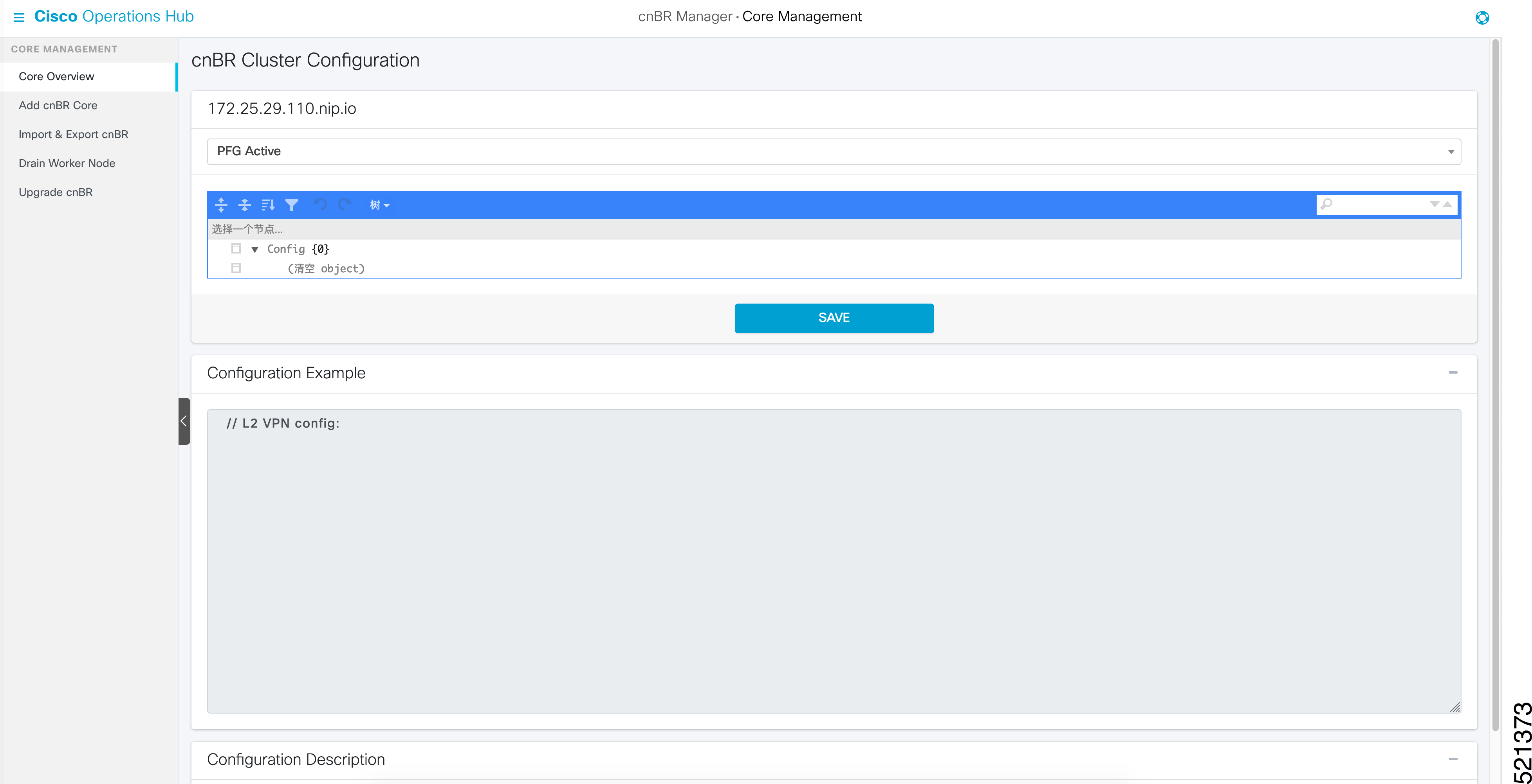
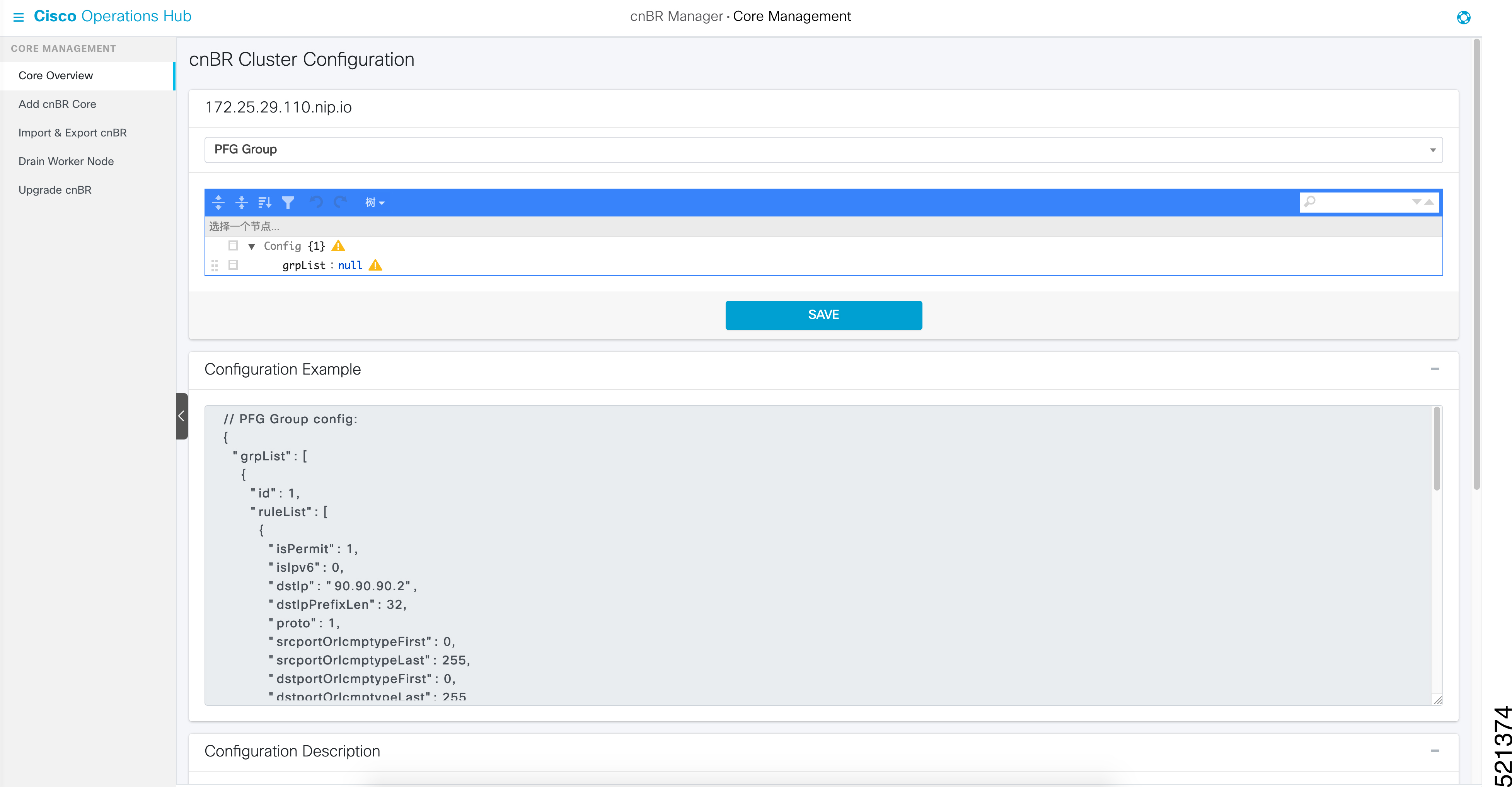
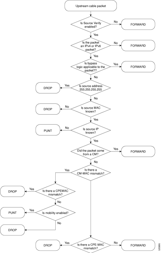
Cisco Cloud Native Broadband Router Service Configuration and Monitoring

Cisco cnBR virtualizes all hardware-based services, provides a cloud-native design, and offers a variety of features as microservices. You can quickly develop, test, and deploy new services or update features and functions without any downtime.

Network Services

Cisco cnBR empowers you to create a number of easily composable, scalable, and resilient network services.

DHCP Relay Service

Cisco cnBR acts as a Dynamic Host Configuration Protocol (DHCP) relay agent to implement features such as DHCP relay, Lease Query (LQ), IPv6 Prefix Delegation (PD), and to provision static IP addresses for subscribers by using source address verification (SAV).

DHCP Relay

When the Cisco cnBR acts as a relay agent, it forwards requests and replies between clients and servers when they are not on the same physical subnet. Relay agent forwarding is different from normal IP router forwarding. In normal IP router forwarding, IP datagrams are forwarded between networks transparently. However, in relay agent forwarding, relay agent receives a DHCP message and then generates a new DHCP message to send through another interface.

When a DHCP client requests an IP address from a DHCP server, for instance DHCPv4, the client sends a DHCPDISCOVER broadcast message to locate the DHCP server. Relay agent forwards the packets between the DHCP client and the DHCP server. The DHCP server provides configuration parameters, such as IP address, MAC address, domain name, and a lease for the IP address, to the client in a DHCPOFFER unicast message.

User Guidelines:

  • By default, DHCP relay is enabled on Cisco cnBR. DHCP relay depends on two Cisco cnBR services in the multiple instances environment - BGP agent and Relay proxy.

  • DHCP relay agent configuration is based on service group.

  • DHCP server receives DHCP request. If multiple DHCP servers are configured, all these servers receive relay packets.

  • The v4Net/v6Net defines all the IP scopes for the subscriber's DHCP destination IP address. This configuration must be consistent with the configuration of the DHCP server. If multiple subscriber nets are configured, use the first scope as the default scope.

  • Cisco cnBR can also assign a specific server or IP scope for a subscriber. For more information, see Policy Based Relay.

Policy Based Relay

Policy Based Relay allows subscribers with different device classes to be classified into different IP ranges.

When the relay agent handles subscriber DHCP packets, Cisco cnBR can identify its device class based on the TLV (Tag, Length, Value) in the DHCP packets. Then the Cisco cnBR uses a predefined relay policy to assign a specific server to get DHCP address, or notify the server to assign its DHCP address in a specific IP range.

User Guidelines:

  • Define the v4serverip/v6serverip in the dhcpServers.

  • Define the giaddr/linkaddr with associated v4Nets and/or v6Nets. The address is the prefix of the v4Nets/v6Nets.

  • If there is no specific v4serverip/v6serverip for the device class, the subscriber requests are forwarded to all the servers defined.

  • If there is no specific giaddr/linkaddr for the device class, the subscribers get the IP from the first default range.

DHCPv6 Prefix Delegation

In the IPv6 networking, you can use the DHCPv6 prefix delegation (PD) to assign network address prefix, automate configuration, and provision the public routable addresses for the network. For example, in home networks, home routers use the DHCPv6 protocol to request a network prefix from the ISP's DHCPv6 server. After you assign the network prefix, the ISP routes this network prefix to your home router. Then the home router starts displaying the new addresses to hosts on the network.

After the PD router comes online, it gets the assigned network prefix from the DHCP server.

ARP/NDP Glean and Lease Query

As a relay agent, Cisco cnBR stores all subscriber DHCP information after DHCP is completed. Based on this information, routing is established for subscribers. However, there are several cases when subscriber information is unavailable, such as a modem reset, resulting in routing being no longer available for subscribers. When these subscribers access the network, Cisco cnBR rebuilds the data path by using ARP/NDP glean or lease query.

When using ARP/NDP Glean, Cisco cnBR can trust the packets that come from the cable side network. After the ARP/NS is received and the source IP is updated in the configured IP ranges, Cisco cnBR rebuilds a data path for the source MAC. This method is open to MAC spoofing.

In contrast, when using Lease Query, Cisco cnBR doesn't trust the cable side network. When Cisco cnBR receives the upstream packet with no data path route, it sends a LEASEQUERY request to DHCP server. After DHCP server gets the request and confirms that the RESPONSE, the MAC and IP are released from DHCP server, Cisco cnBR rebuilds the data path. Otherwise, Cisco cnBR drops the packets.

User guidelines:

  • Enable or disable ARP/NDP Glean and Lease Query on demand.

  • Lease Query checks the source IP with the v4Nets/v6Nets configuration. If the source IP of the packets isn't in the range, then Lease Query discards the packet.

  • Use ARP/NDP Glean and Lease Query with Source Address Verification (SAV).

Source Address Verification (SAV)

In addition to DHCP leased IP address, Cisco cnBR allows static IP address by provisioning SAV group.

A SAV group is a group of IPv4 or IPv6 prefixes. Cisco cnBR uses these prefixes to authenticate a cable modem (CM). You can configure a CM with an IPv4 or IPv6 prefix that belongs to a particular SAV group. The time, length, and the value (TLV) 43.7.1 specify the group name to which a given CM belongs. If the source IP address of a packet from a CM belongs to the configured prefix in a SAV group, the Cisco CMTS considers it as an authorized packet.

You can configure a maximum of 255 SAV groups on a Cisco cnBR. Each SAV group contains up to four IPv4s, IPv6s, or a combination of both prefixes. The total number of the prefixes is not more than four.

During registration, CMs communicate their configured static prefixes to the CMTS using TLV 43.7.1 and TLV 43.7.2. The TLV 43.7.1 specifies the SAV prefix group name that the CM belongs to, and TLV 43.7.2 specifies the actual IPv4 or IPv6 prefix. Each CM can have a maximum of four prefixes configured. When the Cisco CMTS receives these TLVs, it identifies whether the specified SAV group and the prefixes are already configured on the Cisco CMTS. If these are configured, the Cisco CMTS associates them to the registering CM. However if these are not configured, the Cisco CMTS automatically creates the specified SAV group and prefixes before associating them to the registering CM.

The Cisco CMTS considers the SAV group name and the prefixes that are provided by these TLVs to be valid. The packets received from the CM, with the source IP address belonging to the prefix specified by the TLV, are authorized packets. For example, if a given CM has an SAV prefix of 10.10.10.0/24, and the source IP address of a packet received from this CM (or CPE behind the CM) is in the subnet 10.10.10.0/24, then it is an authorized packet.

User guidelines:

  • SAV configuration is global and not for each service group.

  • SAV doesn’t check the MAC/IP binding. You can assign the static IP to any MAC.

  • By default, SAV is disabled. You can enable it on demand.

ARP/NDP Proxy

All cable modems and subscribers are behind the HFC network. As a proxy, Cisco cnBR relays the ARP/NDP requests to the CM.

With ARP/NDP proxy enabled, Cisco cnBR can respond the ARP/NDP, and the DS lease query is not to be triggered.

Mobility Scopes

If the subscribers are allowed to roam between different IPv4 and IPv6 scopes, the mobility scopes contain all the IPv4 and IPv6 scopes granted to the subscribers. This configuration is optional.

Configure DHCP Relay Service

The DHCP relay service operates in a similar way as other Cisco CMTS products. You can configure it with Autodeployer Script, or by importing the whole Cisco cnBR configuration YAML file to the desired Cisco cnBR using Cisco Operations Hub. The imported configuration file overwrites the existing configuration and activates the new configuration.

Update the DHCP Relay configuration using Autodeployer reconfig (Preferred)

After configuring the DHCP Relay using the Autodeployer during deployment, you can modify the dhcp block in the L3 profile file and run the AutoDeployer configuration script again to update the configuration.


Note

Rerunning AutoDeployer configuration script causes all the RPDs/SGs to be deleted and added.


Update DHCP Relay Configuration Using cnBR Manager

After configuring the DHCP Relay using the Autodeployer during deployment, you can also update the configuration using the cnBR Manager UI.

Use the following steps to update the DHCP Relay configuration:

Procedure

Step 1

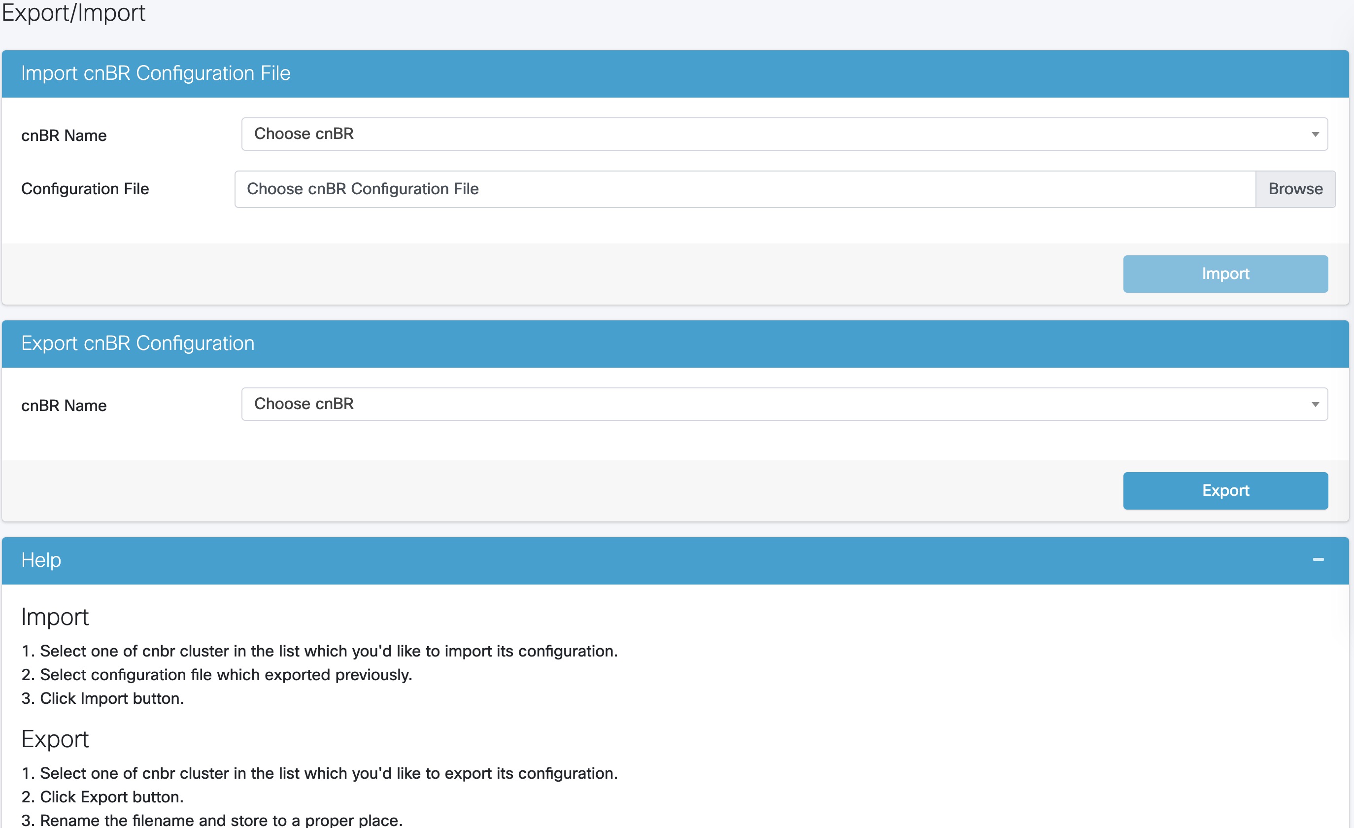
Click the Cisco Operations Hub main menu button on the top left corner, choose cnBR Manager > Core Management, and click Import & Export cnBR.

The Export/Import page opens.

Step 2

In the Export cnBR Configuration section, from the drop-down list, choose the required Cisco cnBR to update.

Step 3

Click Export to get the current SG configuration of the selected Cisco cnBR.

Step 4

In the .json file, update one or more parameters in the dhcp section of the SG configuration.

Step 5

Save the updated configuration file on the local disk.

Step 6

In the Import cnBR Configuration File pane, from the drop-down list, choose the Cisco cnBR to update.

Step 7

Click Browse to locate the file which you updated (saved at Step 5).

Step 8

Click Import to upload the updated SG configuration to the selected Cisco cnBR.


Configure DHCP Relay using Autodeployer Script

In the AutoDeployer script L3 profile file, the DHCP Relay configuration is saved in the dhcp section. It is applied to all Service Groups on the Cisco cnBR. The following is an example configuration:

"Dhcp":
    {
        "ArpGlean":true,
        "ArpProxy":true,
        "ipv4Lq": false,
        "NdGlean":true,
        "NdProxy":true,
        "ipv6Lq":false,
        "dhcpServers":["80.80.80.3",
                      "81.81.81.3",
                      "2001:80:80:80::3",
                      "2001:81:81:81::3"
        ],
        "V4Nets":["90.90.90.1/24",
                  "91.91.91.1/24",
                  "92.92.92.1/24"
        ],
        "V6Nets":["2001:90:90:90::1/64",
                  "2001:91:91:91::1/64",
                  "2001:92:92:92::1/64"
        ],
        "RelayPolicies":[
          {"deviceClass": "HOST",
          "v4serverip": "80.80.80.3",
          "v6serverip": "2001:80:80:80::3",
          "giaddr": "90.90.90.1",
          "linkaddr": "2001:90:90:90::1"
          },
          {"deviceClass": "STB",
          "v4serverip": "81.81.81.3",
          "v6serverip": "2001:81:81:81::3",
          "giaddr": "91.91.91.1",
          "linkaddr": "2001:91:91:91::1"
          },
          {"deviceClass": "PS",
          "giaddr": "92.92.92.1",
          "linkaddr": "2001:92:92:92::1"
          },
          {"deviceClass": "EROUTER",
          "v4serverip": "80.80.80.3",
          "v6serverip": "2001:80:80:80::3",
          },
          {"deviceClass": "DVA",
          "giaddr": "90.90.90.1",
          "linkaddr": "2001:90:90:90::1"
          },
          {"deviceClass": "MTA",
          "giaddr": "91.91.91.1",
          "linkaddr": "2001:91:91:91::1"
          }
        ],
        "mobilityScopes":["90.90.90.1/24",
                          "91.91.91.1/24",
                          "92.92.92.1/24",
                          "2001:90:90:90::1/64",
                          "2001:91:91:91::1/64",
                          "2001:92:92:92::1/64"
        ]
    }

See Configure Cisco cnBR Using Autodeployer for additional information.

Configure DHCP Relay
Field Name Description Type Enforcement
dhcpServers DHCP server IPv4 and IPv6 addresses IPv4 or IPv6 Required
v4Nets IPv4 range to which the subscriber's DHCP address belongs CIDR (Classless Inter-Domain Routing) Required
v6Nets IPv6 range to which the subscriber's DHCP address belongs CIDR (Classless Inter-Domain Routing) Required
    "Dhcp":
    {
        // all the DHCP servers IP, V4 and V6
        "dhcpServers":[
                        "81.81.81.3",
                        "24.24.24.3",
                        "2001:81:81:81::3",
                        "2001:24:24:24::3"
                      ],
        // all the V4 subnets for the subscribers in this SG
        "v4Nets":[
                    "90.90.90.1/24",
                    "91.91.91.1/24",
                    "92.92.92.1/24",
                    "93.93.93.1/24",
                    "94.94.94.1/24",
                    "95.95.95.1/24"
                    "96.96.96.1/24",
                    "97.97.97.1/24",
                ],
        // all the V6 subnets for the subscribers in this SG
        "v6Nets":[
                    "2001:90:90:90::1/64",
                    "2001:91:91:91::1/64",
                    "2001:92:92:92::1/64",
                    "2001:93:93:93::1/64",
                    "2001:94:94:94::1/64",
                    "2001:95:95:95::1/64",
                    "2001:96:96:96::1/64",
                    "2001:97:97:97::1/64"
                ],
    }
Configure DHCP Relay Policy
Field Name Description Type Enforcement
deviceClass The device class for each subscriber String Required
v4serverip The server to which the DHCP request is forwarded IPv4 Optional
v6serverip The server to which the DHCPv6 request is forwarded IPv6 Optional
giaddr The IP range to which the DHCPv4 address belongs; the giaddr is the IP address in the v4Nets IPv4 Optional
linkaddr The IP range to which the DHCPv6 address belongs; the linkaddr is the IP address in the v6Nets IPv6 Optional
    "Dhcp":
    {
	    "RelayPolicies":[
			{"deviceClass": "HOST",
			 "giaddr": "92.92.92.1",
			 "v4serverip": "24.24.24.3",
			 "linkaddr": "2001:92:92:92::1"
			},
			{"deviceClass": "STB",
			 "giaddr": "93.93.93.1",
			 "v4serverip": "81.81.81.3",
			 "linkaddr": "2001:93:93:93::1"
			},
			{"deviceClass": "PS",
			 "giaddr": "94.94.94.1",
			 "v6serverip": "2001:81:81:81::3",
			 "linkaddr": "2001:94:94:94::1"
			},
			{"deviceClass": "EROUTER",
			 "giaddr": "95.95.95.1",
			 "linkaddr": "2001:95:95:95::1"
			},
			{"deviceClass": "DVA",
			 "giaddr": "96.96.96.1",
			 "v4serverip": "24.24.24.3",
			 "linkaddr": "2001:96:96:96::1"
			},
			{"deviceClass": "MTA",
			 "giaddr": "97.97.97.1",
			 "v6serverip": "2001:24:24:24::3",
			 "linkaddr": "2001:97:97:97::1"
			}]
    }
Configure ARP/NDP Glean and Lease Query
Field Name Description Type Enforcement
arpGlean Enable/Disable Boolean Required; default is false
ndGlean Enable/Disable Boolean Required; default is false
ipv4Lq Enable/Disable Boolean Required; default is false
ipv6Lq Enable/Disable Boolean Required; default is false
    "Dhcp":
    {
        "arpGlean":true,
        "ipv4Lq": false,
        "ndGlean":false,
        "ipv6Lq": false,
    }
Configure SAV
Field Name Description Type Enforcement
savEnable Enable/Disable Boolean Required
savEntires SAV group structure savGroup Optional
grpName SAV group name String Optional
prefixes The SAV prefixes CIDR (Classless Inter-Domain Routing) list Optional
    "sav"
    {
        "savEnable": true,
        "savEntries": [{
                        "grpName": "testSAVV",
                        "prefixes": ["93.93.93.100/28",
                                     "2001:93:93:93100::0/72"]

                      }]
    }   
Configure ARP/NDP Proxy
Field Name Description Type Enforcement
ArpProxy Enable/Disable Boolean Required; default false
NdProxy Enable/Disable Boolean Required; default false
    "ArpProxy":true,
    "NdProxy":true,
Configure Mobility Scopes
Field Name Description Type Enforcement
mobilityScopes Scopes of ipv4 and ipv6 String Optional
  "mobilityScopes":["90.90.90.1/24",
                    "91.91.91.1/24",
                    "92.92.92.1/24",
                    "2001:90:90:90::1/64",
                    "2001:91:91:91::1/64",
                    "2001:92:92:92::1/64"
                   ]

Monitor DHCP Relay Service

DHCP IPv4 Statistics
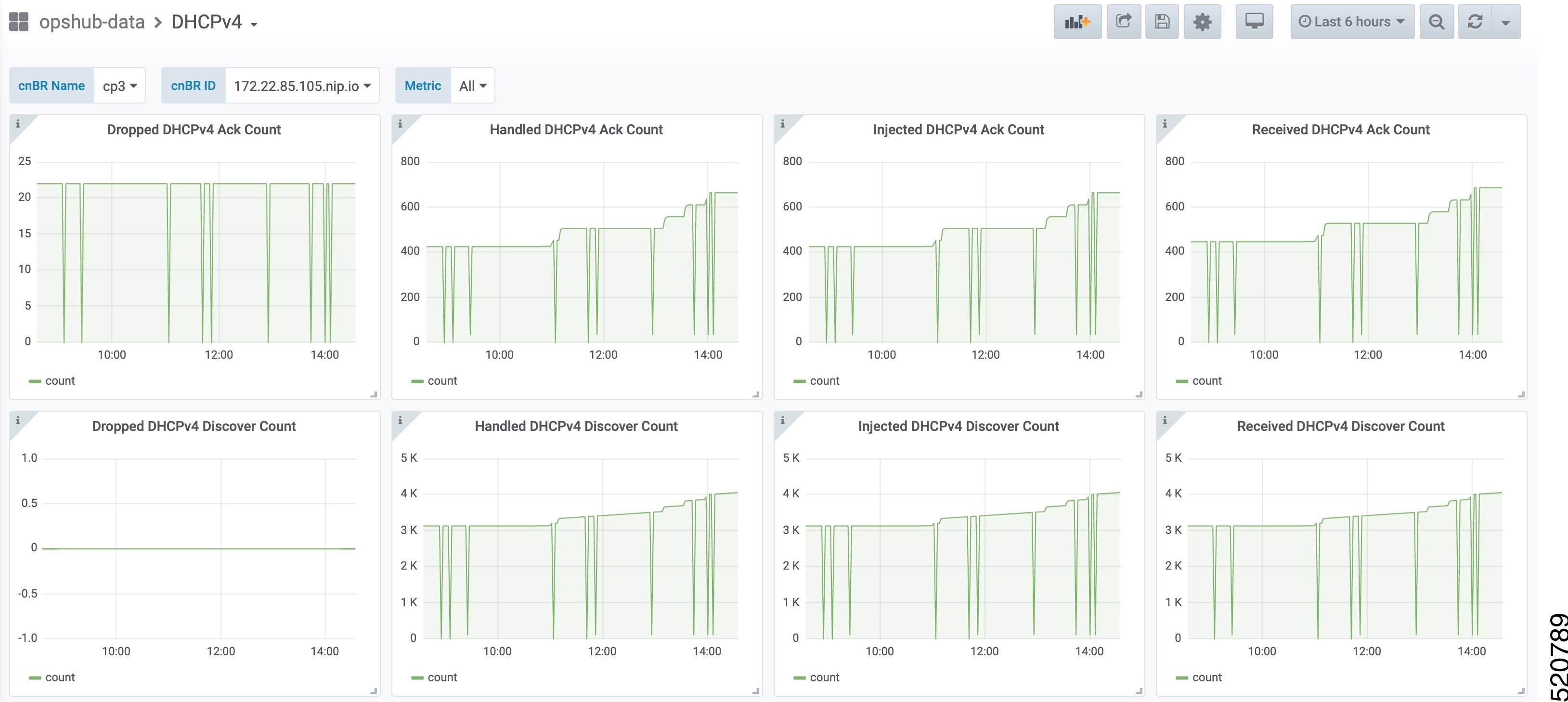
Figure 1. DHCPv4 panel in cnBR Manager Metrics

This dashboard panel (DHCPv4) in cnBR Manager Metrics is displaying statistics of the DHCP relay of IPv4. In all, there are 16 dashboards. The preceding picture shows only half the number of dashboards. Each dashboard represents the count of different states for different packet over time. There are four packet types for DHCPv4: Discover, Offer, Request, and Acknowledgment (Ack). The system processes each type of packet differently: Received, Dropped, Handled, and Injected. You can change the time span at the top-right corner. Currently, they show the count for the last six hours.

DHCP IPv6 Statistics
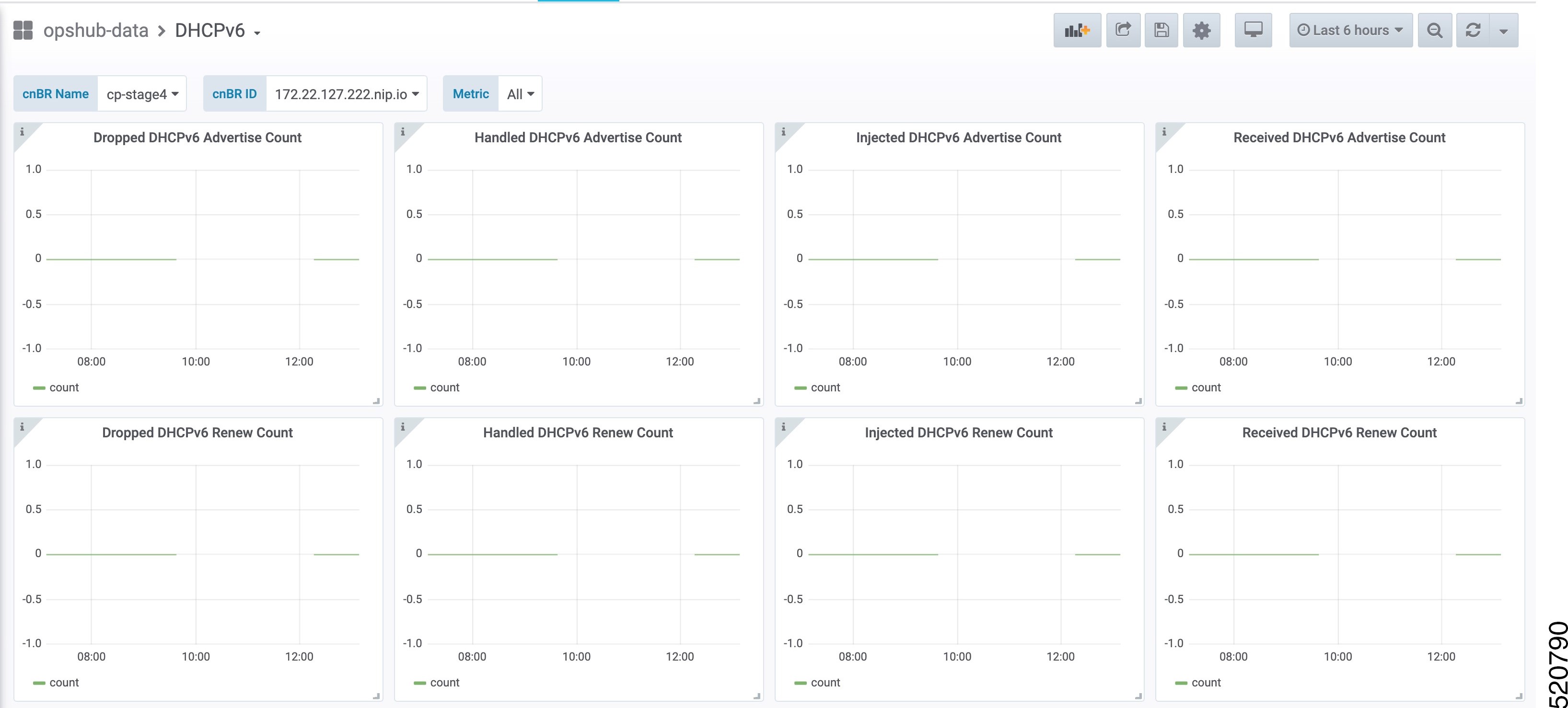
Figure 2. Screenshot of DHCPv6 panel in cnBR Manager Metrics

This dashboard panel (DHCPv6) in cnBR Manager Metrics displays statistics of the DHCP relay of IPv6. In all, there are 16 dashboards. The preceding picture shows only half the number of dashboards. Each dashboard represents the count of different states for different packet over time. There are four packet types for DHCPv4: Renew, Advertise, Request, and Reply. The system processes each type of packet differently: Received, Dropped, Handled, and Injected. You can change the time span at the top-right corner. Currently, they show the count for the last six hours.

PTP

Precision Time Protocol (PTP) is used to synchronize clocks throughout all cable networks. The Cisco cnBR cores and RPDs are managed by the Cisco cnBR, and runs an instance of the PTP client. To achieve time synchronization, the PTP client in Cisco cnBR and the PTP client in RPDs must synchronize their clocks to the same PTP primary clock. The Cable Modems (CMs) then synchronize their clock to the Cisco cnBR (and eventually to the PTP primary clock) through the DOCSIS timestamps provided by the RPD.

PTP allows creation of individual profiles for different scenarios. A profile is a specific selection of PTP configuration options that are selected to meet the requirements of a particular application. Cisco cnBR supports the PTP default profile.

To provide a high availability precision clock in the Cisco cnBR, two PTP primary clock sources can be configured in cnBR - a main PTP primary clock server and an alternate PTP primary clock server. Cisco cnBR synchronizes its clock to the best available PTP primary clock.

Some of the key parameters that are configured, or configurable, in the Cisco cnBR and RPD PTP client include:

  • PTP Domain

    A PTP domain is a logical grouping of clocks that communicate with each other using the PTP protocol. A single computer network can have multiple PTP domains operating separately. For example, one set of clocks synchronized to one time scale and another set of clocks synchronized to another time scale. PTP can run over either Ethernet or IP, so a domain can correspond to a Local Area Network, or it can extend across a Wide Area Network.

    In Cisco cnBR and RPD PTP client, the PTP domain is set during initial Cisco cnBR deployment. The PTP domain can be updated after deployment.

  • PTP Transport

    In Cisco cnBR and RPD, the PTP transport is configured to use PTP over IPv4 in unicast mode. The PTP Transport mode is not configurable in Cisco cnBR PTP client. The PTP Transport mode is configurable in the RPD PTP client.

  • PTP Ports

    A port can be configured to perform either fixed primary or secondary role, or can be configured to change its role dynamically. If no role is assigned to a port, it can dynamically assume a primary, passive, or secondary role, based on the Best Master Clock Algorithm (BMCA).

    Cisco cnBR and RPD support the PTP port secondary role. The Cisco cnBR PTP port role is not configurable. However, the RPD PTP port role is configurable, but it must be set to secondary role.

  • PTP Clock Mode

    PTP Clock Mode can be configured as either of the following modes:

    • 1-step clock mode: The PTP primary clock includes its timestamp in the synchronization message when the synchronization message is sent by the hardware. This mode requires hardware to insert the clock timestamp right before the synchronization message is sent through the wire.

    • 2-step clock mode: The PTP primary clock sends its timestamp in a separate message after sending the synchronization message. This mode does not require hardware support, but the timestamp messages and the synchronization messages may arrive at the PTP clients out of order in some scenarios.

    Cisco cnBR and RPD support the 1-step clock mode. The PTP Clock mode is not configurable.

Configure PTP

The PTP client in Cisco cnBR and RPD can be configured during the initial Cisco cnBR configuration using Autodeployer.

Procedure

Step 1

The top-level Autodeployer configuration file used in the deployment of Cisco cnBR must include the configuration for the PTP client in the Cisco cnBR.

Table 1.

Field Name

Description

Mandatory

ptp:v4:

PTP IPv4 related parameters for the Cisco cnBR PTP container

Yes

domain

Clock domain of the PTP primary server

Yes

master:ip

IPv4 address of the PTP clock primary server

Yes

master:gw

IPv4 address of the Gateway to access the PTP clock primary server

Yes

alt-master:ip

IPv4 address of the PTP alternate clock primary server

No

alt-master:gw

IPv4 address of the gateway to access the PTP alternate clock primary server

No

dscp

Differentiated Services Codepoint. Default: 46

No

SG_template

Go through the SG template listed in step Step 2

Yes

Step 2

The reference Service Group template should include the configuration of the PTP client in the RPD. Go through the following table for the detailed values.

Table 2.

Field Name

Description

Mandatory

rpdPtpCfg:

< PTP related parameters for the PTP client in the RPD >

Yes

domain

Clock domain of the PTP primary server

Yes

dtiMode

DOCSIS Time Interface Mode

Yes

priority1

Priority1

No

priority2

Priority2

No

ptpClkProfileId

PTP clock profile ID in PTP primary server

Yes

ptpPortCfg: adminState

PTP port adminstration state

Yes

ptpPortCfg: anncReceiptTimeout

Annoucement Receipt Timeout interval

No

ptpPortCfg: cos

COS of 802.1Q

No

ptpPortCfg: dscp

DSCP of IP Differentiated Services

No

ptpPortCfg: enetPortIndex

Ethernet port index for the clock port

No

ptpPortCfg: gateway

IPv4 address of the gateway to access the PTP primary clock server

Yes

ptpPortCfg: gatewayAlt

IPv4 address of the Alt gateway to access the PTP primary clock server

No

ptpPortCfg: masterAddr

IPv4 address of the PTP primary clock server

Yes

ptpPortCfg: masterAddrAlt

IPv4 address of the Alt PTP primary clock server

No

ptpPortCfg: localPriority

Local Priority

No

ptpPortCfg: logDelayReqInterval

Interval for PTP delay-req packets0-7(-7 -0)

Yes

ptpPortCfg: logSyncInterval

Interval for Sync packets

Yes

ptpPortCfg: masterAdminState

PTP Primary Administration State

Yes

ptpPortCfg: ptpPortIndex

PTP Port Index

Yes

ptpPortCfg: unicastDuration

The grant duration time in seconds for unicast

No

For more information on the listed parameters, go through the RPD documentation at https://www.cisco.com/c/en/us/td/docs/cable/cbr/configuration/guide/b-rpd-full-book-11/b-rpd-full-book-11_chapter_011.pdf.


Example
  • Cisco cnBR PTP client-related parameters in Autodeployer top-level configuration file:
    // IPv4 address of PTP Master Clock and alternate Master clock servers,
    // and their respective Gateway server, in the top level config file.
    ptp :
        v4 :
           domain : 0
           master: {'ip':"100.158.158.158", 'gw':"10.70.78.1"}
           alt-master: {'ip':"100.158.158.159", 'gw':"10.70.78.1"}
    
    // Specify the "SG template" that contains the RPD PTP CLient parameters.
        SG : 
            'SG_4x4': 'sg_template.json'
  • RPD PTP client-related parameters in the SG_template:
    "rpdPtpCfg": {
        "dtiMode": "SlaveDtiMode",
        "domain": 44,
        "priority1": 128,
        "priority2": 255,
        "ptpClkProfileId": "00:00:00:00:00:00",
        "ptpPortCfg": [
          {
            "adminState": "Up",
            "anncReceiptTimeout": 11,
            "cos": 6,
            "dscp": 47,
            "enetPortIndex": 1,
            "gateway": "10.70.78.1",
            "gatewayAlt": "10.70.78.xxx",
            "localPriority": 128,
            "logDelayReqInterval": -4,
            "logSyncInterval": -4,
            "masterAddr": "100.158.158.158",
            "masterAddrAlt": "100.158.158.xxx",
            "masterAdminState": "Up",
            "ptpPortIndex": 22,
            "unicastDuration": 300
          }
        ]
      }

Update cnBR PTP Configuration using Autodeployer

You can update the Cisco cnBR PTP configuration using the Autodeployer.

Ensure that you have configured the Cisco cnBR PTP client during deployment, and the Cisco cnBR using the Autodeployer.

See Configure Cisco cnBR Using Autodeployer for more information.

Go through the following steps to update the PTP configuration:

Procedure

Step 1

Locate the Autodeplyer configuration files used for the initial deployment and configuration of cnBR. This includes:

  • Top-level Autodeployer configuration file

  • SG template

  • L3 template

Step 2

Update the PTP section of the top-level Autodeployer configuration file.

Step 3

Run the Autodeployer configuration script.

Note 

All RPDs or SGs (including unchanged SGs), are first deleted and added when you rerun the Autodeployer configuration.


Update cnBR PTP Configuration using cnBR Manager

You can update the Cisco cnBR PTP configuration using the cnBR Manager.

Ensure that you have configured the Cisco cnBR PTP client during deployment and the Cisco cnBR using the Autodeployer. Also, ensure that the Cisco cnBR is added to the cnBR Manager.

To view and update the PTP configuration parameters, use the following procedure:

Procedure

Step 1

Click the Cisco Operations Hub main menu button on the top left corner, choose cnBR Manager > Core Management, and click Core Overview.

Step 2

Choose a Cisco cnBR core from the list.

Step 3

Choose PTP from the drop-down list and edit the configuration using one of the following modes:

  • Tree mode: Select Tree mode to edit each field.

  • Code mode: Select Code mode to edit the configuration in plain text.

Step 4

Configure the Cisco cnBR PTP client with either a single primary clock or with dual primary clocks.

The following image shows the Cisco cnBR PTP client with a single primary clock.
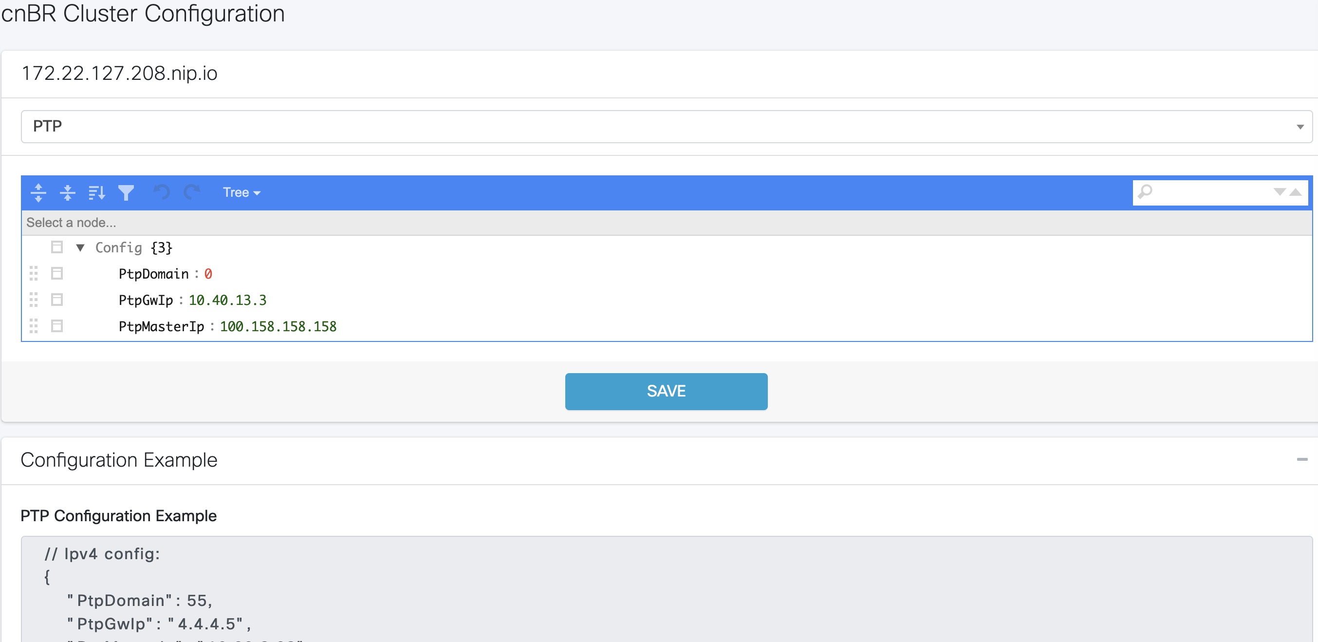
Figure 3. Configuring cnBR PTP Client with a Single Primary Clock


The following image shows the Cisco cnBR PTP client with dual primary clock.
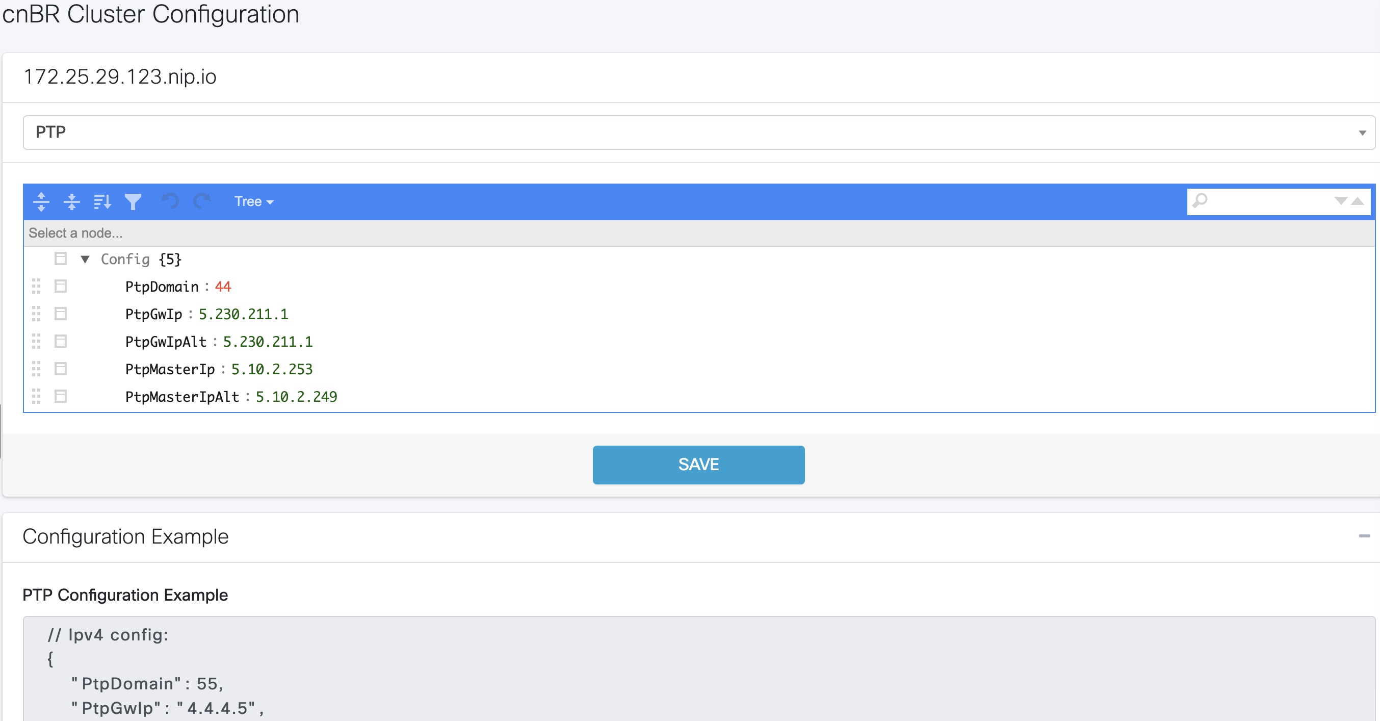
Figure 4. Configuring cnBR PTP Client with a Dual Primary Clock


Update RPD PTP Configuration using Autodeployer

You can update the RPD PTP configuration using the Autodeployer. We recommend this method of updating the RPD PTP.

Ensure that you have configured the RPD PTP client during the deployment, and have configured Cisco cnBR using the Autodeployer.

See Configure Cisco cnBR Using Autodeployer for more information.

Procedure

Step 1

Locate the complete set of Autodeplyer configuration files used in the initial deployment and configuration of cnBR. This includes:

  • Top-level Autodeployer configuration file

  • SG template

  • L3 template

Step 2

Update the rpdPtpCfg section of the Service Group template.

Step 3

Run the Autodeployer configuration script.

Note 

Rerunning the Autodeployer configuration causes all the RPDs or SGs, including unchanged SGs, to be first deleted and added.


Update RPD PTP Configuration using cnBR Manager

You can update the RPD PTP configuration using the cnBR Manager.

Ensure that you have configured the RPD PTP client during deployment, and have configured Cisco cnBR using the Autodeployer.

To view and update the RPD PTP configuration parameters, use the following procedure:

Procedure

Step 1

Click the Cisco Operations Hub main menu button on the top left corner, choose cnBR Manager > Core Management, and click Import & Export cnBR.

The Export/Import page opens.

Step 2

On the Export cnBR Configuration pane, choose the Cisco cnBR that you want to update.

Step 3

Click Export to retrieve the current SG configuration of the selected Cisco cnBR.

Step 4

In the <filename>-configuration.txt file, update the parameters in the rpdPtpCfg section of the SG configuration.

Step 5

Save the updated file to the local disk.

Step 6

Update the SG configuration.

  1. In the Import cnBR Configuration File pane, choose the file that you updated.

  2. Click Import to update the SG configuration to the RPD.

Step 7

Delete the RPD and add the RPD again for the updated SG configuration to take effect.


Monitor and Troubleshoot PTP

You can view the PTP status and its details on the PTP panel of the Metrics & Dashboards dashboard.

To view the Metrics & Dashboards dashboard, use the following procedure:

Procedure

Step 1

Enter the Cisco Operations Hub URL https://{Hostname} in the web browser.

Step 2

Click the Cisco Operations Hub main menu button on the top left corner, choose cnBR Manager > Metrics & Dashboard, and click Manage.

Step 3

Enter PTP in the search box and click the PTP row.

The PTP dashboard appears.
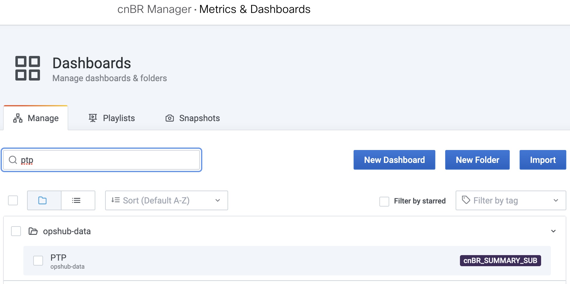
Figure 5. PTP Dashboard


Note 

The OffsetFromMaster must be within [-1ms, 1ms].


BGP Agent

The BGP Agent is a service in Cisco cnBR. It sets up BGP sessions with the SP router and installs or withdraws subscribed routes on the SP router while the subscribed devices (e.g. CM/CPE) are online.

The Cisco cnBR BGP Agent supports BGP version 4, includes address family IPv4 unicast, address family IPv6 unicast, and supports Graceful Restart.

Configure BGP Agent

You can perform the BGP Agent initial configurations through the Autodeployer Config file. See Configure Cisco cnBR Using Autodeployer for additional information.

After the initial setup, you can access BGP Agent configuration through the cnBR Manager. See instructions for Access BGP Agent Configuration.
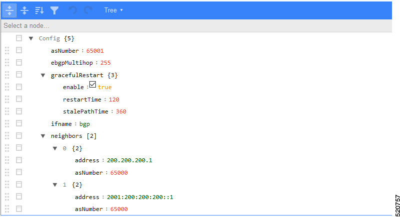
Configuration Parameters
Field Name Description Type Enforcement
asNumber BGP supports 2-byte AS numbers 1 ~ 65535 Required
ebgpMultihop The maximum number of eBGP hops allowed 0 ~ 255 Required
ifname BGP Agent interface name String, length 1 ~ 255 Required
neighbors BGP peer; BGP uses TCP port 179 to create a TCP session with a peer Required
weight Weight of BGP peers; if you configure two BGP IPv4/IPv6 peers, the upstream routes sent from these peers are accepted in the order of weight. Default: 100 Unsigned integer Optional
address BGP peer IP/IPv6 address String Required
gateway The gateway IP address if the BGP messages are transmitted to loopback interface on the SP router String Optional
gracefulRestart BGP graceful restart parameters Required
enable True, to enable the graceful restart BGP option and False, to disable it Bool Required
restartTime Determines how long the peer routers wait to delete stale routes before a BGP open message is received 1 ~ 3600 seconds Required
stalePathTime Determines how long a router waits before deleting stale routes after receiving an end of record (EOR) message from the restarting router 1 ~ 3600 seconds Required
Graceful Restart

When a BGP router restarts, all its neighbors detect that the BGP router went down and has come up again. It results in the deletion and adding back of the BGP routes in the neighbors. The unnecessary recomputation of routes, called a "routing flap", causes issues on both the BGP and neighbor routers. Graceful Restart allows the system to preserve the routes during BGP restart, thus minimizing the negative effects of BGP restart.

BGP Agent Configuration

The Cisco cnBR BGP Agent allows easy modification of BGP Agent global configurations.

Access BGP Agent Configuration
Procedure

Step 1

Log in to Cisco Operations Hub.

Step 2

Click the Cisco Operations Hub main menu button on the top-left corner, choose cnBR Manager > Core Management, and click Core Overview.

Step 3

Choose the required Cisco cnBR core from the list.

Step 4

Choose BGP Agent from the drop-down list.

The BGP Agent configuration details appear.

Add BGP Neighbors
Procedure

Step 1

In the BGP Agent configurator, expand neighbors field, and click the edit box of the last element.

Step 2

From the drop-down list, expand Append and select Object.
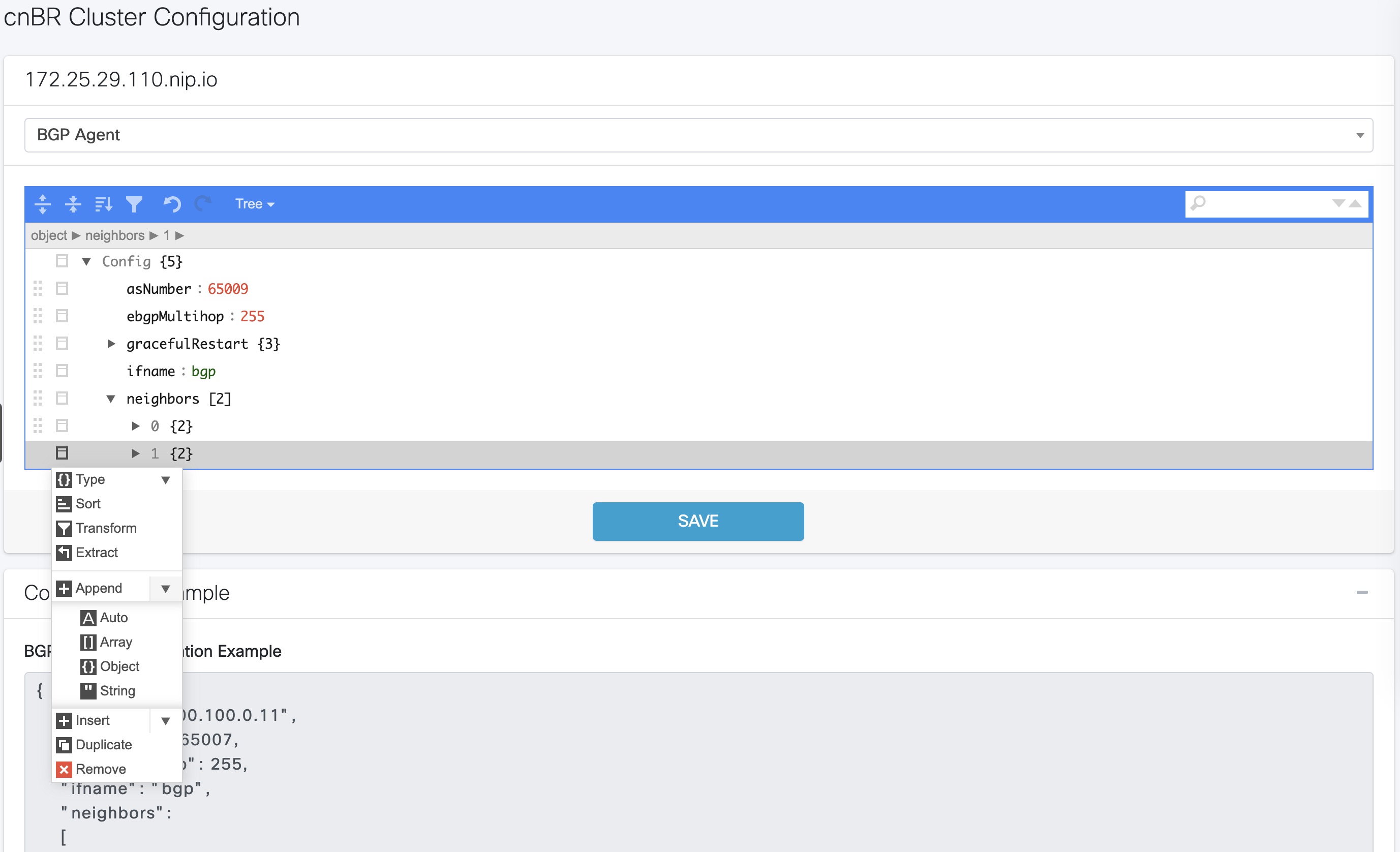
Step 3

In the new object, click the edit box of the (empty object) field.

Step 4

Choose Append from the drop-down list to create an object with two fields.
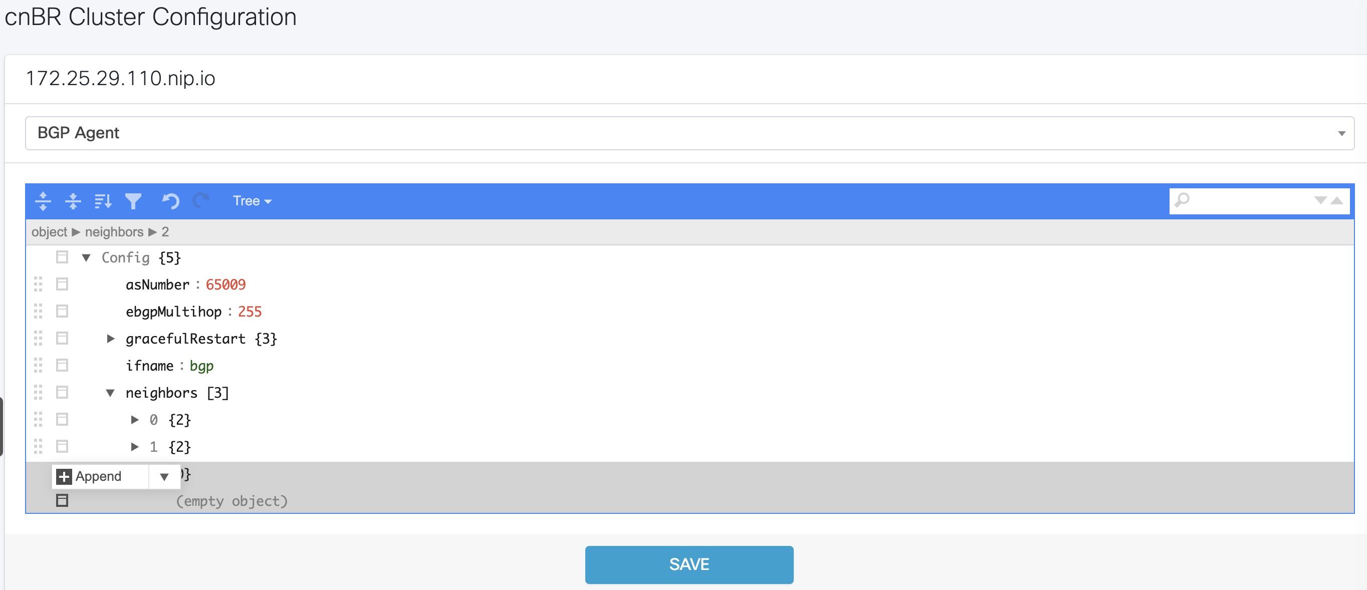
Step 5

In the first field, enter address, and in the second field, enter the IP address of the new neighbor.

Step 6

Click the edit box of the Address field and choose Append from the drop-down list to create an object with two fields.

Step 7

In the first field, enter asNumber and in the second field, enter the AS number of the new neighbor.

Step 8

Click Save.


Delete BGP Neighbors
Procedure

Step 1

In the BGP Agent configuration, expand all neighbor objects to locate the neighbor to delete.

Step 2

Select the edit box of the neighbor object to delete, then select Remove.

Step 3

Click Save.


Get BGP Neighbors

BGP neighbor information is stored in the neighbors field in the BGP configurator.
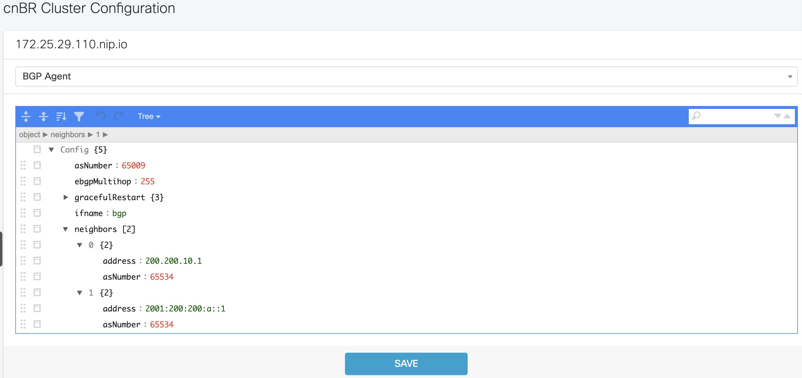
BGP Agent Dashboard

The Cisco cnBR BGP Agent Dashboard provides visibility into the BGP IPv4 and IPv6 routes and operation.

Access BGP Agent Dashboard
Procedure

Step 1

Log in to the Cisco Operations Hub.

Step 2

Click the Cisco Operations Hub main menu button on the top left corner, choose cnBR Manager > Metrics & Dashboard, and click Manage.

Step 3

Enter bgp in the search box and click the BGP Agent row.

Step 4

Choose the desired Cisco cnBR from the cnBR Name drop-down list.

The BGP Agent Dashboard of the desired Cisco cnBR appears.
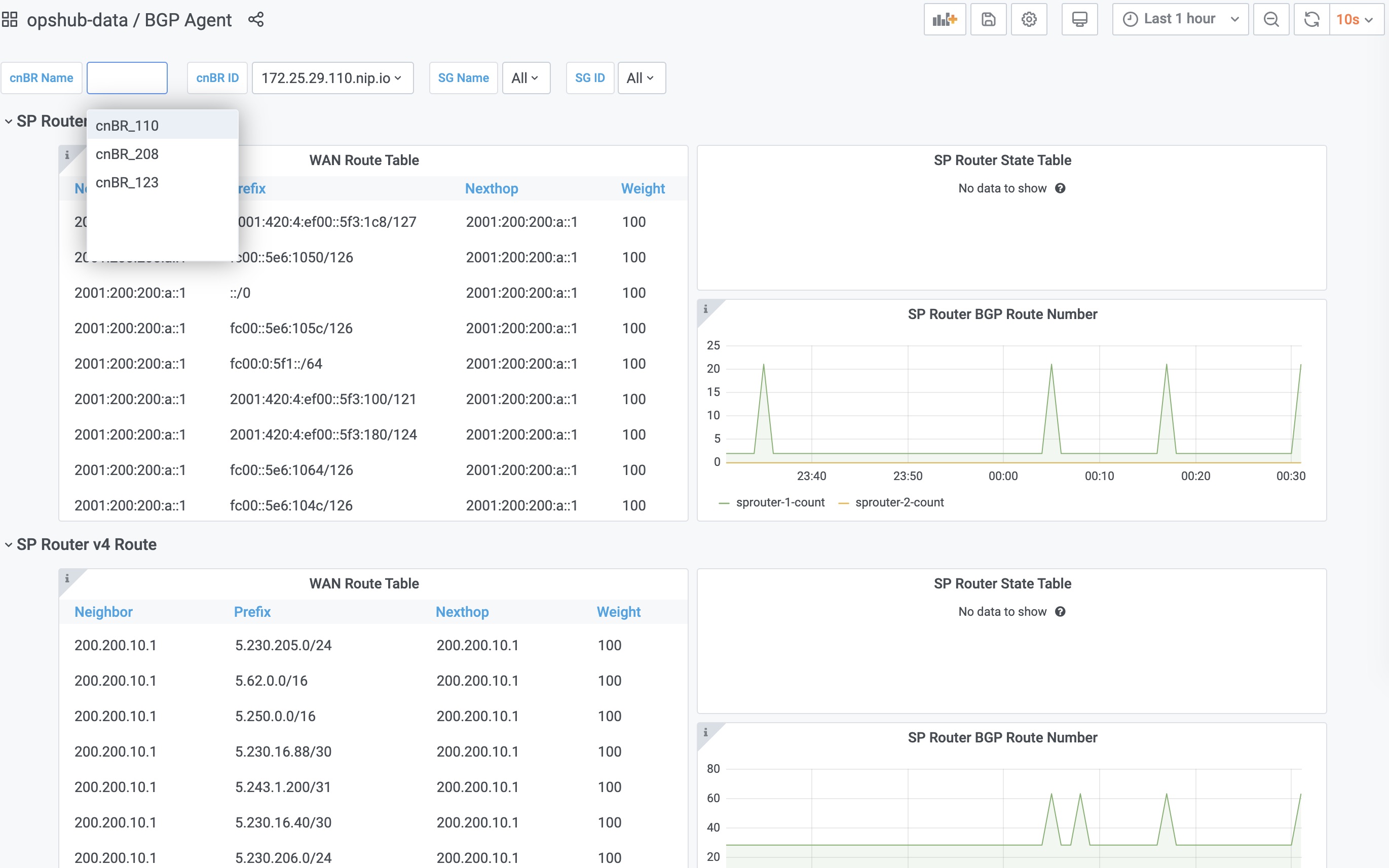

WAN Route Table

WAN Route Table displays the default routes generated by BGP Agent, and BGP routes received by the SP Router.

Table 3. Parameters
Name Description
Neighbor Neighbor IP address
Prefix Network segment of route
Nexthop IP address of next hop to get to destination
Weight Weight parameter described in Configuration Parameters
SP Router State Table

SP Router State Table displays the connection state between the BGP Agent and the SP router. The UP state indicates that the connection is established, and the DOWN state indicates the connection is not established.

Table 4. Parameters
Name Description
SP Router The IP address of the SP Router
State State of the connection between BGP Agent and SP Router
BGP Route Table

BGP Route Table displays the BGP routes that is sent to the SP router to route packets from CM to the correct DP.
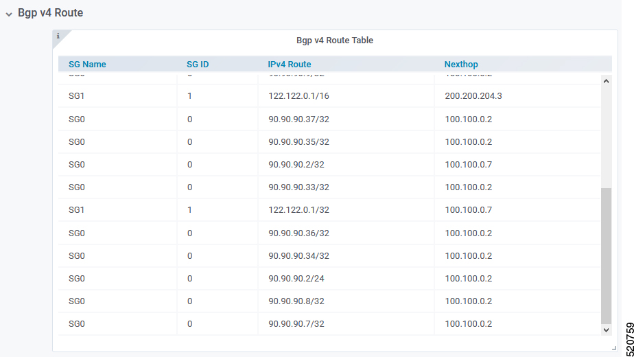
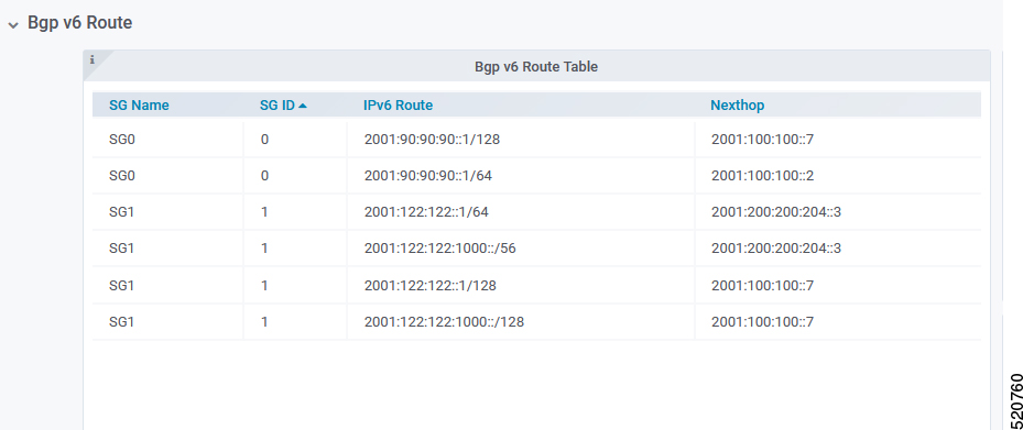
Table 5. Parameters
Name Description
SG Name Service Group name corresponding to the route
SG ID Service Group ID corresponding to the route
IP Route Destination IP address
NextHop Next IP address hop to get to destination
BGP Route Number

BGP Route Number displays the number of BGP routes installed into the SP router over time.

  • X-axis: Time

  • Y-axis: Number of BGP routes

BGP Route Rate

BGP Route Rate displays the rate of change of BGP routes over time.

  • X-axis: Time

  • Y-axis: Change rate of BGP routes

L2VPN

The Cisco cnBR application emulates the Layer 2 virtual private network (L2VPN), when L2VPN devices across shared or public networks appear as computing devices that are directly connected to a switch device. Therefore, Layer 2 packets from one device can reach the other device without changes to the Layer 2 packet header, similar to the traditional Layer 2 Forwarding method.

Several tunneling protocols are used to implement L2VPN. Cisco cnBR supports the point-to-point mode L2VPN for the IEEE 802.1Q (dot1q) protocol.

For the dot1q L2VPN, Cisco cnBR adds one layer dot1q tag for the upstream packet and removes the tag at the receiving end.

Cisco cnBR supports both cable modem (CM) based L2VPN and service flow (SF) based L2VPN.

  • CM-based L2VPN: One CM can configure one L2VPN service. Primary upstream and primary downstream packets are encapsulated into a L2VPN tunnel.

  • Service flow-based L2VPN: One CM can configure up to four L2VPN services using the CM configure file TLV. A maximum of eight upstream SFs and eight downstream SFs are supported for each L2VPN service. The upstream classifier on the CM and downstream classifier on the Cisco cnBR router are used to classify different packets into L2VPN service flows.

Cisco cnBR supports the following types of L2VPN tunnel:

Tunnel Type

CM-based

SF-based

dot1q

  • dot1q tunnel

  • Configure by Rest API

  • One L2VPN per CM

  • dot1q tunnel

  • Configured by CM configuration file TLV

  • Up to 4 L2VPN per CM

Configure L2VPN

The dot1q L2VPN is implemented using the Cisco cnBR router with a Service Provider (SP) router.

SP routers are Cisco ASR 9000, Cisco ASR 1000, or Cisco Network Convergence System 5501.

The connection between the Cisco cnBR router and the SP router is supported by either the VxLAN mode or the VLAN mode.

VxLan Mode

The following image shows the dot1q L2VPN packet flow from CPE to the dot1q tunnel.
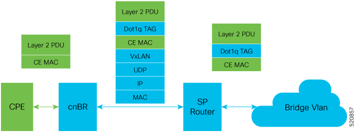
The following table summarizes the configuration that is required for the supported L2VPN types:

Tunnel Type

CM-based

SF-based

dot1q

  • Cisco cnBR configuration: static dot1q L2VPN

  • Cisco cnBR configuration: dot1q VxLAN wiring

  • SP router configuration: dot1q VxLAN wiring

  • CM configure file: dot1q L2VPN related TLV

  • Cisco cnBR configuration: dot1q VxLAN wiring

  • SP router configuration: dot1q VxLAN wiring

VLAN Mode

The following image shows the dot1q L2VPN packet flow from CPE to the dot1q tunnel.

The following table summarizes the configuration that is required for the supported L2VPN types:

Tunnel Type

CM-based

SF-based

dot1q

  • Cisco cnBR configuration: static dot1q L2VPN

  • Cisco cnBR configuration: dot1q VxLan wiring

  • SP router configuration: dot1q VxLan wiring

  • CM configure file: dot1q L2VPN related TLV

  • Cisco cnBR configuration: dot1q VxLan wiring

  • SP router configuration: dot1q VxLan wiring

Cisco cnBR L2VPN Configuration

For both CM-based and SF-based L2VPN, configure the L2VPN related VLAN or VxLAN that connects to the SP router. Use the cnBR Cluster Configuration window to configure the wiring.

For CM-based L2VPN, configure the static L2VPN map by using the REST API.

Procedure

Step 1

Click the Cisco Operations Hub main menu button on the top-left corner, choose cnBR Manager > Core Management, and click Core Overview.

Step 2

Choose the required Cisco cnBR core from the list.

Step 3

Select Wiring from the drop-down list.

Step 4

Update the configuration as required and click SAVE.


Static Dot1q L2VPN

To configure a cable modem (CM) as dot1q CM-based L2VPN, upstream traffic (primary service flow) adds one-level dot1q tag. Each L2VPN must have a different VLanId.

Procedure

Step 1

Click the Cisco Operations Hub main menu button on the top-left corner, choose cnBR Manager > Core Management, and click Core Overview.

Step 2

Choose the required Cisco cnBR core from the list.

Step 3

Choose Layer 2 VPN from the drop-down list.

Step 4

Update the configuration as required and click SAVE.


CM Configuration File TLV Definition

SF-based L2VPN depends on the CM configuration file TLV to set up L2VPN service, L2VPN service flow, and L2VPN classifier. For more details, see the CableLabs document: Business Services over DOCSIS Layer 2 Virtual Private Networks.

IPv6

Feature Name

Release

Feature Description

IPv6 WAN Protocols

Cisco cnBR 21.1

Allows you to use WAN protocols over IPv6. The WAN protocols consist of IPv6 BGP Agent, IPv6 DHCP Relay Agent and Proxy, and IPv6 DMIC.

Cisco cnBR supports IPv6 protocol when communicating with the following network devices:

  • Cable Modem (CM)

  • Customer Premise Equipment (CPE)-Equipment that is connected to the CM at the customer premise.


Note

Cisco cnBR supports dual-stack IPv4 and IPv6 protocols (It supports both IPv4 and IPv6 addresses at the same time).


Cisco cnBR supports WAN protocols over IPv6, along with CIN protocols. The WAN protocols consist of IPv6 BGP Agent, IPv6 DHCP Relay Agent and Proxy, and IPv6 DMIC. In the current network topology, both CIN and WAN networks are connected to the SP router through a layer 2 switch.

Configure IPv6 WAN

Configure Service Provider router BGP WAN, which includes BGP routing display, Wiring configuration, layer 3 (L3) configuration, SG template configuration, and DMIC configuration.

Following are a few sample configurations, which may be different for each vendor router. The current topology must have a Layer 2 switch between the SP router and Cisco cnBR.

Configure BGP WAN
```
interface Bundle-Ether1.1001
 description WAN-for-cnbr-mn   
 mtu 9216
 ipv4 address 200.200.9.1 255.255.255.0
 ipv4 address 100.100.9.1 255.255.255.0 secondary
 ipv6 address 2001:100:100::9:1/112
 ipv6 address 2001:200:200::9:1/112
 encapsulation dot1q 1001
!
router bgp 65534
 bgp router-id <rtr-id>
 address-family ipv6 unicast
  aggregate-address fd26:ba99:aae:944::/64 summary-only
  aggregate-address fd26:ba99:aae:2244::/96 summary-only
  aggregate-address fd26:ba99:aae:2344::/96 summary-only
  aggregate-address fd26:ba99:aae:2444::/64 summary-only
  redistribute connected
  redistribute static
 !
 neighbor-group ibgp
  remote-as 65534
  update-source Loopback0
  address-family ipv6 unicast
   route-policy pass-all in
   route-policy pass-all out
  !
 neighbor 2001:200:200::9:2
  remote-as 65009
  ebgp-multihop 255
  description "For cnbr-mn eBGP"     
  address-family ipv6 unicast
   route-policy pass-all in
   route-policy pass-all out
  !
 !
 neighbor 2001:200:200::9:3
  remote-as 65009
  ebgp-multihop 255
  description "For cnbr-mn eBGP"      
  address-family ipv6 unicast
   route-policy pass-all in
   route-policy pass-all out
  !
```
BGP Routing Display
BGP Sync display:

```
SP RTR: show bgp ipv6 unicast summary 
BGP router identifier 172.2.44.1, local AS number 65534
BGP generic scan interval 60 secs
Non-stop routing is enabled
BGP table state: Active
Table ID: 0xe0800000   RD version: 8842309
BGP main routing table version 8842309
BGP NSR Initial initsync version 8 (Reached)
BGP NSR/ISSU Sync-Group versions 0/0
BGP scan interval 60 secs

BGP is operating in STANDALONE mode.


Process       RcvTblVer   bRIB/RIB   LabelVer  ImportVer  SendTblVer  StandbyVer
Speaker         8842309    8842309    8842309    8842309     8842309           0

Neighbor        Spk    AS MsgRcvd MsgSent   TblVer  InQ OutQ  Up/Down  St/PfxRcd
2001:200:200::9:2
                  0 65009 2627876   89050  8842309    0    0 19:28:38         80
2001:200:200::9:3
                  0 65009 2625705   87694  8842309    0    0 19:25:52         80

``` 
For more details, see BGP Agent.
Configure Wiring
wiring :
    bgp-agent-if:
       v4 : ['200.200.9.2', '200.200.9.3']
       v6 : ['2001:200:200::9:2', '2001:200:200::9:3']
    sg-peer: {'v4':'200.200.9.1', 'v6':'2001:200:200::9:1'}
    vlan :
       cnbr-wan-ifname: 'FortyGigabitEthernetb/0/0'
       overlay-wan-vlan: 1001
       overlay-cin-vlan: 1002
bgpagent :
    asn : 65009
    max_hops : 255
    restart-time : 120
    stale-path-time: 360
    neighbors :
       - {'address' :'200.200.9.1', 'asn':65534}
       - {'address' :'2001:200:200::9:1', 'asn':65534}

tftpProxy:
    v4 : ['200.200.9.1']
    v6 : ['2001:200:200::9:1']

SP Router Redundancy Configuration:

spr :
    sp-router-redundancy-mode : "active-active"
    sp-routers :
       - {'bgp-peer' :'200.200.9.1', "sg-peer": "200.200.9.1", "router-id": "200.200.9.1", "cin-gateway": "100.100.9.1", "ptp-gateway": "100.100.9.1"}
       - {'bgp-peer' :'2001:200:200::9:1'}
       - {'bgp-peer' :'200.200.9.250', "sg-peer": "200.200.9.250", "router-id": "200.200.9.250", "cin-gateway": "100.100.9.250", "ptp-gateway": "100.100.9.250"}
Configure Layer 3
{
  "dhcp": {
    "arpGlean": true,
    "arpProxy": true,
    "dhcpIfname": "cnr",
    "dhcpServers": [
      "1.2.2.91",
      "fd26:ba99:aae:102::2:91"
    ],
    "ipv6Lq": true,
    "mobilityScopes": [
      "1.1.1.1/24",
      "2001::a/88"
    ],
    "ndGlean": false,
    "ndProxy": true,
    "relayPolicies": [
     {
         "deviceClass": "CM",
         "giAddr": "9.44.6.2",
         "linkAddr": "fd26:ba99:aae:0944:6::1",
         "v4ServerIp": "1.2.2.91",
         "v6serverip": "fd26:ba99:aae:102::2:91"
      },
      {
          "deviceClass": "HOST",
          "giAddr": "24.44.6.2",
          "linkAddr": "fd26:ba99:aae:0944:6::1",
          "v4ServerIp": "1.2.2.91",
    "v6ServerIp": "fd26:ba99:aae:102::2:91"
      }
    ],
    "relayModeV4": 0,
    "relayModeV6": 0,
    "v4Nets": [
      "9.44.6.2/24",
      "24.44.6.2/24"
    ],
    "v6Nets": [
      "FD26:BA99:AAE:944:6::1/80",
      "FD26:BA99:AAE:2444:6::1/80"
    ]

  },
  "spRouterName": "NCS-55A1",
  "savList": {
    "prefixes": null
  },
  "sgPeerIpv4": "100.100.6.1/24",
  "sgPeerIpv6": "2001:100:100::6:1/112",
  "ptp-mac-addr": "20:19:06:13:15:43"
}
Configure SG Template

The ipInit can be dual-stack, IPv6 only, or IPv4 only. The following is an example of the relevant subsection of the SG template:

 "md": [
        {
            "adminState": "Up",
            "cmInitChanTimeout": 60,
            "dataBackoff": {
                "end": 5,
                "start": 3
            },
	    "disableDocsis31": false,
            "idInSg": 0,
	    "ipInit": "dual-stack",
            "mac": "00:23:09:73:47:a5",
Configure DMIC

Dynamic Shared Secret that enables service providers to provide higher levels of security for their data-over-cable service interface specifications (DOCSIS) cable networks. This feature uses randomized, single-use shared secrets to verify the DOCSIS configuration files, which are downloaded to each cable modem.

Following is the L3 configuration for Dynamic Message Integrity Check (DMIC):

{
  "dhcp": {
    "arpGlean": true,
    "arpProxy": true,
    "dhcpIfname": "cnr",
    "dhcpServers": [
      "1.2.2.91",
      "fd26:ba99:aae:102::2:91"
    ],
    "dynamicSecret": true,
    "ipv6Lq": true,

Cisco cnBR as DHCP Relay Agent

In a Cisco cnBR system, cable modems and some of the associated CPEs acquire IP addresses from a DHCP server in the network. These cable modems, their associated CPEs, and the DHCP server are not on the same physical network. In this scenario, Cisco cnBR acts as a DHCP relay agent to relay all requests and replies between the clients (CM and CPE) and the DHCP server. The DHCP relay agent in Cisco cnBR supports both IPv4 and IPv6 addressing.

Cisco cnBR supports CMs and CPEs operating in IPv4, IPv6, and dual-stack modes.

When CMs operate in the IPv6 mode, especially only in the IPv6 mode, configure the TFTP server and operate it in the IPv6 mode. This configuration allows the CMs to connect to the TFTP server in IPv6 mode and download their CM configuration file.


Note

DHCP messages from RPDs does not reach the DHCP relay agent in the Cisco cnBR router. These DHCP messages from RPDs can reach the DHCP server in the CIN without using the DHCP relay agent in Cisco cnBR.


Configure DHCP Services

Initially, you can configure the DHCP relay services using the Autodeployer script, or by importing the Cisco cnBR configuration YAML file to the desired Cisco cnBR through the Cisco Operations Hub. The imported configuration file overwrites the existing configuration and activates the new configuration. Following is an example of the DHCP relay service configuration:

```
"Dhcp":
    {
        "ArpGlean":true,
        "ArpProxy":true,
        "ipv4Lq": false,
        "NdGlean":true,
        "NdProxy":true,
        "ipv6Lq":false,
        "dhcpServers":["80.80.80.3",
                       "81.81.81.3",
                       "2001:80:80:80::3",
                       "2001:81:81:81::3"
        ],
        "V4Nets":["90.90.90.1/24",
                  "91.91.91.1/24",
                  "92.92.92.1/24"
        ],
        "V6Nets":["2001:90:90:90::1/64",
                  "2001:91:91:91::1/64",
                  "2001:92:92:92::1/64"
        ],
        "RelayPolicies":[
          {"deviceClass": "HOST",
          "v4serverip": "80.80.80.3",
          "v6serverip": "2001:80:80:80::3",
          "giaddr": "90.90.90.1",
          "linkaddr": "2001:90:90:90::1"
          },
          {"deviceClass": "STB",
          "v4serverip": "81.81.81.3",
          "v6serverip": "2001:81:81:81::3",
          "giaddr": "91.91.91.1",
          "linkaddr": "2001:91:91:91::1"
          },
          {"deviceClass": "PS",
          "giaddr": "92.92.92.1",
          "linkaddr": "2001:92:92:92::1"
          },
          {"deviceClass": "EROUTER",
          "v4serverip": "80.80.80.3",
          "v6serverip": "2001:80:80:80::3",
          },
          {"deviceClass": "DVA",
          "giaddr": "90.90.90.1",
          "linkaddr": "2001:90:90:90::1"
          },
          {"deviceClass": "MTA",
          "giaddr": "91.91.91.1",
          "linkaddr": "2001:91:91:91::1"
          }
        ],
        "mobilityScopes":["90.90.90.1/24",
                          "91.91.91.1/24",
                          "92.92.92.1/24",
                          "2001:90:90:90::1/64",
                          "2001:91:91:91::1/64",
                          "2001:92:92:92::1/64"
        ]
    }
```

For more details, see DHCP Relay Service.

Cisco cnBR IPv6 CIN

From Cisco cnBR 20.4 onwards, Converged Interconnect Network (CIN) is supported over IPv6. CIN enables you to build a robust, flexible, and scalable network to interconnect the CCAP-Core and RPDs in a solution topology. You can provision RPD with IPv6 to communicate with cnBR ccap-core through IPv6.

The GCP, PTP, and L2TP protocol will be running over IPv6. You need to configure end-to-end CIN network from RPDs to SPR, and Cisco cnBR must be configured to support it. You also need to provision the RPDs to support IPv6.

Configure cnBR IPv6 CIN

Complete the following steps to configure Cisco cnBR IPv6 CIN:

Procedure

Step 1

Configure the SP router CIN network interface with IPv6 address.


   ```
  interface Bundle-Ether24.1002
   ipv4 address 5.230.203.1 255.255.255.0
   ipv6 nd prefix default no-adv
   ipv6 nd ra-interval 4
   ipv6 nd suppress-ra
   ipv6 address fc00::5e6:cb01/120
   load-interval 30
   encapsulation dot1q 1002
  !
  ```
  1. Day1 configuration: Add v6 support for rphmgr-if, cin-start-ip in wiring part. The rphmgr-if v6 address is ccap-cores for RPDs in DHCPv6 option 17.61.

    
        ```yaml
        wiring :
            bgp-agent-if:
               v4 : ['200.200.203.201', '200.200.203.202']
               v6 : ['2001:200:200:203::201', '2001:200:200:203::202']
            cin-prefix: {'v4':24, 'v6':120}
            rphmgr-if:  {'v4':'5.230.203.3', 'v6':'fc00::5e6:cb03'}
            cmts-cops-if: { 'v4':'5.230.203.9'}
            cin-start-ip: { 'v4':'5.230.203.10', 'v6':'fc00::5e6:cb0a'}
            sg-peer: {'v4':'200.200.203.1', 'v6':'2001:200:200:203::1'}
            dc-link-prefix: {'v4':24, 'v6':64}
            vlan :
               cnbr-wan-ifname: 'BondEthernet0'
               cnbr-wan-bonded-interface1: 'FortyGigabitEthernetb/0/0'
               cnbr-wan-bonded-interface2: 'FortyGigabitEthernetb/0/1'
               cnbr-wan-bond-mode: 'lacp'
               cnbr-wan-bond-loadbalance: 'L2'
               overlay-wan-vlan: 1001
               overlay-cin-vlan: 1002
               overlay-l2vpn-vlan-vlan: 1003
               overlay-l2vpn-mpls-vlan: 1004
               secondary-overlay-l2vpn-vlan-vlan: 1103
               secondary-overlay-l2vpn-mpls-vlan: 1104
            mtu : '2450'
        ```
  2. Add PTP and CIN IPv6 configuration:

    
        ```yaml
         ptp :
             v6:
                domain : 44
                master: {'ip': '2001:420:4:ef00::50a:2f9', 'gw': 'fc00::5e6:cb01'}
         cin :
             v4 : ['5.230.203.1']
             v6 : ['fc00::5e6:cb01']
         ```
  3. Add ipv6 cin-gateway and ptp-gateway if SP router redundancy is configured:

    
    ```yaml
        spr :
            sp-router-redundancy-mode : 'active-active'
            sp-routers :
               - {'bgp-peer' :'200.200.203.1', 'sg-peer': '200.200.203.1', 'router-id': '5.230.0.5', 'cin-gateway': '5.230.203.1', 'ptp-gateway': '5.230.203.1'}
               - {'bgp-peer' :'2001:200:200:203::1', 'sg-peer': '2001:200:200:203::1', 'router-id': '5.230.0.5', 'cin-gateway': 'fc00::5e6:cb01', 'ptp-gateway': 'fc00::5e6:cb01'}
               - {'bgp-peer' :'200.200.203.254', 'sg-peer': '200.200.203.254', 'router-id': '5.230.0.17', 'cin-gateway': '5.230.203.254', 'ptp-gateway': '5.230.203.254'}
               - {'bgp-peer' :'2001:200:200:203::254', 'sg-peer': '2001:200:200:203::254', 'router-id': '5.230.0.17', 'cin-gateway': 'fc00::5e6:cbff', 'ptp-gateway': 'fc00::5e6:cbff'}
        ```
Step 2

SG template configuration

Configure the masterAddr to PTP master v6 address in rpdPtpCfg section of SG template:

 ```json
     "rpdPtpCfg": {
       "domain": 44,
       "dtiMode": "SlaveDtiMode",
       "priority1": 128,
       "priority2": 255,
       "ptpClkProfileId": "00:00:00:00:00:00",
       "ptpPortCfg": [
         {
           "adminState": "Up",
           "anncReceiptTimeout": 11,
           "cos": 6,
           "dscp": 40,
           "enetPortIndex": 1,
           "localPriority": 128,
           "logDelayReqInterval": -4,
           "logSyncInterval": -4,
           "masterAddr": "2001:420:4:ef00::50a:2f9",
           "masterAdminState": "Up",
           "ptpPortIndex": 22,
           "unicastDuration": 300
         }
       ]
     }
   ```

DOCSIS

Cisco cnBR provides Data-Over-Cable Service Interface Specifications (DOCSIS) functionality, enabling next generation broadband capability for your Distributed Access Architecture.

Upstream Resiliency

A DOCSIS 3.0+ cable modem (CM) operating in upstream channel bonding mode, or Multiple Transmit Channels (MTC) mode, utilizes its assigned upstream channels, or Transmit Channel Set (TCS), to transmit data packets when Cisco cnBR grants transmission opportunities on those channels.

The Upstream (US) Resiliency feature provides the capability to automatically suspend granting transmission opportunities for a CM on one or more certain upstream channels when the Cisco cnBR determines that those upstream channels are no longer usable for the CM.

Cisco cnBR determines the usability of the upstream channel by polling the CM with Station Maintenance (SM) Ranging opportunities every 20 seconds on each of the upstream channels in the CM TCS, and waits for the Range Request from the CM on those upstream channels. If Cisco cnBR does not receive the Range Request message from the CM after granting an SM Ranging opportunity, the Cisco cnBR reduces the SM grant interval from 20 seconds to 1 second for the CM on the affected upstream channel. If the Cisco cnBR still can not receive the Ranging Request from the CM for the next 25 times, the Cisco cnBR then considers the upstream channel to be impaired for that CM.

The CM is then classified as operating in the Upstream Partial Service state. The RPTS, nRTPS service flows used by the CM, if any, will be moved to another upstream channel in the updated TCS of the CM. After the CM is able to range on all its TCS channels again, the CM exits the Partial Service state.


Note

Other non-Best Effort Service Flows, such as UGS, UGS-AD, will not be moved away from the impaired upstream channel. Future Cisco cnBR releases will address this issue.


By default, upstream resiliency is enabled. It does not require any configuration; that is, you do not need to set US Resiliency parameters in the Autodeployer configuration file.

Monitor Upstream Resiliency

The Upstream Resiliency Dashboard displays the statistics of the cable modems that are in upstream partial service state, and the status of the upstream channels in the Cisco cnBR. You can use the Dashboard to identify impaired upstream channels, and help to narrow down part of the cable plant that needs servicing.

US Resiliency cnBR Manager Dashboard

Enter the Cisco Operations Hub URL https://{FQDN} in the web browser.

Click the Cisco Operations Hub main menu button on the top left corner, choose cnBR Manager > Metrics & Dashboard, and click Manage. Then, search for the US Resiliency dashboard by entering us resiliency, and click the matching result that appears in the result panel.

In the US Resiliency dashboard, click the cnBR ID drop-down list to choose the Cisco cnBR to monitor. You must add Cisco cnBR to the Cisco Operations Hub to see it in the drop-down list.

After you choose the Cisco cnBR, select the desired Service Group by clicking the SG ID drop-down list. Similarly, you must first fill and configure the Service Group to select it in the SG ID drop-down list.

Cluster Statistic

The Cisco cnBR Cluster US Resiliency statistic panel provides the current and historical statistics for the selected Cisco cnBR and Service Group, which includes:

  • The current number of cable modems that are in partial service mode in the selected Cisco cnBR cluster.

  • The current total number of cable modems detected by the selected Cisco cnBR cluster.

  • The historical count of the cable modems that are in upstream partial service mode and the total number of cable modems over time.

  • The current list of the cable modems in upstream partial service mode.

Service Group Statistic

The Service Group Statistic panel provides the current and historical statistics for the selected Service Group, which includes:

  • The current number of cable modems that are in partial service mode in a specific Service Group.

  • The historical count of the cable modems that are in upstream partial service mode in a specific service group.

Upstream Channel Statistic

The US Channel Statistic panel provides the current and historical statistics for each upstream channel in the selected Service Group, which includes:

  • The current number of cable modems that are in partial service mode for each upstream channel in the selected Service Group.

  • The historical count of the cable modems that are in upstream partial service mode in each upstream channel in the selected Service Group.

When a significant number of CMs have a problem on a specific channel, there may be channel frequency interference in a certain segment of the cable plant or service neighborhood.

When a few CMs have a problem on all channels, it may indicate that there is a loose connector or deteriorating cable on certain segment of the service neighborhood, or those CMs may be close to the boundary of the supported service area. It may also indicate a cabling problem of those CMs at the customer homes.

In the preceding cases, you may need more investigation to better understand and troubleshoot the problem, and proactively implement remedies if needed (before you call the service center).

Downstream Resiliency

DOCSIS 3.0+ Cable Modems (CMs) use downstream bonding groups to receive data. In this scenario, when one or more downstream channels get impaired, it causes packet drops in that particular channel. Furthermore, as the packets need to be reordered, packet drop in one channel can cause reorder timeout and large packet delay, in a continuous manner. Therefore, detecting channel impairment and mitigating this type of condition is important for proper downstream channel bonding operation.

DOCSIS provides a mechanism that let modems detect this condition and report the issue through a CM-STATUS MAC Management Message (MMM). Therefore, CMTS can stay informed about one or more channels that are impaired. However, the DOCSIS specification does not specify how the CMTS should handle the impaired channel conditions. The implementation is up to CMTS vendor.

Upon receiving a CM-STATUS MMM indicating DS channel impairment, the Cisco cnBR temporarily removes the impaired DS channel from the bonded DS Receive Channel Set (RCS). From the CM's perspective, its current RCS persists during impairment. It allows the CM to monitor all DS channels and detect when the impairment is gone from the impacted DS channel. After the Cisco cnBR receives a CM-STATUS MMM indicating that the DS channel impairment is gone, the previously impaired DS channel is added back to the RCS.


Note

DS resiliency applies to only nonprimary DS channels. DS impairment of a CM's primary channel is an event that cannot be mitigated and results in a CM dropping offline.


Current DS Resiliency Feature handles three failure modes:

  • MDD timeout

  • QAM lock failure

  • OFDM profile failure

Four types of CM-STATUS messages are handled for supporting DOCSIS 3.0 DS resilience:

  • MDD timeout (Event Code 1)

  • QAM lock failure (Event Code 2)

  • MDD recovery (Event Code 4)

  • QAM lock recovery (Event Code 5)

Two types of CM-STATUS message are handled for supporting DOCSIS 3.1 DS resilience:

  • DS OFDM Profile Failure (Event Code 16)

  • DS OFDM Profile Recovery (Event Code 24)

Configure DS Resiliency

The DS Resiliency configuration is a sub-configuration of the service group configuration. To enable the DS resiliency feature, add the following sub-configuration to all SG configurations.

"DsResilCfg":
    {
        "DampenTime":30,
        "ResilEn":"true"
    },

To disable the DS resiliency feature, change the "ResilEn":"true" to "ResilEn":"false" in all SG configurations.


Note

Even with DS Resiliency disabled, logs and dashboards show all events and impaired CMs, and don't change the service flow.


Note

The unit of dampen time is seconds.


Update the DS Resiliency Configuration Using cnBR Manager

After the initial configuration of DS Resiliency during deployment using the Autodeployer, you can also update the configuration through the cnBR Manager using the following steps:

Procedure

Step 1

Click the Cisco Operations Hub main menu button on the top left corner, choose cnBR Manager > Core Management, and click Import & Export cnBR.

The Export/Import page opens.

Step 2

In the Export cnBR Configuration section, from the drop-down list, choose the required Cisco cnBR to update.

Step 3

Click Export to get the current SG configuration of the selected Cisco cnBR.

Step 4

Update the configuration in the dsResilCfg section of the SG configuration.

Step 5

Save the updated file on the local disk.

Step 6

In the Import cnBR Configuration File pane, from the drop-down list, choose the Cisco cnBR to update.

Step 7

Click Browse to locate the file which you updated (saved at Step 5).

Step 8

Click Import to upload the updated SG configuration to the selected Cisco cnBR.


DS Resiliency Monitor Statistics

Procedure

Step 1

Log in to Cisco Operations Hub.

Step 2

Click the Cisco Operations Hub main menu button on the top left corner, choose cnBR Manager > Metrics & Dashboard, and click Manage.

Step 3

Enter resil in the search bar and click DS Resil Dashboard.

Step 4

Select the desired Cisco cnBR from the cnBR Name drop-down list.


OFDM Container

Cisco cnBR provides DOCSIS 3.1 support by introducing Orthogonal Frequency-Division Multiplexing (OFDM) channels in the downstream direction, and Orthogonal Frequency-Division Multiple Access (OFDMA) channels in the upstream direction. OFDM allows for higher throughput and higher spectral efficiency, while still allowing backward compatibility to DOCSIS 3.0.

The OFDM Channel support includes 1 OFDM channel per Service Group (SG) with a channel bandwidth from 24 - 192 MHz wide. Currently, Cisco cnBR supports OFDM channel as a non-primary channel, and the OFDM container is used within a downstream bonding group with up to 32 SC QAM channels.

Each OFDM channel supports the following:

  • Control profile: The control profile is known in CM-SP-MULTIv3.1 as Profile A, using profile ID 0. This denotes the common profile that all modems can receive and decode. A modem uses Profile A when it first initializes.

  • NCP profile: There is a dedicated NCP profile, the Next Codeword Pointer. The NCP profile indicates which subcarriers are usable for NCP and what modulation is to be used on each subcarrier.

  • Data profile: An OFDM channel supports a maximum of five data profiles. The data profiles are referred to as profile B, C, D, and so on, in CM-SP-MULTIv3.1.

Configure OFDM Port

Complete the following steps to configure the OFDM port:

Procedure

Step 1

Configure the OFDM Frequency Exclusion band. The OFDM Frequency exclusion band configuration is supported at the DS port level. The OFDM configuration parameters are listed in the following table:

Table 6. OFDM Port Configuration Parameters

OFDM Frequency Exclusion Band Parameter

Minimum (MHz)

Maximum (MHz)

Default

Channel ID in SG

158

162

N/A

Start frequency

108

1217

N/A

Width

1

1110

N/A

Step 2

Configure OFDM channel in SG. OFDM channels are numbered from 158 to 162. An OFDM channel number must be present in the channel set under a dsPort for its configuration to take effect.

Note 

Only a single OFDM channel for each SG is supported.

See the following DS port configuration example:

"rpdCfg":
    [{
        "rpdIp":"$RPD0_IP",
        "rpdMac":"$RPD0_MAC",
        "entries":
        {
            "dsPort":
            [{
                "portId": 0,
                "basePower": 21,
                "rfMute": false,
                "adminState": "Up",
                "ofdmFreqExclBand": [{"startFreq":900000000,"width":10000000}],
                "channel": [0,1,2,3,158]
            }],
            "usPort":
            [{
                "portId": 0,
                "channel": [0,1,2,3]
            }],
            "fiberNode":
            [{
                "Id":0,
                "DsPort":0,
                "UsPort":0
            }]
        }
    }],

Configure OFDM Channel

Complete the following steps to configure the OFDM channel:

Procedure

Go through the OFDM channel-level configuration parameters listed in the following table:

Table 7. OFDM Channel Configuration Parameters

OFDM Frequency Exclusion Band Parameter

Minimum (MHz)

Maximum (MHz)

Default

Channel ID in SG

158

162

N/A

Start frequency

108

1218

N/A

Width

24

192

N/A

PLC start frequency

108

1218

N/A

Cyclic prefix

192, 256, 512, 768, 1024

1024

Interleaver depth

1

32

16

Pilot scaling

48

120

48

Roll-off

64, 128, 192, 256

128

Subcarrier spacing

25 KHz, 50 KHz

50 KHz

Guard band override (optional)

0 Hz

4000000 Hz

Disabled

Note 

As a Cisco cnBR convention, OFDM channels use DOCSIS Channel ID (DCID) of 158, or higher.

See the following DS channel configuration example. The OFDM channel configuration is in the ofdmDs block at the SG level. The following block configures OFDM channel #158:

i
"ofdmDs":
[
    {
      "cyclicPrefix": 512,
      "idInSg": 158,
      "interleaverDepth": 16,
      "pilotScaling": 48,
      "plc": 873000000,
      "profileControl": "QAM64",
      "profileData": [
        {
          "id": 1,
          "modulationDefault": "QAM1024"
        },
        {
          "id": 2,
          "modulationDefault": "QAM2048"
        },
        {
          "id": 3,
          "modulationProfile": 9
        }
      ],
      "profileNcp": "QAM16",
      "rollOff": 128,
      "startFrequency": 867000000,
      "subcarrierSpacing": "50KHZ",
      "width": 192000000
    }
],

OFDM Channel Guard Band

Table 8. Feature History

Feature Name

Release Information

Feature Description

OFDM Channel Guard Band

Cisco cnBR 21.1

You can override the default OFDM guard band configuration and configure it based on your requirement, for example, you could potentially trade off some performance margin for additional usable OFDM channel bandwidth.

Guard band is an excluded subcarrier band on both the lower and upper edges of the OFDM channel spectrum. The lower and upper guard band sizes are always identical. You can configure the size of the guard band by setting guardbandOverride under the ofdmDs block at the SG level. By default, the Cisco cnBR uses the roll-off and subcarrier spacing configuration of the OFDM channel to calculate the guard band. See the following table for the default guard band values.

Roll-off Subcarrier Spacing: 25 kHz (freq: sc) Subcarrier Spacing: 50 kHz (freq: sc)
64 3,350,000 Hz: 134 3,600,000 Hz: 72
128 1,725,000 Hz: 69 1,900,000 Hz: 38
192 1,175,000 Hz: 47 1,350,000 Hz: 27
256 1,000,000 Hz: 40 1,000,000 Hz: 20

Use the guardbandOverride parameter to configure the guard band size to any value 0–4000000 Hz. Align the guard band size with the subcarrier spacing configuration. The Cisco cnBR uses the configured guard band value for both the lower guard band and upper guard band of the OFDM channel. The following block configures OFDM channel 158 to use a guard band of 1 MHz:

    "ofdmDs":
    [
        {
          "cyclicPrefix": 512,
          "idInSg": 158,
          "interleaverDepth": 16,
          "pilotScaling": 48,
          "plc": 873000000,
          "profileControl": "QAM64",
          "profileData": [
            {
              "id": 1,
              "modulationDefault": "QAM1024"
            },
            {
              "id": 2,
              "modulationDefault": "QAM2048"
            },
            {
              "id": 3,
              "modulationProfile": 9
            }
          ],
          "profileNcp": "QAM16",
          "rollOff": 128,
          "startFrequency": 867000000,
          "subcarrierSpacing": "50KHZ",
          "width": 192000000,
          "guardbandOverride": 1000000
        }
    ],

Configure Downstream Modulation Profile

Table 9. Feature History

Feature Name

Release Information

Feature Description

Configure OFDM Subcarriers Using Frequency Offset

Cisco cnBR 21.1

You can configure sub carrier ranges using the frequency offset (freqOffset) attribute in ofdmModProfs group.

A profile is a list of modulation orders which are defined for each subcarrier within an OFDM channel. The Cisco cnBR can define multiple profiles for use in an OFDM channel. The profiles may differ in the modulation orders that are assigned to each subcarrier.

Procedure

Choose one of the supported modulation orders:

  • Constant Modulation Orders

    When a profile has the same QAM modulation for all subcarriers, it is specified by the keyword modulationDefault and a modulation value (for example - QAM256) inside the profileData block for the OFDM channel configuration. See the example available in the section, Configure OFDM Channel.

  • Variable Modulation Orders

    When a profile has Variable QAM modulations for the subcarriers, it is specified using a different block within ofdmModProfs at the SG level. The following example defines the data-profile ID 9, named 512-1k-4k. The profile has a modulation order of 4096 QAM for all subcarriers except two ranges, where a different modulation order is defined.

    You can configure the ranges using either absolute frequency or frequency offset. When you use the frequency offset, the range begins at the frequency (startFrequency + freqOffset). In the following example, the first range begins at the absolute frequency of 935000000 Hz with a width of 7405000 Hz and has a modulation order of 512 QAM. The second range begins at a frequency offset of 12000000 Hz with a width of 6000000 Hz, and has a modulation order of 1024 QAM.

    
    "ofdmModProfs":
            [
                {
                  "assigns": [
                    {
                      "modulation": "QAM512",
                      "rangeSubcarriers": {
                        "freqAbs": 935000000,
                        "width": 7405000
                      }
                    },
                    {
                      "modulation": "QAM1024",
                      "rangeSubcarriers": {
                        "freqOffset": 12000000,
                        "width": 6000000
                      }
                    }
                  ],
                  "description": "512-1k-4k",
                  "idInSg": 9,
                  "modulationDefault": "QAM4096"
                }
            ]
         

Configure Modulation Profile Display

The profile list that is used by an OFDM channel is displayed in the OFDM Channel Profile Data dashboard in the cnBR Manager.

Procedure

To view the OFDM profile data, perform either of the following steps:

  • To load the OFDM Channel Profile Data dashboard:

    Click the Cisco Operations Hub main menu button on the top left corner, choose cnBR Manager > Metrics & Dashboard, and click Manage. Search for OFDM Channel Profile Data.

  • To load the OFDM Modulation Profile Data dashboard:

    Click the Cisco Operations Hub main menu button on the top left corner, choose cnBR Manager > Metrics & Dashboard, and click Manage. Search for OFDM Modulations Profile Data.

    The data profile that is defined for variable modulation orders is displayed in the OFDM Modulation Profile Data page in the Cisco Operations Hub.


Update Configuration Using cnBR Manager

The configuration of the DS port, OFDM channel, and OFDM Modulation Profile can all be updated using the cnBR Manager. After the initial configuration during deployment using the Autodeployer, the configuration can be updated through the cnBR Manager.

Use the following procedure to update the configuration:

Procedure

Step 1

Click the Cisco Operations Hub main menu button on the top left corner, choose cnBR Manager > Core Management, and click Import & Export cnBR.

The Export/Import page opens.

Step 2

In the Export cnBR Configuration section, from the drop-down list, choose the required to cnBR cluster to update.

Step 3

Click Export to get the current SG configuration of the selected cnBR cluster.

The file is downloaded in JSON format. You can choose to update the following parameters in the downloaded JSON file.
  • To update the OFDM Modulation Profile, edit the values in the ofdmModProfs section of the SG configuration.

  • To update the DS port, edit the values in the rpdCfg section of the SG configuration.

  • To update the OFDM channel, edit the values in the ofdmDs section of the SG configuration.

Step 4

Save the updated file.

Step 5

In the Import cnBR Configuration File pane, from the drop-down list, choose the Cisco cnBR to update.

Step 6

Click Browse to locate the file which you updated (saved at Step 4).

Step 7

Click Import to push the updated SG configuration.


Downstream Modulation Profile Selection

Cisco cnBR has the following DS modulation profiles:

  • Default Data Profile

    When a CM registers, it is assigned a default data profile. The default data profile is profile-data 1. If profile-data 1 is not configured, profile-control is assigned to the CM.

  • Recommended Profile

    The Cisco cnBR chooses a profile from existing configured modulation profiles having the highest speed and sufficient Signal to Noise Ratio (SNR) margin. The profile selection is based on the Receive Modulation Error Ratio (RxMER) values collected from a modem.

    This allows optimum use of the OFDM channel while allowing the modem to receive codewords with acceptable error rate. The selected profile is the recommended profile for that modem.

    To compute the recommended profile, the modem's RxMER values are first mapped to desired bit loading values. The desired bit loading values are compared to those in the configured profiles. Ideally, the desired bit loading value must be higher than that in the profile for the same subcarrier.

    However, due to the error correction capabilities provided by the channel coding and interleaving, this rule allows certain exceptions. The exemptions are made a configurable value, and is called exempt subcarrier percentage.

Recommended Profile Age

All recommended profiles have a configurable age that is associated with it. If the recommended profile exceeds this age, it is no longer valid for that modem.

RxMER to Bit Loading Mapping

There are various methods to map the Receive Modulation Error Ratio (RxMER) values to a modem's desired bit loading values. Cisco cnBR recommends the following mapping, which is listed in CM-SP-CCAP-OSSIv3.1, as the baseline mapping:

Table 10. RxMER to Bit Loading Values

RxMER (¼ DB)

QAM

Bit Loading

60

16

4

84

64

6

96

128

7

108

256

8

136

1024

10

148

2048

11

164

4096

12

184

8192

13

208

16384

14

Margin Adjustment

A margin value may be configured for each cnBR to adjust the RxMER to the Bit loading mapping listed in the table. This configured value (in quarter-DB) is added to the RxMER values collected by cnBR before using the above mapping table. This gives you more control in selecting the recommended profiles.

Exempt Subcarrier Percentage

An exempt subcarrier percentage may be configured for each cnBR. When computing the recommended profile for a modem, this threshold percentage of subcarriers may be ignored when comparing the modem's desired bit loading values to those in each configured profile.

RxMER Poll Interval

cnBR uses OPT message with bit-0 option to collect RxMER data from CMs, after the initial modem registration and periodically thereafter. The collected RxMER data is used to compute the recommended profile for each modem.

Unfit Profile

The profile indicates that the CM-STATUS message is marked as unfit profile if the CMTS receives CM-STATUS Event 16 (DS OFDM Profile Failure).

A configurable maximum age is associated with each unfit profile for a given modem. If the unfit profile for a modem exceeds this age, it is no longer considered Unfit for that modem.

Profile Selection Parameter Configuration

The following table lists the parameter range for the profile selections:

Table 11. Parameter Ranges for Profile Selections

Profile Selection Parameter

Minimum

Maximum

Default

rxmer-poll-interval

1 minute

1440 minutes

60 minutes

exempt-sc-pct

1

100

2

mer-margin-qdb

0 qDB

40 qDB

0

recm-prof-age

1 minute

1440 minutes

120 minutes

unfit-prof-age

1 minute

1440 minutes

120 minutes

An example of the parameter configuration is as follows:

"ofdmProfMgmt":
{
    "rxmer-poll-interval": 180,
    "exempt-sc-pct": 20,
    "mer-margin-qdb": 16,
    "recm-prof-age": 360,
    "unfit-prof-age": 360
}

View OFDM Channel and Profile Statistics

You can choose to view the OFDM channel and profile statistics information on the Cisco cnBR dashboard.

Procedure

You can view the OFDM channel and profile statistics through the Metrics & Dashboard page. You can choose to view the following:

  • Downstream Channel Statistics

    View the DS channel (SC QAM and OFDM channel) byte and packet counters for a given SG on the Downstream Channel Rate dashboard of the Cisco Operations Hub.

    To load this dashboard, click the Cisco Operations Hub main menu button on the top-left corner, choose cnBR Manager > Metrics & Dashboard, and click Manage. Search for DS Channel Rate.

    The Downstream Channel Rate dashboard also shows the historical data of the downstream channel (SC QAM and OFDM channel) bit and packet rates for a given SG, along with the historical data of the downstream channel (SC QAM and OFDM channel) utilizations.

  • OFDM Modulation Profile Statistics

    View the OFDM modulation per-channel-per-profile byte and packet counters on the OFDM Channel Profile Stats dashboard in the Cisco Operations Hub.

    To load this dashboard, click the Cisco Operations Hub main menu button on the top-left corner, choose cnBR Manager > Metrics & Dashboard, and click Manage. Search for OFDM Channel Profile Stats.

  • OFDM OCD and DPD Information

    View the OFDM channel OCD and DPD configuration sent through MAC Management Message to CMs on the OFDM Channel OCD and DPD Information dashboard.

    To load this dashboard, click the Cisco Operations Hub main menu button on the top-left corner, choose cnBR Manager > Metrics & Dashboard, and click Manage. Search for OFDM Channel OCD DPD Info.


View DOCSIS 3.1 Modem Data

You can view the DOCSIS 3.1 modem data through the Cisco cnBR dashboard.

Procedure

You can use the dashboard to view information on the following:

  • D3.1 Modem Information display

    Click the Cisco Operations Hub main menu button on the top-left corner, choose cnBR Manager > Metrics & Dashboard, and click Manage. Search for Cable Modem Verbose.

    The Modem Other Info and Modem OFDM Info tables display information specific to D3.1.

  • OFDM Profile Stats

    Click the Cisco Operations Hub main menu button on the top-left corner, choose cnBR Manager > Metrics & Dashboard, and click Manage. Search for CM OFDM Profile Stats.

    The profile stats information from each D3.1 modem is available.


DEPI Latency Measurement

DEPI Latency Measurement (DLM) measures the delay and latency of the packets traversing through the Converged Interconnect Network (CIN) from Cisco cnBR to the RPD.

DLM configuration has three parameters: staticDelay, interval, and updateMap. Without any DLM configuration, the network delay uses 500 microseconds (μs) as default value for the calculation of Map Advance Time. When you configure staticDelay with nonzero value, it replaces the default network delay in Map Advance Time. When you configure the interval with nonzero value, DLM starts to send the packets from Cisco cnBR to RPD and calculate the downstream path CIN delay. You can use the CIN delay measurements from DLM to display or debug. When you set updateMap to true, and statiDelay configuration is absent or 0, you can also use the CIN delay measurements to replace the network delay time and adjust the DOCSIS MAP Advance Time. When the DLM is disabled, the network delay restores to the default value of 500 μs.

The DLM calculated delay is valid if it falls in the range of 30 μs and 100 ms. The valid DLM delay replaces the network delay when it is enabled. Subsequent ongoing update to the network delay happens only when the difference between the old and new value is larger than 75 μs. The following table summarizes how the map advance time can be affected based on the parameters in the table.

DLM staticDelay DLM interval DLM updateMap DLM measuring CIN delay Map Advance Network Delay
Absent or zero Absent or zero true or false No 500 μs (default)
Nonzero Absent or zero true or false No staticDelay (configured)
Nonzero Nonzero true or false Yes staticDelay (configured)
Absent or zero Nonzero false (display only) Yes 500 μs (default)
Absent or zero Nonzero true Yes DLM calculated delay

Configure DLM

DLM is configured in the Service Group configuration. Because DLM measures CIN delay to RPD, it is set for each RPD.

Configure DLM using AutoDeployer script

In the AutoDeployer script SG template file, you can add netDelayCfg block to rpdCfg block to enable DLM. The SG template configuration applies to all service groups on the Cisco cnBR. See Configure Cisco cnBR Using Autodeployer for additional information.

    "rpdCfg": {
        "rfTopology": {
            ......
        },
        "netDelayCfg": {
            "staticDelay": 1000,
            "dlmCfg": {
                "interval": 10,
                "updateMap": true
            }
        }
    }
Update the DLM Configuration using AutoDeployer Reconfigure (Preferred)

After the initial DLM configuration during the deployment using the AutoDeployer, you can update the configuration by modifying the netDelayCfg block in the SG template and running the AutoDeployer configuration script again.


Note

The system first deletes all the RPDs/SGs and then adds them back when you rerun AutoDeployer configuration.


Update DLM configuration using cnBR Manager

After the initial DLM configuration during the deployment using the AutoDeployer, you can also update the configuration through the cnBR Manager Core Management window.

Procedure

Step 1

Click the Cisco Operations Hub main menu button on the top-left corner, choose cnBR Manager > Core Management, and click Import & Export cnBR.

The Export/Import page opens.

Step 2

In the Export cnBR Configuration section, from the drop-down list, choose the Cisco cnBR that manages the RPD.

Step 3

Click the Export button to retrieve the current SG configuration of the selected Cisco cnBR.

Step 4

Update one or more parameters in the netDelayCfg section of the SG configuration to the desired configuration.

Step 5

Save the updated file on the local disk.

Step 6

In the Import cnBR Configuration File pane, from the drop-down list, choose the Cisco cnBR to update.

Step 7

Click Browse to locate the file which you updated (saved at Step 5).

Step 8

Click Import to push the updated SG configuration to the RPD.

Step 9

Delete the RPD and add the RPD again for the updated SG configuration to take effect.

For more details, see RPD Operations.


Configuration Parameters
Field Name Description Type Enforcement
Interval The interval of sending request packets to RPD and performing the delay calculation by DLM Integer, 1 ~ 420, in second Default is 0 and it means that DLM is disabled by default
UpdateMap If the StaticDelay value is not set, determine if DLM calculated delay is used to update network delay portion of Map Advance. Bool Default is false and it means that DLM does not update Map Advance. Set it to true, and clear the StaticDelay, for DLM to update Map Advance after DLM delay calculation
StaticDelay Use static delay to set the network delay portion of the MAP advance. If set, the dynamically calculated delay value is not used even if the UpdateMap flag is set to true. Integer, 30 ~ 100000, in μs Default is 0 and it means that there is no static delay to update map advance

Monitor DLM Information

You can find the DLM summary and related plots in two DLM display panels in cnBR Manager.

Field Name Description Type
cnBR Name Cisco cnBR cluster name. Name string
cnBR ID Cisco cnBR cluster address. IPv4/IPv6 address
SG Name The name of the service group for the RPD. Name string
SG ID The Service Group identifier. Integer
RPD ID The MAC address of the RPD. This RPD is part of the Service Group with the preceding SG ID. MAC address
Interval Configured DLM interval. Integer, in seconds
Channel DS channel ID where DLM packet is sent. Integer, index
Delay The most recent time delay calculated by DLM. Integer, in μs
Jitter The most recent time jitter calculated by DLM. Integer, in μs
Transaction The transaction ID of the most recent DLM request packet sent from Cisco cnBR. Integer, index
Refresh Count The number of times the DLM updates Map Advance network delay. Integer, Counter

Click RPD ID to enter the DLM verbose display panel.

  • Jitter Health: Jitter graph and histogram are in the top of the DLM verbose display panel.

  • Latency History Statistics

    • Delay/Jitter

      Field Name Description Type
      Actual Delay The actual delay calculated by DLM over time Integer, in μs
      Actual Jitter The actual jitter calculated by DLM over time Integer, in μs
      Used Delay The average delay used to update map advance Integer, in μs
    • Rate

      Field Name Description Type
      Sending Rate Sending rate of the DLM request packets from cnBR Rate, unit is pps.
      Receiving Rate Receiving rate of the DLM response packets from RPD Rate, unit is pps.
      Err Delay Rate Receiving rate of the DLM response packets with abnormal timestamp from RPD Rate, unit is pps.
      TID Mismatching Rate Receiving rate of the DLM response packets with abnormal transaction id from RPD Rate, unit is pps.
  • DLM Event: The warning events from DLM are listed in the bottom of the DLM verbose display panel.

DOCSIS Set-Top Gateway

Table 12. Feature History

Feature Name

Release Information

Feature Description

DOCSIS Set-Top Gateway

Cisco cnBR 20.3

DOCSIS Set-top Gateway (DSG) allows the configuration and transport of out-of-band (OOB) messaging. OOB messaging occurs between a set-top controller (or application server) and the customer premise equipment (CPE).

DOCSIS Set-top Gateway (DSG) allows the configuration and transport of out-of-band (OOB) messaging. OOB messaging takes place between a set-top controller (or application servers) and the customer premise equipment (CPE). DSG is not intended for the delivery of programming content.

The following figure depicts a typical DSG topology over a Cisco cnBR system.

Figure 6. Typical DSG Topology over a Cisco cnBR System
Typical DSG Topology over a Cisco cnBR System

DSG has the following components:

  • DSG Server: DSG Server is any server (such as an application server or other network attached device) that provides content that is transported through the DSG Tunnel to the DSG Client.

  • DSG Agent: The DSG Agent is the implementation of the DSG protocol within the Cisco cnBR. DSG Agent creates the DSG Tunnel, places content from the DSG Server into the DSG Tunnel, and sends the DSG Tunnel to the DSG Client.

  • DSG eCM (Embedded Cable Modem): A DSG eCM is a DOCSIS cable modem that is embedded into a set-top device and includes DSG functionality.

  • DSG Client Controller: DSG Client controller is the component of a set-top device that handles the processing of Downstream Channel Descriptor (DCD) messages and decides the forwarding of DSG tunnels within the set-top device.

  • DSG Client: The DSG Client terminates the DSG Tunnel and receives content from the DSG Server. There may be more than one DSG client within a set-top device.

Configure DSG

You can configure DSG using the Day1 deploy script. You can also configure DSG by importing the Cisco cnBR configuration YAML file to the target Cisco cnBR using cnBR Manager. Using this configuration method overwrites the existing configuration and activates the new configuration. The following is an example configuration for DSG. Add separate DSG configuration entries in the MAC Domain (MD) configuration. See DSG Configuration in MAC Domain (MD).

The following example is a sample DSG Configuration.
 "dsg":
      {
          "cfr": [
              {
                "Id": 1,
                "enable": true,
                "DestIp": "203.0.113.10",
                "DestPortStart": 1,
                "DestPortEnd": 65530,
                "Priority": 1
              },
              {
                "Id": 2,
                "enable": true,
                "DestIp": "203.0.113.2",
                "Priority": 1
              }
          ],
          "chanList": [
              {
                "Id": 1,
                "Chans": [
                  {
                    "Id": 1,
                    "Freq": 753000000
                  },
                  {
                    "Id": 2,
                    "Freq": 765000000
                  }
                ]
              }
          ],
          "clientList": [
              {
                "Id": 1,
                "Clients": [
                  {
                    "Id": 1,
                    "CaSystemId": "701"
                  }
                ]
              },
              {
                "Id": 2,
                "Clients": [
                  {
                    "Id": 1,
                    "Broadcast": "2"
                  }
                ]
              },
          ],
          "dseh": true,
          "nameUpdateInterval": 0,
          "tg": [
              {
                "Id": 1,
                "Tunnel": [
                  1
                ]
              },
              {
                "Id": 2,
                "Tunnel": [
                  2
                ]
              }
          ],
          "tunnel": [
              {
                "Id": 1,
                "MacAddr": "00:53:00:00:00:01",
                "ClientList": 1,
                "Cfr": [
                  1
                ]
              },
              {
                "Id": 2,
                "MacAddr": "00:53:00:00:00:02",
                "ClientList": 2,
                "Cfr": [
                  2
                ]
              }
          ],
          "timer": [
              {
                "Id": 1,
                "Timeout": [
                  2,
                  30,
                  35,
                  60
                ]
              }
          ],
          "vendorParam": [
              {
                "Id": 1,
                "Vendor": [
                  {
                    "Id": 1,
                    "Oui": "ce"
                  }
                ]
              }
          ]
      }
Configure DSG from Autodeployer

In the Autodeployer script SG template file, the DSG configuration is in the "dsg" section. Some DSG configuration is also present in the "md" section. See example configurations in the preceding section. See cnBR Configuration using autodeployer for additional information.

Update DSG Configuration Using Autodeployer Re-Configuration (Preferred)

You can update the DSG configuration by modifying the DSG-related blocks in the SG template and rerunning the autodeployer configuration script. Use this method to update the configuration after the initial configuration of DSG during the deployment using autodeployer.


Note

Rerunning autodeployer configuration deletes and readds all the RPDs/SGs.


Update DSG Configuration Using cnBR Manager

After the initial configuration of DSG made during the deployment using autodeployer, you can update the configuration using the cnBR Manager Core Management interface.

Procedure

Step 1

Click the Cisco Operations Hub main menu button on the top-left corner, choose cnBR Manager > Core Management, and click Import & Export cnBR.

The Export/Import page opens.

Step 2

In the Export cnBR Configuration section, from the drop-down list, choose the required Cisco cnBR to update.

Step 3

Click Export to get the current SG configuration of the selected Cisco cnBR.

Step 4

Update the parameters in the dsg and md sections of the SG configuration.

Step 5

Save the updated configuration file on the local disk.

Step 6

In the Import cnBR Configuration File pane, from the drop-down list, choose the Cisco cnBR to update.

Step 7

Click Browse to locate the file which you updated (saved at Step 5).

Step 8

Click Import to upload the updated SG configuration to the selected Cisco cnBR.


Configuration Parameters

All configurations of DSG are not mandatory. The mandatory configurations are dsg client-list, dsg classifier, dsg tunnel, and dsg tunnel-group. The optional configuration details include timer, vendor parameters, DSG channel lists, DSEH, and name-update-interval.

DSG Clients

Use dsg client-list to configure the DSG downstream channel list on a Cisco cnBR. This configuration is mandatory.

Field Name Description Type Enforcement
id DSG client list ID Integer Required
clients DSG client entry Array Required
clients.id DSG client ID index for the client list Integer Required
clients.caSystemId DSG client type CA system ID String Optional
clients.macAddr DSG client type MAC address string[] Optional
clients.applicationId DSG client type Application ID String Optional
clients.broadcast DSG client type broadcast String Optional
clients.vendorParam DSG vendor parameters group ID Integer Optional
"clientList": [
    {
        "id": 0,
        "clients": [
            {
                "id": 0,
                "caSystemId": "701",
                "macAddr": [
                    "00:53:00:00:00:02"
                ],
                "applicationId": "0",
                "broadcast": "2",
                "vendorParam": 0
            }
        ]
    }
]
DSG Classifier

Add the DSG classifiers, with optional support for the DCD parameter. This configuration is mandatory.

Field Name Description Type Enforcement
id DSG classifier ID Integer Required
enable Enable DSG classifier Boolean Required
destIp Destination IP address String Required
srcIp Source IP address String Optional
srcIpMask Source IP mask String Optional
destPortStart Destination TCP/UDP port start String Optional
destPortEnd Destination TCP/UDP port end Integer Optional
srcPortStart Source TCP/UDP port start String Optional
srcPortEnd Source TCP/UDP port end Integer Optional
priority Classifier priority Integer Optional
"cfr": [
          {
              "id": 0,
              "enable": true,
              "destIp": "203.0.113.2",
              "srcIp": "192.0.2.12",
              "srcIpMask": "255.255.255.0",
              "destPortStart": 0,
              "destPortEnd": 0,
              "srcPortStart": 0,
              "srcPortEnd": 0,
              "priority": 0
          }
      ]
Tunnel

Add DSG tunnel and associate a client-list ID to it. This configuration is mandatory.

Field Name Description Type Enforcement
id DSG tunnel ID Integer Required
macAddr DSG tunnel MAC address String Required
clientList DSG client list ID Integer Required
cfr DSG classifier integer[] Required
"tunnel": [
    {
        "id": 0,
        "macAddr": "00:53:00:00:00:02",
        "clientList": 0,
        "cfr": [
            0
        ]
    }
]
Tunnel Group

Add a DSG tunnel group and associate a tunnel to it. This configuration is mandatory.

Field Name Description Type Enforcement
id User-defined DSG tunnel group ID Integer Required
tunnel DSG tunnel IDs defined in the "tunnel group" API integer[] Required
"tg": [
    {
        "id": 0,
        "tunnel": [
            0
        ]
    }
]
Timer

Configure a DSG timer if necessary. Define different timeouts in seconds for Init, Operational, Two-Way, and One-Way. The timer configuration is optional. However, if you define a DSG timer, all the fields are mandatory.

Field Name Description Type Enforcement
id User-defined DSG timer ID Integer Required
timeout DSG timeout in seconds[Init,Operational,Two-Way,One-Way] integer[] Required
"timer": [
  {
    "id": 0,
    "timeout": [
        2,
        30,
        35,
        60
    ]
  }
]
Vendor Parameters

Configure the DSG vendor-specific parameters if necessary. This configuration is optional. However, if you define vendor-specific parameters, all the fields are mandatory.

Field Name Description Type Enforcement
id DSG vendor parameters ID Integer Required
vendor DSG vendor parameters entry Array Required
vendor.id DSG vendor parameters vendor index Integer Required
vendor.oui DSG vendor parameters vendor OUI String Required
vendor.value DSG vendor parameters vendor value String Required
"vendorParam": [
  {
    "id": 0,
    "vendor": [
      {
        "id": 0,
        "oui": "ce",
        "value": "0"
      }
    ]
  }
]
DSG Channel List

Configure a DSG channel list if necessary. This configuration is optional. However, if you define a DSG channel list, all the fields are mandatory.

Field Name Description Type Enforcement
id DSG channel list ID Integer Required
chans DSG channel frequency entry Array Required
chans.id DSG channel frequency entry index Integer Required
chans.freq DSG channel frequency Integer Required
"chanList": [
  {
    "id": 0,
    "chans": [
      {
        "id": 0,
        "freq": 0
      }
    ]
  }
]
Other Parameters

NameUpdateInterval: This parameter is the interval in minutes to update the fully-qualified domain name (FQDN) classifiers on a Cisco cnBR based on the DNS server record. The valid range is 1–60.

Dseh: Downstream Service Extended Header: This parameter is a boolean value indicating whether the DSG tunnels use DS-EH.

Field Name Description Type Enforcement
NameUpdateInterval Interval in minutes to check the DNS server for any FQDN classifier changes Integer Optional
Dseh Boolean value indicating if DSG tunnels use the DS-EH (Downstream Service Extended Header) Boolean Optional
DSG Configuration in MAC Domain (MD)

Add DSG configuration to the MD configuration. The tunnel-group (tg) parameter is mandatory. Other values in the DSG field are optional. Associate the DSG tunnel group to the mac-domain.

Field Name Description Type Enforcement
channelList DSG channel list ID defined in the 'channel list' API Integer Optional
dcdDisable Disable DSG DCD integer[] Optional
tg DSG tunnel groups in the 'tunnel group' API integer[] Required
timer DSG timer ID in the 'DSG timer' API Integer Optional
vendorParam DSG vendor parameters ID in the 'channel list' API Integer Optional
"dsg": {
    "channelList": 0,
    "dcdDisable": [
        0
    ],
    "tg": [
        0
    ],
    "timer": 0,
    "vendorParam": 0
}

SP Router Configuration

To set up an SP router, perform the following steps:

Procedure

Step 1

Enable ip multicast-routing distributed.

Step 2

Enable ip pim spare-dense-mode and ip igmp version 3 on the BVI Interface for Multinode cnBR.

Step 3

Configure static IGMP corresponding to DSG cfr groups and sources, on the BVI Interface for Multinode cnBR.


Example

The following example is a sample configuration. The actual configuration may vary depending on the type and version of the router.

multicast-routing
address-family ipv4
interface BVI1005
 enable
!
interface Loopback0
 enable
!
!        
!         
router igmp
interface BVI1005
static-group 233.1.1.1
version 3
!
!        
router pim
address-family ipv4
interface BVI1005
 enable
!
interface Loopback0
 enable
!
!
!

Policy-based Load Balancing

Table 13. Feature History

Feature Name

Release Information

Feature Description

Policy-based Load Balancing

Cisco cnBR 20.4

Enables each service group (SG) to manage traffic based on the weight assigned to the SG.

Policy-based load balancing enables each service group (SG) to manage traffic based on the weight assigned in the configuration file. Policy-based load balancing assigns a weight to the SG to determine how much network traffic it can handle.

By default, the service groups are given a static traffic rate for both downstream and upstream traffic. The weight is an integer between 1 and 4 with the default value of 1. An SG with weight 4 can handle 4 times the traffic of the default load. Each data-plane pod can hold up to 4 total weight.

Configure Policy-Based Load Balancing Using Operations Hub

Different SG templates are required for configuring different weights on SGs.

Procedure

Step 1

To enable policy-based load balancing, add sgWeight key to a new or existing template in the Cisco Operations Hub.

"sgWeight": 2,
```
For information on how to add SG configuration, see Add Service Group Configuration to cnBR.
Step 2

Create a new SG and apply the appropriate SG template.

When updating an existing SG, delete the existing SG first and then add the SG with the new template.

For information on how to add or delete SGs, see RPD Operations.


Configure Policy-based Load Balancing Using AutoDeployer

To enable policy-based load balancing, add sgWeight key in the AutoDeployer script SG template file.
"sgWeight": 2,
Different SG templates are required for configuring different weights on SGs. When updating the weight for an existing SG, the AutoDeployer script deletes and adds the SG.

For more details, see Configure Cisco cnBR Using Autodeployer.

Voice

Cisco cnBR provides voice communication capabilities over cable networks.

Packetcable

Packetcable is a set of protocols developed to deliver Quality of Service (QoS) enhanced communications services using packetized data transmission technology to your home over the cable network.

Packetcable 1.5 is an enhanced version of packetcable protocols from Packetcable 1.0. The following figure shows the basic network topology.

Figure 7. Topology for Packetcable 1.5

Packetcable Configuration Parameters

Parameter Values Description Default Value
pcEnable True, False True = Enabled, False = Disabled True
pcMaxGate Integer Maximum gate number allowed in Cisco cnBR 51200
t0Timer Integer in milliseconds The period that an allocated gate exists without having the gate parameter set 30000
t1Timer Integer in milliseconds The period that an authorized gate exists without having the gate parameter set 200000
sendSubscriberEnable True, False If it is True, GateClose and GateSetAck messages include Subscriber ID False
copsAddrIp IP address IP address of CMS None
copsGwIp IP address First hop gateway IP to CMS None

By default, Packetcable 1.5 is enabled. The following configuration is used to disable the feature or change the timers. Usually, the default configuration is sufficient. For more details of timer parameters, see DQoS1.5 SPEC.

You can configure the Packetcable 1.5 by using the Cisco cnBR Autodeployer YAML file.

packetcable :
    {enable:'true', 'max-gate':51200, 't0':30000, 't1':200000, 'subscriber':'false', 'ip':'5.230.205.10', 'gw':'5.230.205.1'}

You can also configure the Packetcable 1.5 by using the Configurator as depicted in the following figure:

Figure 8. Configure Packetcable 1.5 using cnBR Manager

The PC DQOS Enabled field in the Cisco cnBR Manager Voice Overview dashboard indicates whether the voice is enabled as shown in the following figure:

Figure 9. PC DQOS Enabled in cnBR Manager

Cisco Operations Hub Voice Dashboard

The cnBR Manager Voice Dashboards monitor Cisco cnBR Packetcable 1.5 voice features.

Voice Main page

As shown in the following figure, the first part of Voice Main page displays the Packetcable feature enable/disable status, COPS connection status, established call status, and the alerts that are reported by system.

Figure 10. Voice Main Dashboard Part 1

Detailed explanation for components in the preceding figure.

  • Pie chart for CMS Connection.

    • active - The counter for CMS connections which are in active status.

    • timeout - The counter for CMS connections which are timeout.

  • Pie chart for Call Established.

    • active - The counter for Established Calls which are in active status.

    • failure - The counter for Established Calls which are failure.

  • Pie chart for Alert.

    • fatal - Fatal event counter.

    • error - Error event counter.

    • warning - Warning event counter.

  • Table for CMS Servers.

    • CMS - Server IP address.

    • Port - Server port.

    • State - Server connection states.

    • Keepalive - Keepalive timer between CMS and Cisco cnBR.

    • Client Type - The client type value (32776 for Packetcable and 32778 for Packetcable Multimedia).

    • You can use Search... text box to do fuzzy search in the entire table.

As shown in the following figure, the second part of Voice Main page displays overall call statistics and error logs reported by cmts-app-packetcable container in Cisco cnBR side.

Figure 11. Voice Main Dashboard Part 2

Legends for components in the preceding figure.

  • Graph for Call Statistic

    • X-axis - Time.

    • Y-axis - Number of gates.

  • Logs

    • Error messages from cmts-app-packetcable container.

Call Status Page

The Call Status page shows current and completed call status, as shown in the following figure:

Figure 12. Call Status Page

Legends for each column of tables in the preceding figure.

  • Table for Ongoing Call Status

    • Modem - Modem MAC address.

    • Subscriber - Subscribe's MTA IP address.

    • Start time - The start time for the call.

    • Duration - Call duration.

    • CMS - Call Management Server IP address.

    • Gate ID - Gate identifier.

    • SFID(US) - Service flow ID for upstream.

    • SFID(DS) - Service flow ID for downstream.

  • Table for Completed Call Status

    • Modem - Modem MAC address.

    • Subscriber - MTA IP address.

    • Start time - The start time for the call.

    • Stop time - The stop time for the call.

    • Duration - Call duration.

    • CMS - Call Management Server IP address.

    • Gate ID - Gate identifier.

    • SFID(US) - Service flow ID for upstream.

    • SFID(DS) - Service flow ID for downstream.

COPS Status Page

The COPS Status page shows the COPS connection status as shown in the following figure:

Figure 13. COPS Status Page

Legends for each table in the preceding figure.

  • Table for Total list

    • CMS Address - Call Management Server IP address.

    • CMS Port - Port of the Call Management Server IP address.

    • Start - The start time for CMS connection.

    • Close - The close time for CMS connection.

    • State - The server connection states.

    • Keepalive - The keepalive time for CMS and Cisco cnBR.

    • Client Type - The client type (32776 for Packetcable and 32778 for Packetcable Multimedia).

    • KATimer - The counter for keepalive message.

    • Decision - The counter for COPS decision message.

    • Report - The counter for COPS report-type message.

    • You can use Search... text box to do fuzzy search in the entire table.

  • COPS Message Tx Counters

    • X-axis - Time.

    • Y-axis - The counter for each type of COPS Tx Message.

  • COPS Message Rx Counters

    • X-axis - Time.

    • Y-axis - The counter for each type of COPS Rx Message.

  • COPS Object

    • X-axis - Time.

    • Y-axis - The counter for each type of COPS Object.

Service Flow Information

Four dynamic service flows are created to set up a voice path for each two-way call.

One upstream and one downstream service flow are created for each modem in the call.

You can find Service Flow Information for each modem in Downstream Service Flow List or Upstream Service Flow List dashboard.

The Downstream Service Flow List is used as an example in the following figure:

Figure 14. Service Flow List For Specific Modem

The downstream dynamic service flow created for voice call is listed under Service Flow List table.

Detailed explanations of each column in Downstream Service Flow List table in the preceding figure.

  • Table for Downstream Service Flow List

    • SF ID - Service Flow ID.

    • Cable Modem - MAC Address of the modem.

    • SG - Service Group of the modem.

    • MD - MAC Domain of the modem.

    • State - State of service flow [Prov, Adm, Act].

      • Prov - Service flow is in provision state.

      • Adm - Service flow is in admit state.

      • Active - Service flow is active state.

    • Stage - Stage of service flow [PRE_REGISTRATION, REGISTRATION, DSX].

      • PRE_REGISTRATION - Service flow is provisioned before REGISTRATION.

      • REGISTRATION - Service flow is provisioned in REGISTRATION.

      • DSX - Service flow is dynamically provisioned for voice.

    • Frame Type - [PRE_D30, CCF_ON, CCF_OFF].

      • PRE_D30 - Pre-3.0 DOCSIS concatenation and fragmentation.

      • CCF_ON - Continuous Concatenation and Fragmentation is enabled.

      • CCF_OFF - Continuous Concatenation and Fragmentation is disabled.

    • Prim DS - Primary downstream channel ID.

    • Init US - Init upstream channel ID.

    • Type - [Primary, Secondary].

    • SVC Type - [Dynamic, Static].

      • Dynamic - Service flow is dynamically provisioned.

      • Static - Service flow is statically provisioned.

    • Packets - Number of packets.

    • Create Timestamp - When the service flow created.

Clicking on the SFID of dynamic flow in above table to redirect to the Downstream Service Flow Verbose page.

The voice traffic throughput data is available in that page, as shown in the following figure:

Figure 15. Downstream Service Flow Verbose Page

The TX Rate table in the preceding figure shows the downstream traffic throughout for voice.

Legends of relevant tables and counters in the preceding figure.

  • Service Flow Traffic Rate

    • X-axis - Time

    • Y-axis - Throughput in kilobit per second

  • TX byte cnt is the count of total bytes received by policer.

    • "TX Byte cnt" = "QOS Tx Byte" - "QOS Drop Bytes"

  • TX packet cnt is the count of total packets received by policer.

    • "TX Packet Cnt" = "QOS Tx Pkt" - "QOS Drop Pkts"

  • QOS TX byte is the count of total bytes sent to policer.

    • "QOS Tx Byte" = "TX Byte cnt" + "QOS Drop Bytes"

  • QOS TX pkt is the count of total packets sent to policer.

    • "QOS Tx Pkt" = "TX Packet Cnt" + "QOS Drop Pkts"

  • QOS drop bytes are the drop bytes count of policer, includes policer drops, queue full drops, and approximate Fair Drop drops.

    • "QOS Drop Bytes" = "QOS Tx Byte" - "TX Byte cnt"

  • QOS drop pkts are the drop packets count of policer, includes policer drops, queue full drops, and approximate Fair Drop drops.

    • "QOS Drop Pkts" = "QOS Tx Pkt" - "TX Packet Cnt"

Video Services

Cisco cnBR provides the control plane to enable Video Services between RPDs and Traffic Engines. Traffic Engines are legacy devices that support only data plane functions. Traffic Engines do not support the L2TPv3 control plane protocol or the GCP protocol. The Cisco cnBR configures static L2TPv3 pseudowires on RPDs so that they can communicate with Traffic Engines. You must configure matching static pseudowires on the Traffic Engines. The Cisco cnBR does not configure the Traffic Engines.

To support Traffic Engines, Cisco cnBR supports the Downstream Video SC QAM channel and pseudowire configuration on RPD.

Video Downstream SC QAM

Table 14. Feature History

Feature Name

Release Information

Feature Description

Video Downstream SC QAM

Cisco cnBR 21.1

You can configure RPD video QAM and OOB sources (multicast IPv4 or IPv6) without using a cBR-8 or other external video core. This feature allows deployments of Cisco cnBR with RPDs without any third-party devices.

The Cisco cnBR is the DOCSIS principal CCAP core for RPDs. It provides DOCSIS services, but it does not provide video services. There are two ways to support the video services:

  • Use a Video Auxiliary CCAP core

  • Use Video Traffic Engines

Figure 16. Video Downstream SC QAM Overview

In the preceding diagram, the Video Traffic Engine provides the video service but only supports the data plane function. It encapsulates the downstream MPEG video traffic in a DEPI static pseudowire (PW). Video Traffic Engines do not support Generic Control Protocol (GCP) communication with RPDs.

To support Video Traffic Engines, the Cisco cnBR communicates with RPDs using GCP to configure video Downstream SC QAM channels and associated multicast forward static pseudowires. The Cisco cnBR communicates to the RPD about:

  • The static pseudowires that carry a video stream

  • The Downstream SC QAM channel that transmits the video stream

The cnBR RPD configuration must be consistent with the Video Traffic Engine configuration:

  • The cnBR RPD static pseudowires configuration must match the source IP address, group IP address, and sessionID used by the Video Traffic Engine.

  • The cnBR RPD Downstream SC QAM configuration (annex, modulation, and symbol-rate) must be consistent with the bit-rate of the associated video stream from the Video Traffic Engine.

  • Configure the cnBR RPD Downstream SC QAM for asynchronous video if the Cisco cnBR and the video Traffic Engine are in different timing domains.

The Cisco cnBR supports the following video services:

  • Narrowcast – set of channels that apply to one RPD downstream port or a small group of RPD downstream ports.

    • Video on Demand (VoD)

    • Switched Digital Video

  • Broadcast – set of channels that apply to a large group of RPD downstream ports across a geographic area.

An explicit configuration of the type of service is not necessary. You can group a set of channels and assign them to groups of RPD downstream ports. You may have to set a broadcast channel group flag for channels that are associated with multiple downstream ports on an RPD node or shelf.

Configure Video Downstream SC QAM

Configure Video Downstream SC QAM using the cnBR Manager. The configuration involves instantiation of Video Downstream Profile, Video Channel Profile, and Video QAM Template from the cnBR Manager. After defining the Video QAM Template, use the template in the Add RPD operation to configure the Cisco cnBR and RPDs. Perform the following steps to configure Video Downstream SC QAM:

Procedure

Step 1

On the Cisco Operations Hub main menu, click cnBR Manager > Profiles and Templates > Add Profile and create a Video DS Profile.

Video DS Profile supports the following configuration parameters for DS SC QAM channels:

Field Name Description Type
annex RF Channel Annex Type. Possible values: AnnexA, AnnexB, or AnnexC String
interleaver Interleaver depth of a channel. Possible values: fecI8J16, fecI12J17, fecI16J8, fecI32J4, fecI64J2, fecI128J1, fecI128J2, fecI128J3, fecI128J4, fecI128J5, fecI128J6, fecI128J7, or fecI128J8 String
modulation QAM modulation for the channel. Possible values: qam256, qam64 String
powerAdjust Power level adjustment for the channel from base power of the RF downstream port. Value range: –8 to 6 in dB Integer
channelWidth RF Channel Width in Hz. Mandatory field for annex value: AnnexA Possible values: 6000000, 7000000, 8000000. Optional field for annex values: AnnexB and AnnexC. AnnexB and AnnexC default to and only support 6000000 Integer
symbolRate Number of symbol changes for each unit of time in kilo-symbols/second. Value range: 3500–7000. Mandatory for ‘annex’ values, AnnexA and AnnexC. Optional and ignored for AnnexB. AnnexB symbol rate is fixed based on QAM modulation. Integer
spectrumInversion RF signal spectrum inversion. True: Channel Spectrum is inverted False: Channel Spectrum is not inverted. Boolean
rfChanType Mode in which a QAM channel is operating. Possible values: sync, async. The value, sync indicates that channel operates as a synchronous MPEG video channel. The value async, indicates that channel operates as an asynchronous MPEG video channel. Configure the channel for asynchronous video if the cnBR and video Traffic Engine are in different timing domains. String
Step 2

On the Cisco Operations Hub main menu, click cnBR Manager > Profiles and Templates > Add Profile and create a Video Channel Profile.

Video Channel Profile represents a group of channels that are connected to specific Video Traffic Engine. Video Channel Profile supports following configuration parameters for DS SC QAM channels.

Field Name Description Type
broadCastChanGroup Instruct RPD to include the channel in a Broadcast Channel Group (BCG). When true, RPD adds the channels to a BCG. A BCG group downstream SC-QAM channels from all Downstream RF Ports identified by the same ID in an SG that has broadcastChanGroup set to true. In this case, the channel is associated with multiple downstream ports on an RPD node or shelf. The same content goes to the same channel on each Downstream port for the BCG Boolean
idInSGRange IDs of channels specified as a range. For example: 30–40. Value of channel IDs should be in range 0–157, 163. String
startSessionId Unique PW Session Identifier represented in Hexadecimal. The startSessionId value is used as SessionId of first channel in idInSGRange. For subsequent channels, SessionId is incremented by 1. Value range: 0x80000001 to 0x8000FFFF String
startFrequency The startFrequency is the center frequency of the first channel in idInSGRange. For subsequent channels, frequency value is incremented based on value of annex and channelWidth of channel. Integer
groupAddress Group Address of Video Traffic Engine in IPv4 or IPv6 String
sourceAddress Source Address of Video Traffic Engine in IPv4 or IPv6 String
Step 3

On the Cisco Operations Hub main menu, click cnBR Manager > Profile and Templates > Add Template, and create a Video QAM Template by selecting the Video DS Profile and the Video Channel Profile created in the previous steps.

Step 4

Perform the Add RPD operation using Video QAM Template created in the previous step.

Note 

Only one group of channels can be in a Video Channel Profile. For video services that require multiple channel groups, you must create Video Channel Profiles and Video QAM Templates for each channel group. For example, discontiguous channel with separate frequency range or sessionID range. While performing Add RPD operation, you can select multiple Video QAM Templates for each downstream port, allowing you to configure the entire video services in one attempt.


Configure Video Downstream SC QAM Using Autodeployer Script

You can also configure Video Downstream SC QAM using Autodeployer script. See Configure Cisco cnBR Using Autodeployer for additional information.

Traffic Management

Cisco cnBR provides traffic management functionalities to prevent data loss in important business applications, and to ensure that mission-critical applications take priority over other traffic.

DOCSIS Downstream QoS

DOCSIS downstream QoS consists of classifying packets into service flows for downstream and providing QoS at the service flow level.

Packet Classification

The packet classification supports the following packet header fields, as specified in the DOCSIS specification.

IPv4 fields:

  • IPv4 TOS values

  • IP protocol

  • IP source address and mask

  • IP destination address and mask

IPv6 fields:

  • IPv6 traffic class values

  • IPv6 flow label

  • IPv6 next header type

  • IPv6 source address and prefix length (bits)

  • IPv6 destination address and prefix length (bits)

TCP or UDP fields:

  • TCP/UDP source port start and end

  • TCP/UDP destination port start and end

The packet classifiers are specified in cable modem configuration files. These configuration files are sent to Cisco cnBR either when registering the modem (for static service flows) or later through DSX messages (for dynamic service flows).

Downstream Service Flow

The basic unit of downstream QoS is the downstream service flow, which is a unidirectional sequence of packets transported across RF channels between Cisco cnBR and cable modems. The following parameters define the QoS of service flows in DOCSIS:

  • Maximum sustained traffic rate

  • Minimum sustained traffic rate

  • Peak traffic rate

  • DOCSIS traffic priority

  • Maximum traffic burst size

  • Maximum DS latency, used to indicate only the absolute priority

A service flow can be in one of the following three states:

  • Provisioned

  • Admitted

  • Active

Only active flows are used to carry traffic and subject to the QoS treatment.

You can specify the service flow parameters directly in the individual modem configuration files or indirectly through the service classes on Cisco cnBR.

Service Class

Service providers can use service classes to manage QoS parameters. For example, the provider can add QoS parameters to each tier of service it offers in a service class. Use the service class names to match a modem's service flows to a service class, as defined by DOCSIS.

Downstream QoS Configuration

You can configure all packet classification parameters and the downstream service flow QoS parameters in the modem configuration files. If you want to use the service class feature, configure Cisco cnBR accordingly.

When you use a service class, the modem configuration files should have the service class names that match the ones configured in the service class.


Note

QoS parameters for a service flow are decided when creating the service flow, either during modem registration or its dynamic creation.


Initial Configuration from Autodeployer Script

Configure service classes in the svcds block in the SG configuration json file. The following traffic parameters are supported.


Note

The maximum values provided in the following table indicate the valid parameter range. Provide the actual parametric values that are based on the actual system capacity and traffic planning.


Parameter Name

Description

Minimum

Maximum

Unit

maxSustTrafRate

Maximum Sustained Traffic Rate

0

4G

bps

minRsvdTrafRate

Minimum Reserved Traffic Rate

0

4G

bps

peakTrafRate

Peak Traffic Rate

0

4G

bps

trafPrio

Traffic priority used to indicate traffic ratio under congestion

0

7

N/A

maxTrafBurst

Maximum traffic burst

1522

4G

Byte

maxDsLatcy

Indication for High Priority

0

>0

N/A

servClassName

Service Class Name

N/A

N/A

a string

Example
"svcds": [
     {
         "maxSustTrafRate": 3000000,
         "servClassName": "DS_3M",
         "qoSParaSetType": 7
     },
     {
         "maxSustTrafRate": 4000000,
         "servClassName": "DS_4M",
         "qoSParaSetType": 7
     },
     {
         "maxSustTrafRate": 5000000,
         "servClassName": "DS_5M",
         "qoSParaSetType": 7       
     },
     {
         "maxSustTrafRate": 10000000,
         "servClassName": "DS_MST_10M"
     },
     {
         "maxTrafBurst": 300000000,
         "servClassName": "DS_MTB_300M"
     },
     {
         "peakTrafRate": 12000000,
         "servClassName": "DS_PTR_12M"
     },
     {
         "minRsvdTrafRate": 2000000,
         "servClassName": "DS_CIR_2M"
     },
     {
         "maxSustTrafRate": 20000000,
         "maxTrafBurst": 200000000,
         "servClassName": "ds_level2_sf1"
     },
     {
         "maxSustTrafRate": 10000000,
         "peakTrafRate": 12000000,
         "servClassName": "ds_level2_sf2"
     },
     {
         "maxSustTrafRate": 15000000,
         "minRsvdTrafRate": 2000000,
         "servClassName": "ds_level2_sf3"
     },
     {
         "maxTrafBurst": 100000000,
         "peakTrafRate": 8000000,
         "servClassName": "ds_level2_sf4"
     },
     {
         "maxTrafBurst": 80000000,
         "minRsvdTrafRate": 26000000,
         "servClassName": "ds_level2_sf5"
     },
     {
         "minRsvdTrafRate": 26000000,
         "peakTrafRate": 12000000,
         "servClassName": "ds_level2_sf6"
     },
     {
         "maxSustTrafRate": 10000000,
         "maxTrafBurst": 100000000,
         "peakTrafRate": 26000000,
         "servClassName": "ds_level3_sf1"
     },
     {
         "maxSustTrafRate": 20000000,
         "maxTrafBurst": 300000000,
         "minRsvdTrafRate": 26000000,
         "servClassName": "ds_level3_sf2"
     },
     {
         "maxSustTrafRate": 25000000,
         "minRsvdTrafRate": 22000000,
         "peakTrafRate": 18000000,
         "servClassName": "ds_level3_sf3"
     },
     {
         "maxTrafBurst": 200000000,
         "minRsvdTrafRate": 3000000,
         "peakTrafRate": 26000000,
         "servClassName": "ds_level3_sf4"
     },
     {
         "maxSustTrafRate": 20000000,
         "maxTrafBurst": 300000000,
         "minRsvdTrafRate": 26000000,
         "peakTrafRate": 8000000,
         "servClassName": "ds_level4_sf"
     }

View Downstream QoS Configuration

Procedure

Step 1

On the Cisco Operations Hub, click the Cisco Operations Hub main menu button.

Step 2

Choose cnBR Manager > Core Management to open the cnBR Clusters page.

Step 3

Click Export & Import cnBR from the vertical navigation tab to access the Export/Import page.

Step 4

In the Export cnBR Configuration section, select the target Cisco cnBR from the drop-down list.

Step 5

Click Export to retrieve the SG configuration of the selected Cisco cnBR.


A .json file containing the full configuration is saved to your machine. Service class settings are available in the svcds block.

Update Downstream QoS Configuration

You can update the configuration using the following two methods:

  • cnBR Manager

  • Autodeployer re-configuration

In both these options, the full configuration is sent to the CMTS. The existing configuration is overwritten and the new configuration is activated. For more details, see Autodeployer Limitations.

Using Operations Hub Configurator
Procedure

Step 1

Click the Cisco Operations Hub main menu button on the top left corner, choose cnBR Manager > Core Management, and click Import & Export cnBR.

The Export/Import page opens.

Step 2

In the Export cnBR Configuration section, choose the Cisco cnBR router address from the drop-down list.

Step 3

Click Export to retrieve the current SG configuration of the selected Cisco cnBR.

Step 4

Open the file and update the configuration in the svcds block of the SG configuration.

Step 5

Save the updated file on the local disk.

Step 6

In the Import cnBR Configuration File pane, choose the Cisco cnBR address from the drop-down list.

Step 7

Click Browse to locate the saved configuration file.

Step 8

Click Import to upload the updated SG configuration.


This updated file overwrites the existing configuration file and activates the new configuration.

Using Autodeployer Reconfiguration

After the initial configuration of the Source-Verify using the Autodeployer, update the configuration by modifying the appropriate blocks and rerunning the Autodeployer. This process overwrites the existing configuration and activates the new configuration.

For more details on the Autodeployer, see Configure Cisco cnBR Using Autodeployer.

Default Configuration

If the service class configuration does not exist, specify the service flow QoS parameters in the cable modem configuration file.

Downstream QoS Statistics

In cnBR Manager, under opshub-data menu, you can see the following service flow details:

  • Downstream Service Flow List

  • Downstream Service Flow Verbose

  • Downstream Service Flows for a Modem

Downstream Service Flow List

The Downstream Service Flow List window provides the details of downstream service flows for each service group. The window displays a live graph of the traffic rate and a table listing all service flows of the selected service group.

Downstream Service Flow Verbose

This window provides detailed information of an individual downstream service flow, including its transmission rate.

Downstream Service Flows for Cable Modem

The Cable Modem Verbose window provides the downstream service flow rate for all the flows on that modem.

Punt Path Rate Limiting in Data Plane

The Cisco cnBR punts packets that the Data Plane (DP) cannot process to application services (for example, DHCP relay service) through to-app-svc queues. For example, ARP packets, DHCP packets, IP packets destined to unresolved adjacency, and so on.

The DP punt-path assigns a punt-cause to each punted packet, and prepares the packet for entry into to-app-svc queues.

Figure 17. Punt path rate-limiting

Denial of Service occurs when a service starts tail-dropping legitimate packets as a result of the queues becoming congested. To prevent this congestion, punt-path rate limiting (PPRL) operates in the punt-path to drop packets selectively. The Cisco cnBR identifies malicious actors and drops corresponding packets, while punting legitimate packets.

Cisco cnBR rate limiting operates on two levels:

  • Source-Based Rate Limiting (SBRL) combines the subscriber MAC-address and the punt-cause to create an index for rate-limiting.

  • Punt-Policer uses the punt-cause as the index for rate-limiting.

SBRL operates first. The Cisco cnBR combines MAC-address and punt-cause to create an index for rate-limiting. The Cisco cnBR rate-limits this MAC/punt stream according to the configured rate. The Cisco cnBR drops nonconforming packets. SBRL uses the source MAC address in the upstream direction and the destination MAC address in the downstream direction.

Next, the Punt-Policer aggregates packets with the same punt-cause, and rate-limits each punt-cause according to the configured rate. The Cisco cnBR drops nonconforming packets.

The following table lists the supported punt-causes:

Cause Id Cause Name Cause Description
6 dhcpv4_us DHCP IPv4 upstream
14 dhcpv6_us DHCP IPv6 upstream
10 cable_arp ARP request and reply
11 ndp Neighbor discovery protocol
20 svfy_v4 Source-verify IPv4
21 svfy_v6 Source-verify IPv6
22 ds_lq_v4 Lease query downstream IPv4
23 ds_lq_v6 Lease query downstream IPv6
25 mobility_v4 IPv4 CPE mobility
26 mobility_v6 IPv6 CPE mobility
7 tftp_req TFTP request
32 ds_no_adj_v4 No adjacency downstream IPv4
33 ds_no_adj_v6 No adjacency downstream IPv6

Configure Punt Path Rate Limiting

Both SBRL and Punt-Policer configurations are on a per-punt-cause basis.

Initial Configuration of Punt Path Rate Limiting From Autodeployer Script

In the Autodeployer script SG template file, the PPRL configuration is in the punt block. Configure SBRL using the subMacAddrSbrlList block. Configure Punt-Policer using the icpiPerCausePuntCfgList block.

"sgs": [
    ...
    "sg-config": {
        ...
        "punt": {
            "subMacAddrSbrlList": [
              {
                "PuntCause":cable_arp,
                "RateLimitCfg": {
  	            "RatePer4Sec":1000,
	            "BurstTimeMs":7000
	        }
              },
              {
                "PuntCause":ndp,
                "RateLimitCfg": {
	            "RatePer4Sec":6000,
	            "BurstTimeMs":6000
	        }
	      }
	    ]
            "icpiPerCausePuntCfgList": [
              {
                "CauseId": 20,
                "icpiPerCausePuntCfg": {
                    "MaxRate": 20
                }
              },
              {
                "CauseId": 21,
                "icpiPerCausePuntCfg": {
              	    "MaxRate": 20
                }
              },
              {
                "CauseId": 22,
                "icpiPerCausePuntCfg": {
                    "MaxRate": 20
                }
              },
              {
                "CauseId": 23,
                "icpiPerCausePuntCfg": {
                    "MaxRate": 20
                }
              }
            ]
        }
        ...
    }
]

View Punt Path Rate Limiting Configuration

Procedure

Step 1

On the Cisco Operations Hub, click the Cisco Operations Hub main menu button.

Step 2

Choose cnBR Manager > Core Management to open the cnBR Clusters page.

Step 3

Click Export & Import cnBR from the vertical navigation tab to access the Export/Import page.

Step 4

In the Export cnBR Configuration section, select the target Cisco cnBR from the drop-down list.

Step 5

Click Export to retrieve the SG configuration of the selected Cisco cnBR.


A .json file containing the full configuration is saved to your machine. PPRL settings are available in the punt block.

Update Punt Path Rate Limiting Configuration

You can update the configuration using the following methods:

  • cnBR Manager

  • Autodeployer reconfiguration

Both options send the full configuration to the CMTS. The Cisco cnBR overwrites the existing configuration and activates the new configuration. For more details, see Autodeployer Limitations.

Update Configuration Using cnBR Manager
Procedure

Step 1

On the Cisco Operations Hub, click the Cisco Operations Hub main menu button.

Step 2

Choose cnBR Manager > Core Management to open the cnBR Clusters page.

Step 3

Click Export & Import cnBR from the vertical navigation tab to access the Export/Import page.

Step 4

In the Export cnBR Configuration section, select the target Cisco cnBR from the drop down list.

Step 5

Click Export to retrieve the SG configuration of the selected Cisco cnBR.

Step 6

Update the configuration in the punt block of the SG configuration and save the file.

Step 7

In the Import cnBR Configuration File section, select the target Cisco cnBR from the drop down list.

Step 8

Click Browse and select the saved configuration file.

Step 9

Click Import to push the updated SG configuration.


This import overwrites the existing configuration and activates the new configuration.

Update Configuration Using Autodeployer Reconfiguration

After the initial configuration of SBRL and Punt-Policer using the Autodeployer, update the configuration by modifying the corresponding blocks in the Autodeployer script and rerunning the Autodeployer. This process overwrites the existing configuration and activates the new configuration.

Configuration Parameters

Table 15. SBRL Configuration Parameters
Field Name Description Type Units Value Enforcement
PuntCause Punt cause ID to be rate limited string dhcpv4_us, dhcpv6_us, cable_arp, ndp, svfy_v4, svfy_v6, ds_lq_v4, ds_lq_v6, mobility_v4, mobility_v6, tftp_req, ds_no_adj_v4, ds_no_adj_v6 Required
RatePer4Sec Max rate in pkts-per-4-sec integer pkts-per-4-sec 1-255 Required
BurstTimeMs For burst packets handling integer microseconds 1000-8000 Optional
Table 16. Punt-Policer Configuration Parameters
Field Name Description Type Units Value Enforcement
CauseId Punt cause ID to be rate limited integer 6, 14, 10, 11, 20-23, 25, 26, 7, 32, 33 Required
MaxRate Max rate in pkts-per-sec integer pkts-per-sec 10-300000 Required

Default Configuration of Punt Path Rate Limiting

Table 17. SBRL Default Configuration
PuntCause RatePer4Sec(pkts/4-sec) BurstTime(msec)
dhcpv4_us 16 4000
dhcpv6_us 16 4000
cable_arp 16 4000
ndp 16 4000
svfy_v4 4 4000
svfy_v6 4 4000
ds_lq_v4 4 4000
ds_lq_v6 4 4000
mobility_v4 16 4000
mobility_v6 16 4000
tftp_req 16 4000
ds_no_adj_v4 4 4000
ds_no_adj_v6 4 4000
Table 18. Punt-Policer Default Configuration
CauseId Cause Description MaxRate(pkts/sec)
6 DHCP IPv4 upstream 1200
14 DHCP IPv6 upstream 1200
10 ARP request and reply 1200
11 Neighbor Discovery Protocol 1200
20 Source-verify IPv4 1200
21 Source-verify IPv6 1200
22 Lease query downstream IPv4 400
23 Lease query downstream IPv6 400
25 IPv4 CPE mobility 1200
26 IPv6 CPE mobility 1200
7 TFTP request 1200
32 No adjacency downstream IPv4 400
33 No adjacency downstream IPv6 400

Monitor Punt Path Rate Limiting

In the cnBR Manager Metrics home page, click Home on the top left of the Metrics home page to bring up the dashboard search box. Search for Punt Inject Stats page by typing Punt Inject Stats in the Search dashboards by name field.

Punt Inject Stats page contains the PPRL statistics. Overall punt statistics are also available, along with SBRL and Punt-Policer statistics.

Figure 18. Overall Punt Statistics
Figure 19. SBRL Statistics
Figure 20. Punt-Policer Statistics

Upstream Type-of-Service (ToS) Overwrite

The Cisco cnBR can overwrite the DSCP/ToS field of packets associated with the DOCSIS Service Flow.

Configure ToS

Currently, you can configure ToS Overwrite through only the DOCSIS configuration file.

DOCSIS Configuration File

The DOCSIS service flow parameter IP Type of Service (DSCP) Overwrite contains two bytes, one for the tos-and-mask and one for the tos-or-mask. According to DOCSIS requirements, when you configure a Service Flow with an IP Type of Service (DSCP) Overwrite parameter, the CMTS overwrites the DSCP/ToS value in the IP packets as follows:

new-ip-tos = ((orig-ip-tos AND tos-and-mask) OR tos-or-mask)

DOCSIS cable-modem configuration file uses IP Type of Service Flow under Upstream Service Flow Encodings to configure the upstream service flow parameter IP Type of Service (DSCP) Overwrite.

SubType Length Value
23 2 [and-mask, or-mask]

A configuration example is following:

   24 (Upstream Service Flow Encoding)
 	    S01 (Service Flow Reference)         = 4
  	    S06 (QoS Parameter Set Type)         = 7
  	    S023 (IpTosOverwrite)                = 00 FF

More information on the DOCSIS parameters is available in DOCSIS 3.0 MAC and Upper Layer Protocols Interface Specification.

Default Configuration of ToS

By default ToS Overwrite is disabled; so the Cisco cnBR does not overwrite the DSCP/ToS field in the packet.

Enabling Security

Cisco cnBR provides security functionalities to defend against outside attacks.

Packet Filtering

Packet Filtering provides the ability to configure device-specific filters in the upstream and downstream directions.

  • Devices are assigned with upstream and downstream filter groups through the DOCSIS configuration file.

  • Different groups can be assigned for the upstream and downstream directions.

  • If no filter group is specified in the DOCSIS configuration file, devices receive the default group configured on Cisco cnBR.

  • If no default filter group is specified on Cisco cnBR, then no filtering is applied and the default action is FORWARD.

The rules for filter groups are configured on Cisco cnBR. Matching rules and actions (FORWARD or DROP) are specified in priority order. Rules are based on layer 2, layer 3, and layer 4 packet fields.

By default, Packet Filtering is disabled.

Configure Packet Filtering


Note

Cable modems use the settings that are active during CM registration. If the default Packet Filtering groups are changed, you must reset cable modems to use the updated settings.


Initial Configuration using AutoDeployer Script
  • In the Optional Configuration section of Configure Cisco cnBR Using Autodeployer, Packet Filtering configuration is in the pfgActive and pfgGroup blocks.

  • Default Packet Filtering groups are specified in the pfgActive block.

  • Rules for the groups are specified in the pfgGroup block.

The following is a sample configuration along with some explanation.

  • The default filter group for downstream packets to a cable modem (cm_ds) is Group 10.

  • Group 1 defines a filter that permits 90.90.90.2 ICMP packets, while denying other 90.90.90.0/24 ICMP packets. Groups 1 and 2 are not default groups. Therefore assign devices to these groups via the DOCSIS configuration file.

"global": {
    ...
    "pfgActive": {
        "cm_ds"  : 10,
        "cm_us"  : 11,
        "host_ds": 20,
        "host_us": 21,
        "mta_ds" : 30,
        "mta_us" : 31,
        "ps_ds"  : 40,
        "ps_us"  : 41,
        "stb_ds" : 50,
        "stb_us" : 51
    },
    "pfgGroup": {
        "grpList": [
          {
            "id" : 1,
            "ruleList": [
              {
                "isPermit": 1,
                "isIpv6": 0,
                "srcIp": "0.0.0.0",
                "srcIpPrefixLen": 0,
                "dstIp": "90.90.90.2",
                "dstIpPrefixLen": 32,
                "proto": 1,
                "srcportOrIcmptypeFirst": 0,
                "srcportOrIcmptypeLast": 65535,
                "dstportOrIcmptypeFirst": 0,
                "dstportOrIcmptypeLast": 65535,
                "tcpFlagsMask": 0,
                "tcpFlagsValue": 0,
                "tosMask": 0,
                "tosValue": 0
              },
              {  
                "isPermit": 0,
                "isIpv6": 0,
                "srcIp": "0.0.0.0",
                "srcIpPrefixLen": 0,
                "dstIp": "90.90.90.0",
                "dstIpPrefixLen": 24,
                "proto": 1,
                "srcportOrIcmptypeFirst": 0,
                "srcportOrIcmptypeLast": 65535,
                "dstportOrIcmptypeFirst": 0,
                "dstportOrIcmptypeLast": 65535,
                "tcpFlagsMask": 0,
                "tcpFlagsValue": 0,
                "tosMask": 0,
                "tosValue": 0
              }
            ],
          },
          {
            "id" : 2,
            "ruleList": [
              {
                ...
              },
              ...
              {
                ...
              }
            ],
          },
          {
            "id" : 10,
            "ruleList": [
              {
                ...
              },
              ...
              {
                ...
              }
            ],
          },
          ...

          {
            "id" : 51              
            "ruleList": [
              {
                ...
              },
              ...
              {
                ...
              }
            ]
          }
        ]
    },

    ...

},
...
Display Current Configuration using cnBR Manager
Procedure

Step 1

On the Cisco Operations Hub, click the Cisco Operations Hub main menu button.

Step 2

Choose cnBR Manager > Core Management to open the cnBR Clusters page.

Step 3

Navigate to cnBR-Core Manage > cnBR Cores.

Step 4

Click on Cisco cnBR name in the table to open the cnBR Cluster Configuration page.

Step 5

Click on drop-down menu and select PFG Active or PFG Group to display the corresponding configuration.

Figure 21. PFG Active Configuration
Figure 22. PFG Group Configuration

Update Configuration using cnBR Manager
Procedure

Step 1

On the Cisco Operations Hub, click the Cisco Operations Hub main menu button.

Step 2

Choose cnBR Manager > Core Management to open the cnBR Clusters page.

Step 3

Navigate to cnBR-Core Manage > cnBR Cores.

Step 4

Click on Cisco cnBR name in the table to open the cnBR Cluster Configuration page.

Step 5

Click on drop-down menu and select PFG Active or PFG Group to display the corresponding configuration.

Figure 23. PFG Active Configuration
Figure 24. PFG Group Configuration
Step 6

Modify the configuration.

Step 7

Click SAVE to push the updated configuration to the Cisco cnBR.


Update Configuration using Autodeployer Reconfiguration

After the initial configuration of Packet Filtering following the Configure Cisco cnBR Using Autodeployer, you can update the configuration by modifying the appropriate blocks and rerunning the AutoDeployer. It fully overwrites the existing configuration and activates the new configuration. See Autodeployer Limitations.

Configuration Parameters
  • A group can have multiple rules. Rules are processed in the listed order.

  • If a packet matches a rule, the specified action is performed and filtering is complete.

  • If a packet does not match any rule in the group, the packet is forwarded.

Table 19. PFG Active: Default Packet Filtering Groups
Field Name Description Type Range Enforcement
cm_ds Cable Modem downstream default group integer -1 means no group, otherwise [1, 254] required
cm_us Cable Modem upstream default group integer -1 means no group, otherwise [1, 254] required
host_ds Host (ie. CPE) downstream default group integer -1 means no group, otherwise [1, 254] required
host_us Host (ie. CPE) upstream default group integer -1 means no group, otherwise [1, 254] required
mta_ds Multimedia Terminal Adaptor downstream default group integer -1 means no group, otherwise [1, 254] required
mta_us Multimedia Terminal Adaptor upstream default group integer -1 means no group, otherwise [1, 254] required
ps_ds Portal Server downstream default group integer -1 means no group, otherwise [1, 254] required
ps_us Portal Server upstream default group integer -1 means no group, otherwise [1, 254] required
stb_ds Set-Top Box downstream default group integer -1 means no group, otherwise [1, 254] required
stb_us Set-Top Box upstream default group integer -1 means no group, otherwise [1, 254] required
Table 20. PFG Group: Rule Definition
Field Name Description Type Enforcement
isPermit 0 means deny, 1 means permit Integer required
isIpv6 0 means IPv4, 1 means IPv6 Integer required
srcIp Source IP value IPv4 or IPv6 required
srcIpPrefixLen Source IP prefix length Integer required
dstIp Destination IP value IPv4 or IPv6 required
dstIpPrefixLen Destination IP prefix length Integer required
tosValue ToS/traffic class value Integer required
tosMask ToS/traffic class mask Integer required
proto Layer 4 protocol Integer required
srcportOrIcmptypeFirst Start of source port or ICMP4/6 type range Integer required
srcportOrIcmptypeLast End of source port or ICMP4/6 type range Integer required
dstportOrIcmpcodeFirst Start of destination port or ICMP4/6 code range Integer required
dstportOrIcmpcodeLast End of destination port or ICMP4/6 code range Integer required
tcpFlagsValue TCP flags value Integer required
tcpFlagsMask TCP flags mask Integer required

Source-Verify

Source-Verify inhibits certain types of Denial of Service attacks based on IP address spoofing and IP address theft. When you enable Source-Verify, Cisco cnBR verifies the validity of IP packets received from CMs and CPEs. This verification is based on layer 2 and layer 3 addresses known to Cisco cnBR. Cisco cnBR learns the layer 2 and layer 3 addresses when DHCP assigns IP addresses to CM and CPE clients. If Cisco cnBR cannot determine the validity of a packet, it generates a lease-query in order to verify the packet. Source-Verify supports CPE IPv6 Prefix Delegation.

Source-Verify Logic

The following flowchart describes the Source-Verify logic in Cisco cnBR.

Figure 25. Source-verify logic
Bypass Logic

Cisco cnBR forwards packets that match any of the following criteria. These packets pass Source-Verify.

  • IPv4 packets with src address 0.0.0.0

  • IPv6 packets with multicast link local destination address

  • IPv6 packets with unicast link local source or destination address

  • IPv6 packets with unspecified source address

Invalid src Logic

Cisco cnBR drops packets that match the following criteria. These packets fail Source-Verify.

  • IPv4 packets with source address 255.255.255.255

Configure Source-Verify

Initial Configuration of Source Verify From Autodeployer Script

In the Autodeployer script L3 template file, the Source-Verify configuration is in the dhcp block. To enable IPv4 Source-Verify, set ipv4Lq to true. To enable IPv6 Source-Verify, set ipv6Lq to true. To enable mobility, align CM/CPE scope with mobilityScopes.

"sgs": [
    ...
    "sg-config": {
        ...
        "dhcp": {
            "arpGlean": true,
            "arpProxy": true,
            "dhcpIfname": "cnr",
            "dhcpServers": [
                "10.2.2.91"
            ],
            "ipv4Lq": true,
            "ipv6Lq": true,
            "mobilityScopes": [
                "10.1.1.1/24",
                "2001::a/88"
            ],
            "ndProxy": true,
            "relayModeV4": 0,
            "relayModeV6": 0,
            "relayPolicies": [
                {
                    "deviceClass": "HOST",
                    "giAddr": "24.44.9.2",
                    "linkAddr": "2010::1",
                    "v4ServerIp": "1.2.2.91"
                }
            ],
            "v4Nets": [
                "9.44.9.2/24",
                "24.44.9.2/24"
            ],
            "v6Nets": null
        },
        ...

View Source Verify Configuration

Procedure

Step 1

On the Cisco Operations Hub, click the Cisco Operations Hub main menu button.

Step 2

Choose cnBR Manager > Core Management to open the cnBR Clusters page.

Step 3

Click Export & Import cnBR from the vertical navigation tab to access the Export/Import page.

Step 4

In the Export cnBR Configuration section, select the target Cisco cnBR from the drop-down list.

Step 5

Click Export to retrieve the SG configuration of the selected Cisco cnBR.


A .json file containing the full configuration is saved to your machine. Source-Verify settings are available in the dhcp block.

Update Source-Verify Configuration

You can update the configuration using the following methods:

  • cnBR Manager Configurator

  • Autodeployer reconfiguration

Both options send the full configuration to the CMTS. Cisco cnBR overwrites the existing configuration and activates the new configuration. For more details, see Autodeployer Limitations.

Update Configuration using cnBR Manager
Procedure

Step 1

From the Cisco Operations Hub, click the Cisco Operations Hub main menu button.

Step 2

Choose cnBR Manager > Core Management to open the cnBR Clusters page.

Step 3

Click Export & Import cnBR from the vertical navigation tab to access the Export/Import page.

Step 4

In the Export cnBR Configuration section, select the target Cisco cnBR from the drop down list.

Step 5

Click Export to retrieve the SG configuration of the selected Cisco cnBR.

Step 6

Update the configuration in the dhcp block of the SG configuration and save the file.

Step 7

In the Import cnBR Configuration File section, select the target Cisco cnBR from the drop down list.

Step 8

Click Browse and select the saved configuration file.

Step 9

Click Import to push the updated SG configuration.


This import overwrites the existing configuration and activates the new configuration.

Update Configuration Using Autodeployer Reconfiguration

After the initial configuration of Source-Verify using the Autodeployer, update the configuration by modifying the corresponding blocks in the Autodeployer script and rerunning the Autodeployer. This process overwrites the existing configuration and activates the new configuration.

Default Source-Verify Configuration

By default, Source-Verify for both IPv4 and IPv6 is disabled.

Monitor Source-Verify

When the Cisco cnBR is unable to determine packet validity in the dataplane, it punts the packet for lease-query generation. Only punt statistics are available for Source-Verify.

  • Mobility packets get the mobility_v4 or mobility_v6 punt-cause.

  • All other Source-Verify punts get the svfy_v4 or svfy_v6 punt-cause.

In the cnBR Manager Metrics home page, click Home on the top left of the Metrics home page to bring up the dashboard search box. Search for Punt Inject Stats page by typing Punt Inject Stats in the Search dashboards by name field.

The Punt Inject Stats page contains the punt statistics for Source-Verify and Mobility. Punted packets are subject to Punt-Rate-Limit processing. See Punt Path Rate Limiting in Data Plane for more information on these statistics.

Figure 26. Punt Inject Stats Page