Manage Floor Plans and Devices using Cisco Business Dashboard
Available Languages
Objective
The Floor Plan view on the Cisco Business Dashboard Probe allows you to keep track of the physical locations of your network devices. You can upload a plan for each floor in the building or buildings, and position each of the network devices on the plan. This helps you easily locate devices if maintenance is required.
The Floor Plan is similar in operation to the Topology Map, and devices placed on the Floor Plan can be operated in the same way as devices in the Topology Map.
This article provides instructions on how to manage Floor Plans on your Cisco Business Dashboard Network Probe and place network devices according to their locations.
Applicable Software Version
- CBD (Data Sheet) | 2.2 (Download latest)
Manage Floor Plans using Cisco Business Dashboard Probe
Create a New Floor Plan
Step 1. Log in to the Cisco Business Dashboard Administration User Interface.
Step 2. Choose Network from the navigation pane.

Step 3. Click on the Map option from the upper left side of the GUI.

Step 4. If you have multiple networks, choose the network that you want to configure and click the Manage button.

Step 5. Choose the Floor Plan tab.
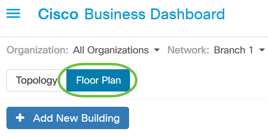
Step 6. Click on the Add New Building button.

Step 7. Enter a name for the building that houses the floor into the New Building field.
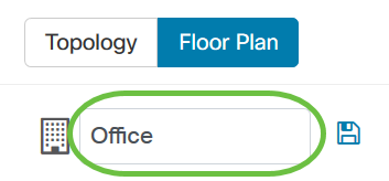
Note: In this example, Office is used as the building name.
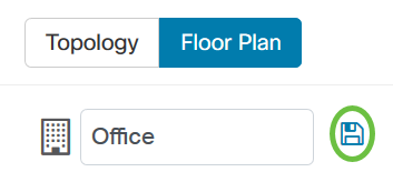
Step 8. Click Save.
Step 9. Drag and drop an image file containing the floor plan onto the target area for the new floor. Supported image formats are .png, .gif, and .jpg. The maximum image size is up to 500 KB.

Note: Alternatively, you can click on the target area to upload an image from your computer.
Step 10. Enter the floor name into the New Floor field.
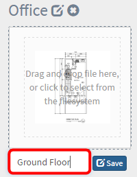
Note: In this example, Ground Floor is used as the floor name.
Step 11. Click Save.
Step 12. Repeat steps 6 to 7 for each floor with network devices.

Step 13. Repeat steps 3 to 8 for each building.
You should now have created new buildings and floor plans.
Edit the Floor Plan
Step 1. Click the Edit button next to the building name to edit a name.
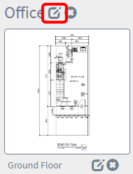
Step 2. Enter the new building name in the Building Name field.

Step 3. Click the Save button.
Step 4. Click the Edit button next to the floor name to edit a name.
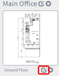
Step 5. Enter the new floor name in the Floor Name field.
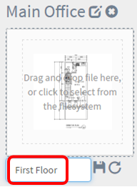
Step 6. Click the Save button.
You should now have saved the changes in your floor plans.
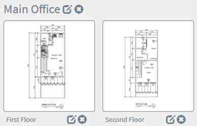
Remove a Floor Plan
Step 1. To delete a floor plan, click the Delete icon next to the floor plan name that you want to remove.
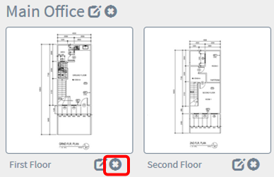
Step 2. Click Ok to proceed.

Step 3. To delete a building , click the Delete icon next to the building name that you want to remove.
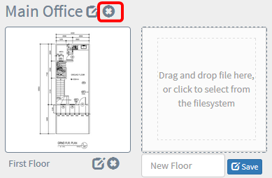
Step 4. Click Ok to proceed.

You should now have removed your floor plans.
Manage Devices in the Floor Plan
You can manage the floor plans for the site and place your network devices in order to document the location of your device. The following steps guide you through this process.
Add Network Devices on a Floor Plan
Step 1. Click a floor plan.
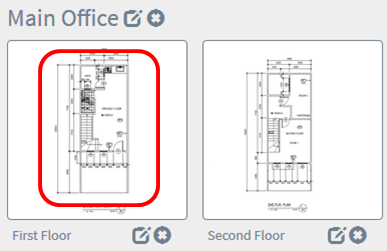
Note: In this example, First Floor in the Main Office is chosen.
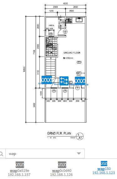
Step 2. To place a device on the floor plan, enter the device name or IP address into the search box at the bottom of the screen. As you type, the matching devices will be displayed. Grayed-out device icons represent devices that have already been placed on a floor plan.
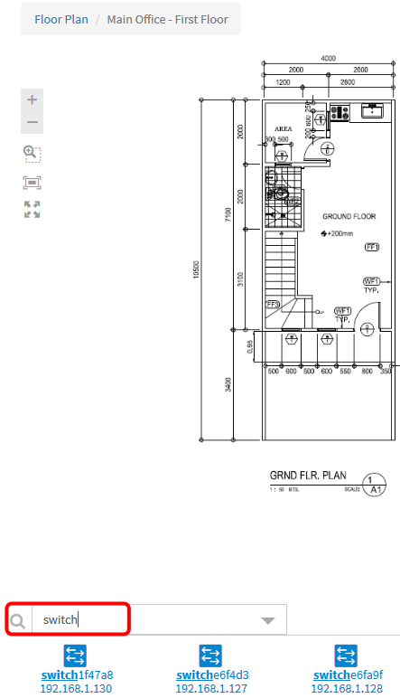
Note: In this example, switch is used to search.
Step 3. Click on a device to add it to the floor plan.

Note: In this example, switch1f47a8 is chosen.
The chosen device will be displayed in the floor plan.
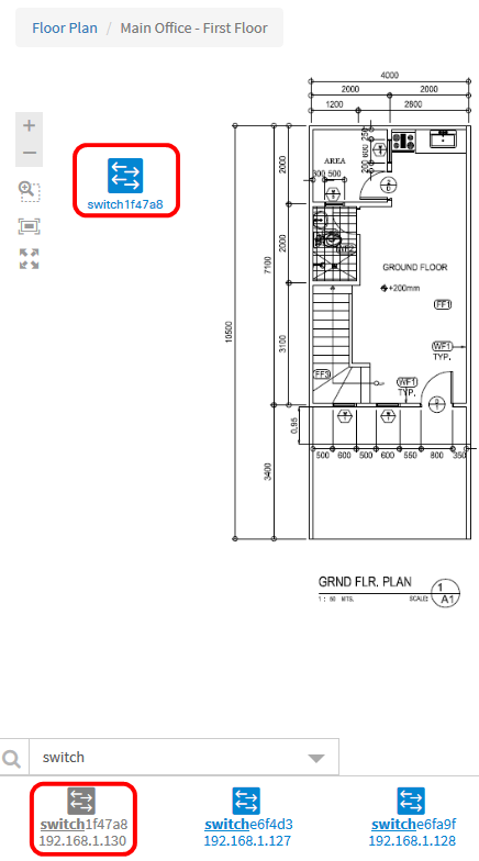
You should now have added network devices in your floor plan.
Position Network Devices on a Floor Plan
Step 1. Click on a device to add it to the floor plan.
Important: If you choose a device that has already been placed on another floor plan, it will be removed and added to this one.
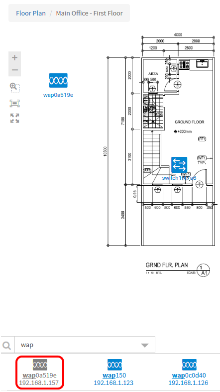
Step 2. Click and drag the device to move into the desired location in the floor plan.
Step 3. Repeat steps 2 and 3 until all devices have been added to the floor plan.
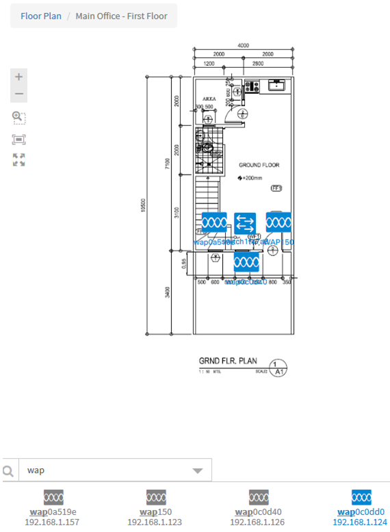
You should now have positioned your network devices on your floor plan.
Remove a Device from the Floor Plan
Step 1. Click the device that you want to remove.
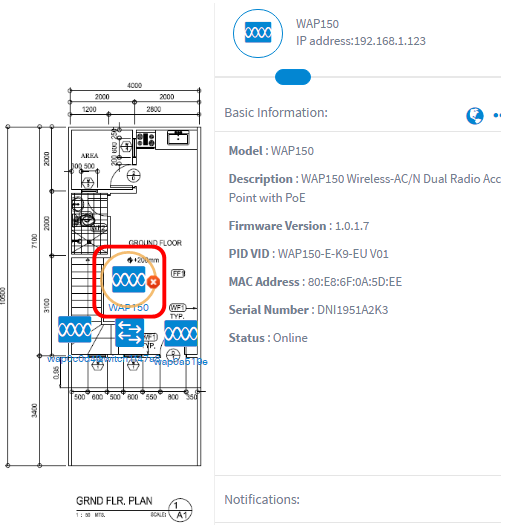
Note: In this example, a WAP150 is chosen.
Step 2. Click on the Delete button that is displayed to remove the device from the floor plan.
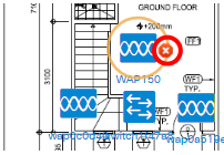
You should now have removed a device from the floor plan.
Contact Cisco
- Open a Support Case

- (Requires a Cisco Service Contract)
 Feedback