Configure FTD Clustering on FP9300 (intra-chassis)
Available Languages
Download Options
Bias-Free Language
The documentation set for this product strives to use bias-free language. For the purposes of this documentation set, bias-free is defined as language that does not imply discrimination based on age, disability, gender, racial identity, ethnic identity, sexual orientation, socioeconomic status, and intersectionality. Exceptions may be present in the documentation due to language that is hardcoded in the user interfaces of the product software, language used based on RFP documentation, or language that is used by a referenced third-party product. Learn more about how Cisco is using Inclusive Language.
Contents
Introduction
This document describes how to configure and verify Cluster Feature on the FPR9300 device.
Caution: The information provided in this document covers the initial installation/configuration of the cluster. This document is not applicable to a unit replacement (Return Material Authorization - RMA) procedure
Prerequisites
Requirements
There are no specific requirements for this document.
Components Used
The information in this document is based on these software and hardware versions:
- Cisco Firepower 9300 Security Appliance running 1.1(4.95)
- Firepower Threat Defense (FTD) running 6.0.1 (build 1213)
- FireSIGHT Management Center (FMC) running 6.0.1.1 (build 1023)
Lab completion time: 1 hour.
The information in this document was created from the devices in a specific lab environment. All of the devices used in this document started with a cleared (default) configuration. If your network is live, ensure that you understand the potential impact of any command.
Background Information
- On the FPR9300 with FTD appliance, you can configure intra-chassis Clustering on all supported versions.
- Inter-chassis clustering was introduced in 6.2.
- Port-channel 48 is created as a cluster-control link. For intra-chassis clustering, this link utilizes the Firepower 9300 backplane for cluster communications.
- Individual data interfaces are not supported, with the exception of a management interface.
- Management interface is assigned to all units in the cluster.
Configure
Network Diagram

Task 1. Create Necessary Interfaces for FTD Cluster
Task requirement:
Create a Cluster, a Management interface, and a Port-channel Data interface.
Solution:
Step 1. Create a Port channel Data interface.
In order to create a new interface, you have to log into FPR9300 Chassis Manager and Navigate to Interfaces tab.
Select Add Port Channel and create a new Port Channel Interface with these parameters:
|
Port Channel ID |
5 |
|
Type |
Data |
|
Enable |
Yes |
|
Member ID |
Ethernet1/3, Ethernet 1/4 |
Select OK to save the configuration as shown in the image.

Step 2. Create a Management Interface.
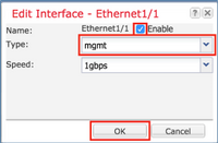
On the Interfaces tab, choose the interface, click on Edit and configure the Management Type interface.
Click OK to save the configuration as shown in the image.
Step 3. Create Cluster-Control Link Interface.
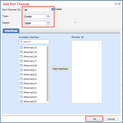
Click on Add Port Channel button and create a new Port Channel Interface with these parameters and as shown in the image.
|
Port Channel ID |
48 |
|
Type |
Cluster |
|
Enable |
Yes |
|
Member ID |
- |
Task 2. Create FTD Cluster
Task requirement:
Create an FTD Cluster unit.
Solution:
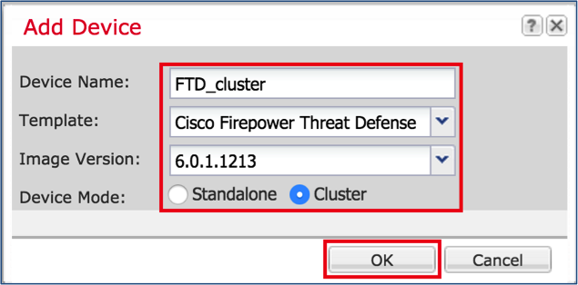
Step 1. Navigate to Logical Devices and click on Add Device button.
Create the FTD Clustering as follows:
|
Device Name |
FTD_cluster |
|
Template |
Cisco Firepower Threat Defense |
|
Image Version |
6.0.1.1213 |
|
Device Mode |
Cluster |
In order to add the device, click OK as shown in the image.
Step 2. Configure and deploy FTD Cluster.
After you create an FTD device, you are redirected to the Provisioning- device_name window.
Click on the device icon to start the configuration as shown in the image.
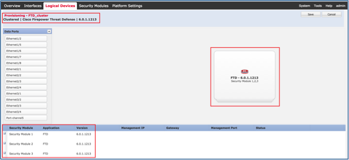
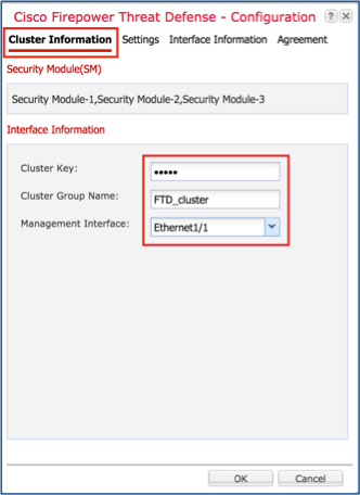
Configure the FTD Cluster Information tab with these settings and as shown in the image.
|
Cluster key |
cisco |
|
Cluster Group Name |
FTD_cluster |
|
Management Interface |
Ethernet1/1 |
Configure the FTD Settings tab with these settings and as shown in the image.
|
Registration Key |
cisco |
|
Password |
Admin123 |
|
Firepower Management Center IP |
10.62.148.73 |
|
Search Domains |
cisco.com |
|
Firewall Mode |
Routed |
|
DNS Servers |
173.38.200.100 |
|
Fully Qualified Hostname |
ksec-fpr9k-1-1-3.cisco.com |
|
Eventing Interface |
None |

Configure the FTD Interface Information tab with these settings and as shown in the image.
|
Address Type |
IPv4 Only |
|
Security Module 1 |
|
|
Management IP |
10.62.148.67 |
|
Network Mask |
255.255.255.128 |
|
Gateway |
10.62.148.1 |
|
Security Module 2 |
|
|
Management IP |
10.62.148.68 |
|
Network Mask |
255.255.255.128 |
|
Gateway |
10.62.148.1 |
|
Security Module 3 |
|
|
Management IP |
10.62.148.69 |
|
Network Mask |
255.255.255.128 |
|
Gateway |
10.62.148.1 |

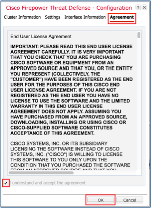
Accept the Agreement on the Agreement tab and click OK as shown in the image.
Step 3. Assign Data Interfaces to FTD.
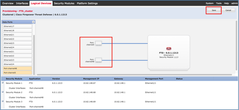
Expand the Data Ports area and click on each interface you want to assign to FTD. After completion, select Save to create an FTD cluster as shown in the image.
Wait for a few minutes for the cluster to be deployed, after which the master unit election occurs.
Verification:
- From the FPR9300 GUI as shown in the image.

- From the FPR9300 CLI
FPR9K-1-A#
FPR9K-1-A# scope ssa
FPR9K-1-A /ssa # show app-instance
Application Name     Slot ID    Admin State     Operational State    Running Version Startup Version Cluster Oper State
-------------------- ---------- --------------- -------------------- --------------- --------------- ------------------
ftd                  1          Enabled         Online               6.0.1.1213      6.0.1.1213      In Cluster
ftd                  2          Enabled         Online               6.0.1.1213      6.0.1.1213      In Cluster
ftd                  3          Enabled         Online               6.0.1.1213      6.0.1.1213      In Cluster
- From the LINA (ASA) CLI
firepower# show cluster info
Cluster FTD_cluster: On
    Interface mode: spanned
    This is "unit-1-1" in state MASTER
        ID        : 0
        Version   : 9.6(1)
        Serial No.: FLM19216KK6
        CCL IP    : 127.2.1.1
        CCL MAC   : 0015.c500.016f
        Last join : 21:51:03 CEST Aug 8 2016
        Last leave: N/A
Other members in the cluster:
    Unit "unit-1-3" in state SLAVE
        ID        : 1
        Version   : 9.6(1)
        Serial No.: FLM19206H7T
        CCL IP    : 127.2.1.3
        CCL MAC   : 0015.c500.018f
        Last join : 21:51:05 CEST Aug 8 2016
        Last leave: N/A
    Unit "unit-1-2" in state SLAVE
        ID        : 2
        Version   : 9.6(1)
        Serial No.: FLM19206H71
        CCL IP    : 127.2.1.2
        CCL MAC   : 0015.c500.019f
        Last join : 21:51:30 CEST Aug 8 2016
        Last leave: N/A
firepower# cluster exec show cluster interface-mode
cluster interface-mode spanned


unit-1-3:*************************************************************
cluster interface-mode spanned


unit-1-2:*************************************************************
cluster interface-mode spanned
firepower#
firepower# cluster exec show cluster history
==========================================================================
From State           To State             Reason
==========================================================================
21:49:25 CEST Aug 8 2016
DISABLED             DISABLED             Disabled at startup

21:50:18 CEST Aug 8 2016
DISABLED             ELECTION             Enabled from CLI

21:51:03 CEST Aug 8 2016
ELECTION             MASTER_POST_CONFIG   Enabled from CLI

21:51:03 CEST Aug 8 2016
MASTER_POST_CONFIG   MASTER               Master post config done and waiting for ntfy

==========================================================================


unit-1-3:*************************************************************
==========================================================================
From State           To State             Reason
==========================================================================
21:49:44 CEST Aug 8 2016
DISABLED             DISABLED             Disabled at startup

21:50:37 CEST Aug 8 2016
DISABLED             ELECTION             Enabled from CLI

21:50:37 CEST Aug 8 2016
ELECTION             ONCALL               Received cluster control message

21:50:41 CEST Aug 8 2016
ONCALL               ELECTION            Received cluster control message

21:50:41 CEST Aug 8 2016
ELECTION             ONCALL               Received cluster control message

21:50:46 CEST Aug 8 2016
ONCALL               ELECTION             Received cluster control message

21:50:46 CEST Aug 8 2016
ELECTION             ONCALL               Received cluster control message

21:50:51 CEST Aug 8 2016
ONCALL               ELECTION             Received cluster control message

21:50:51 CEST Aug 8 2016
ELECTION             ONCALL                Received cluster control message

21:50:56 CEST Aug 8 2016
ONCALL               ELECTION             Received cluster control message

21:50:56 CEST Aug 8 2016
ELECTION             ONCALL               Received cluster control message

21:51:01 CEST Aug 8 2016
ONCALL               ELECTION             Received cluster control message

21:51:01 CEST Aug 8 2016
ELECTION             ONCALL               Received cluster control message

21:51:04 CEST Aug 8 2016
ONCALL               SLAVE_COLD          Received cluster control message

21:51:04 CEST Aug 8 2016
SLAVE_COLD           SLAVE_APP_SYNC       Client progression done

21:51:05 CEST Aug 8 2016
SLAVE_APP_SYNC       SLAVE_CONFIG         Slave application configuration sync done

21:51:17 CEST Aug 8 2016
SLAVE_CONFIG         SLAVE_BULK_SYNC       Configuration replication finished

21:51:29 CEST Aug 8 2016
SLAVE_BULK_SYNC       SLAVE                 Configuration replication finished

==========================================================================


unit-1-2:*************************************************************
==========================================================================
From State           To State             Reason
==========================================================================
21:49:24 CEST Aug 8 2016
DISABLED             DISABLED             Disabled at startup

21:50:16 CEST Aug 8 2016
DISABLED             ELECTION             Enabled from CLI

21:50:17 CEST Aug 8 2016
ELECTION              ONCALL               Received cluster control message

21:50:21 CEST Aug 8 2016
ONCALL               ELECTION             Received cluster control message

21:50:21 CEST Aug 8 2016
ELECTION             ONCALL               Received cluster control message

21:50:26 CEST Aug 8 2016
ONCALL               ELECTION             Received cluster control message

21:50:26 CEST Aug 8 2016
ELECTION             ONCALL               Received cluster control message

21:50:31 CEST Aug 8 2016
ONCALL               ELECTION             Received cluster control message

21:50:31 CEST Aug 8 2016
ELECTION             ONCALL               Received cluster control message

21:50:36 CEST Aug 8 2016
ONCALL               ELECTION             Received cluster control message

21:50:36 CEST Aug 8 2016
ELECTION             ONCALL               Received cluster control message

21:50:41 CEST Aug 8 2016
ONCALL               ELECTION             Received cluster control message

21:50:41 CEST Aug 8 2016
ELECTION             ONCALL               Received cluster control message

21:50:46 CEST Aug 8 2016
ONCALL               ELECTION             Received cluster control message

21:50:46 CEST Aug 8 2016
ELECTION             ONCALL                Received cluster control message

21:50:51 CEST Aug 8 2016
ONCALL               ELECTION             Received cluster control message

21:50:51 CEST Aug 8 2016
ELECTION             ONCALL               Received cluster control message

21:50:56 CEST Aug 8 2016
ONCALL               ELECTION             Received cluster control message

21:50:56 CEST Aug 8 2016
ELECTION             ONCALL               Received cluster control message

21:51:01 CEST Aug 8 2016
ONCALL               ELECTION             Received cluster control message

21:51:01 CEST Aug 8 2016
ELECTION             ONCALL               Received cluster control message

21:51:06 CEST Aug 8 2016
ONCALL               ELECTION             Received cluster control message

21:51:06 CEST Aug 8 2016
ELECTION             ONCALL               Received cluster control message

21:51:12 CEST Aug 8 2016
ONCALL               ELECTION             Received cluster control message

21:51:12 CEST Aug 8 2016
ELECTION              ONCALL               Received cluster control message

21:51:17 CEST Aug 8 2016
ONCALL               ELECTION             Received cluster control message

21:51:17 CEST Aug 8 2016
ELECTION             ONCALL               Received cluster control message

21:51:22 CEST Aug 8 2016
ONCALL               ELECTION             Received cluster control message

21:51:22 CEST Aug 8 2016
ELECTION             ONCALL               Received cluster control message

21:51:27 CEST Aug 8 2016
ONCALL               ELECTION             Received cluster control message

21:51:27 CEST Aug 8 2016
ELECTION             ONCALL               Received cluster control message

21:51:30 CEST Aug 8 2016
ONCALL               SLAVE_COLD          Received cluster control message

21:51:30 CEST Aug 8 2016
SLAVE_COLD           SLAVE_APP_SYNC       Client progression done

21:51:31 CEST Aug 8 2016
SLAVE_APP_SYNC       SLAVE_CONFIG         Slave application configuration sync done

21:51:43 CEST Aug 8 2016
SLAVE_CONFIG         SLAVE_BULK_SYNC       Configuration replication finished

21:51:55 CEST Aug 8 2016
SLAVE_BULK_SYNC       SLAVE                 Configuration replication finished

==========================================================================
firepower#
Task 3. Register FTD Cluster to FMC
Task requirement:
Add the logical devices to the FMC and then group them into a cluster.
Solution:
Step 1. Add Logical Devices to the FMC. As from FMC version 6.3, you must register only one FTD device (recommended to be the Master). The rest of the FTDs are auto-discovered by the FMC.
Log into the FMC and navigate to Devices > Device Management tab and click Add Device.
Add the first logical device with the settings as mentioned in the image.
Click on Register to start registration.
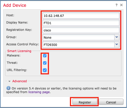
Verification is as shown in the image.

Task 4. Configure Port-Channel Sub-Interfaces on FMC
Task requirement:
Configure sub-interfaces for the Port-channel Data interface.
Solution:
Step 1. From the FMC GUI, select FTD_cluster Edit button.
Navigate to Interfaces tab and click on the Add Interfaces > Sub Interface as shown in the image.

Configure the first sub-interface with these details. Select OK to apply the changes and as shown in the images.
|
Name |
Inside |
|
General tab |
|
|
Interface |
Port-channel5 |
|
Sub-interface ID |
201 |
|
VLAN ID |
201 |
|
IPv4 tab |
|
|
IP Type |
Use Static IP |
|
IP Address |
192.168.75.10/24 |


Configure the second sub-interface with these details.
|
Name |
Outside |
|
General tab |
|
|
Interface |
Port-channel5 |
|
Sub-interface ID |
210 |
|
VLAN ID |
210 |
|
IPv4 tab |
|
|
IP Type |
Use Static IP |
|
IP Address |
192.168.76.10/24 |
Click OK to create the sub-interface. Click Save and then Deploy changes to the FTD_cluster as shown in the image.
Verification:

Task 5. Verify Basic Connectivity
Task requirement:
Create a capture and check the connectivity between two VMs.
Solution:
Step 1. Create captures on all cluster units.
Navigate to LINA (ASA) CLI of Master unit and create captures for the Inside and Outside interfaces.
firepower#
firepower# cluster exec capture capi interface inside match icmp any any
unit-1-1(LOCAL):******************************************************


unit-1-3:*************************************************************


unit-1-2:*************************************************************
firepower#
firepower# cluster exec capture capo interface outside match icmp any any
unit-1-1(LOCAL):******************************************************


unit-1-3:*************************************************************


unit-1-2:*************************************************************
firepower#
Verification:
firepower# cluster exec show capture
unit-1-1(LOCAL):******************************************************
capture capi type raw-data interface Inside [Capturing - 0 bytes]
  match icmp any any
capture capo type raw-data interface Outside [Capturing - 0 bytes]
  match icmp any any


unit-1-3:*************************************************************
capture capi type raw-data interface Inside [Capturing - 0 bytes]
  match icmp any any
capture capo type raw-data interface Outside [Capturing - 0 bytes]
  match icmp any any


unit-1-2:*************************************************************
capture capi type raw-data interface Inside [Capturing - 0 bytes]
  match icmp any any
capture capo type raw-data interface Outside [Capturing - 0 bytes]
  match icmp any any
firepower#
Step 2. Do the ping test from the VM1 to VM2.
Do the test with 4 packets. Check the capture output after the test:
firepower# cluster exec show capture
unit-1-1(LOCAL):******************************************************
capture capi type raw-data interface Inside [Capturing - 0 bytes]
  match icmp any any
capture capo type raw-data interface Outside [Capturing - 0 bytes]
  match icmp any any


unit-1-3:*************************************************************
capture capi type raw-data interface Inside [Capturing - 752 bytes]
  match icmp any any
capture capo type raw-data interface Outside [Capturing - 752 bytes]
  match icmp any any


unit-1-2:*************************************************************
capture capi type raw-data interface Inside [Capturing - 0 bytes]
  match icmp any any
capture capo type raw-data interface Outside [Capturing - 0 bytes]
  match icmp any any
firepower#
Run the command in order to check capture output on the specific unit:
firepower# cluster exec unit unit-1-3 show capture capi

8 packets captured

   1: 12:58:36.162253       802.1Q vlan#201 P0 192.168.75.100 > 192.168.76.100: icmp: echo request
   2: 12:58:36.162955       802.1Q vlan#201 P0 192.168.76.100 > 192.168.75.100: icmp: echo reply
   3: 12:58:37.173834       802.1Q vlan#201 P0 192.168.75.100 > 192.168.76.100: icmp: echo request
   4: 12:58:37.174368       802.1Q vlan#201 P0 192.168.76.100 > 192.168.75.100: icmp: echo reply
   5: 12:58:38.187642       802.1Q vlan#201 P0 192.168.75.100 > 192.168.76.100: icmp: echo request
   6: 12:58:38.188115       802.1Q vlan#201 P0 192.168.76.100 > 192.168.75.100: icmp: echo reply
   7: 12:58:39.201832       802.1Q vlan#201 P0 192.168.75.100 > 192.168.76.100: icmp: echo request
   8: 12:58:39.202321       802.1Q vlan#201 P0 192.168.76.100 > 192.168.75.100: icmp: echo reply
8 packets shown

firepower# cluster exec unit unit-1-3 show capture capo

8 packets captured

   1: 12:58:36.162543       802.1Q vlan#210 P0 192.168.75.100 > 192.168.76.100: icmp: echo request
   2: 12:58:36.162894       802.1Q vlan#210 P0 192.168.76.100 > 192.168.75.100: icmp: echo reply
   3: 12:58:37.174002       802.1Q vlan#210 P0 192.168.75.100 > 192.168.76.100: icmp: echo request
   4: 12:58:37.174307       802.1Q vlan#210 P0 192.168.76.100 > 192.168.75.100: icmp: echo reply
   5: 12:58:38.187764       802.1Q vlan#210 P0 192.168.75.100 > 192.168.76.100: icmp: echo request
   6: 12:58:38.188085       802.1Q vlan#210 P0 192.168.76.100 > 192.168.75.100: icmp: echo reply
   7: 12:58:39.201954       802.1Q vlan#210 P0 192.168.75.100 > 192.168.76.100: icmp: echo request
   8: 12:58:39.202290       802.1Q vlan#210 P0 192.168.76.100 > 192.168.75.100: icmp: echo reply
8 packets shown
firepower#
After you finish this task, delete the captures with the next command:
firepower# cluster exec no capture capi
unit-1-1(LOCAL):******************************************************


unit-1-3:*************************************************************


unit-1-2:*************************************************************

firepower# cluster exec no capture capo
unit-1-1(LOCAL):******************************************************


unit-1-3:*************************************************************


unit-1-2:*************************************************************
Step 3. Download a file from VM2 to VM1.
VM1 was pre-configured as an FTP server, VM2 as an FTP client.
Create new captures with these:
firepower# cluster exec capture capi interface inside match ip host 192.168.75.100 host 192.168.76.100
unit-1-1(LOCAL):******************************************************


unit-1-3:*************************************************************


unit-1-2:*************************************************************

firepower# cluster exec capture capo interface outside match ip host 192.168.775.100 host 192.168.76.100
unit-1-1(LOCAL):******************************************************


unit-1-3:*************************************************************


unit-1-2:*************************************************************
Download the file from VM2 to VM1, with the use of FTP client.
Check the show conn output:
firepower# cluster exec show conn all
unit-1-1(LOCAL):******************************************************
20 in use, 21 most used
Cluster:
	fwd connections: 0 in use, 2 most used
	dir connections: 0 in use, 52 most used
	centralized connections: 0 in use, 6 most used

TCP Outside  192.168.76.100:49175 Inside  192.168.75.100:21, idle 0:00:32, bytes 665, flags UIOeN
UDP cluster  255.255.255.255:49495 NP Identity Ifc  127.2.1.1:49495, idle 0:00:00, bytes 17858058, flags -
TCP cluster  127.2.1.3:10844 NP Identity Ifc  127.2.1.1:38296, idle 0:00:33, bytes 5496, flags UI
…….
TCP cluster  127.2.1.3:59588 NP Identity Ifc  127.2.1.1:10850, idle 0:00:33, bytes 132, flags UO


unit-1-3:*************************************************************
12 in use, 16 most used
Cluster:
	fwd connections: 0 in use, 4 most used
	dir connections: 1 in use, 10 most used
	centralized connections: 0 in use, 0 most used

TCP Outside  192.168.76.100:49175 Inside  192.168.75.100:21, idle 0:00:34, bytes 0, flags  y
TCP cluster  127.2.1.1:10851 NP Identity Ifc  127.2.1.3:48493, idle 0:00:52, bytes 224, flags UI
……..
TCP cluster  127.2.1.1:64070 NP Identity Ifc  127.2.1.3:10847, idle 0:00:11, bytes 806, flags UO


unit-1-2:*************************************************************
12 in use, 15 most used
Cluster:
	fwd connections: 0 in use, 2 most used
	dir connections: 0 in use, 3 most used
	centralized connections: 0 in use, 0 most used

TCP cluster  127.2.1.1:10851 NP Identity Ifc  127.2.1.2:64136, idle 0:00:53, bytes 224, flags UI
……..
TCP cluster  127.2.1.1:15859 NP Identity Ifc  127.2.1.2:10847, idle 0:00:11, bytes 807, flags UO
Show capture output:
firepower# cluster exec show cap
unit-1-1(LOCAL):******************************************************
capture capi type raw-data interface Inside [Buffer Full - 523954 bytes]
  match ip host 192.168.75.100 host 192.168.76.100
capture capo type raw-data interface Outside [Buffer Full - 524028 bytes]
  match ip host 192.168.75.100 host 192.168.76.100


unit-1-3:*************************************************************
capture capi type raw-data interface Inside [Buffer Full - 524062 bytes]
  match ip host 192.168.75.100 host 192.168.76.100
capture capo type raw-data interface Outside [Buffer Full - 524228 bytes]
  match ip host 192.168.75.100 host 192.168.76.100


unit-1-2:*************************************************************
capture capi type raw-data interface Inside [Capturing - 0 bytes]
  match ip host 192.168.75.100 host 192.168.76.100
capture capo type raw-data interface Outside [Capturing - 0 bytes]
  match ip host 192.168.75.100 host 192.168.76.100
Cluster Capture from Chassis Manager UI
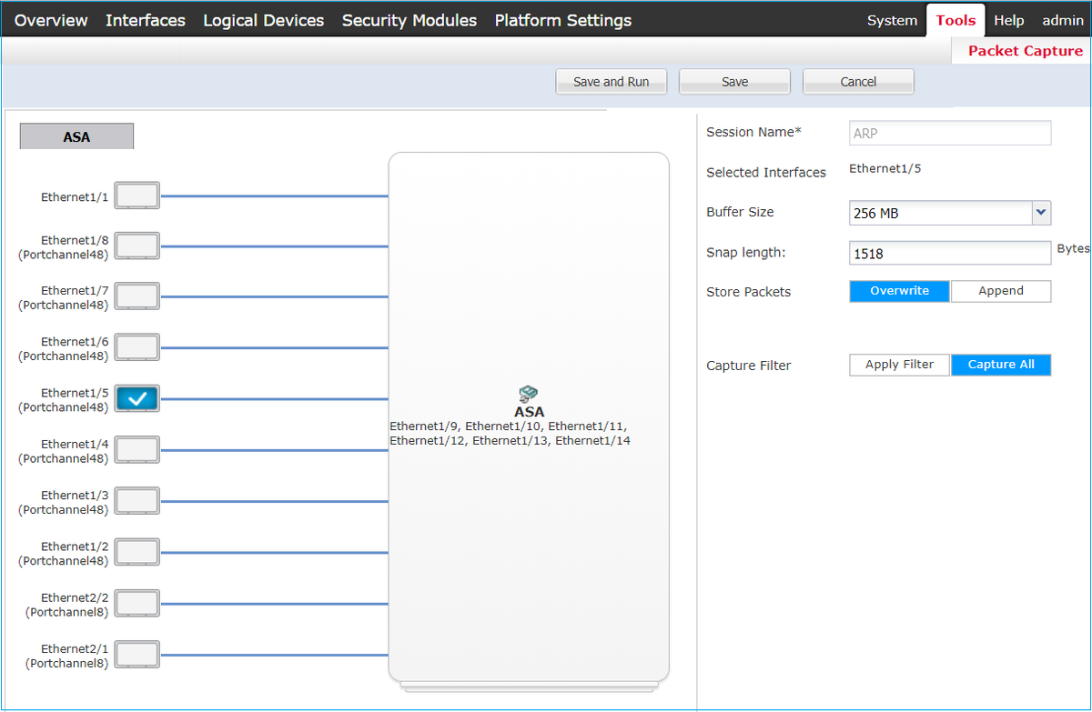
In the following image you can see a 3-unit cluster on FPR9300 with 2 Port-Channels (8 and 48). The logical devices are ASAs, but in the case of FTD will be the same concept.The important thing to remember is that although there are 3 cluster units, from capture point of view there is only one logical device:

Task 6. Delete a Slave Device from the Cluster
Task requirement:
Log into the FMC and delete the Slave unit from the cluster.
Solution:
Step 1. Log into the FMC and navigate to Device > Device Management.
Click the trash icon next to the Slave unit as shown in the image.

The confirmation window appears. Select Yes to confirm as shown in the image.

Verification:
- From the FMC as shown in the image.

- From the FXOS CLI.
FPR9K-1-A# scope ssa
FPR9K-1-A /ssa # show app-instance
Application Name     Slot ID    Admin State     Operational State    Running Version Startup Version Cluster Oper State
-------------------- ---------- --------------- -------------------- --------------- --------------- ------------------
ftd                  1          Enabled         Online               6.0.1.1213      6.0.1.1213      In Cluster
ftd                  2          Enabled         Online               6.0.1.1213      6.0.1.1213      In Cluster
ftd                  3          Enabled         Online               6.0.1.1213      6.0.1.1213      In Cluster
- From the LINA (ASA) CLI.
firepower# show cluster info
Cluster FTD_cluster: On
    Interface mode: spanned
    This is "unit-1-1" in state MASTER
        ID        : 0
        Version   : 9.6(1)
        Serial No.: FLM19216KK6
        CCL IP    : 127.2.1.1
        CCL MAC   : 0015.c500.016f
        Last join : 21:51:03 CEST Aug 8 2016
        Last leave: N/A
Other members in the cluster:
    Unit "unit-1-3" in state SLAVE
        ID        : 1
        Version   : 9.6(1)
        Serial No.: FLM19206H7T
        CCL IP    : 127.2.1.3
        CCL MAC   : 0015.c500.018f
        Last join : 21:51:05 CEST Aug 8 2016
        Last leave: N/A
    Unit "unit-1-2" in state SLAVE
        ID        : 2
        Version   : 9.6(1)
        Serial No.: FLM19206H71
        CCL IP    : 127.2.1.2
        CCL MAC   : 0015.c500.019f
        Last join : 21:51:30 CEST Aug 8 2016
        Last leave: N/A
firepower#
Note: The device was unregistered from the FMC but it is still a cluster member on the FPR9300.
Verify
Use this section in order to confirm that your configuration works properly.
Verification is completed and covered in individual tasks.
Troubleshoot
There is currently no specific troubleshooting information available for this configuration.
Related Information
- All versions of the Cisco Firepower Management Center configuration guide can be found here:
https://www.cisco.com/c/en/us/td/docs/security/firepower/roadmap/firepower-roadmap.html#id_47280.
- All versions of the FXOS Chassis Manager and CLI configuration guides can be found here:
https://www.cisco.com/c/en/us/td/docs/security/firepower/fxos/roadmap/fxos-roadmap.html#pgfId-121950.
- Cisco Global Technical Assistance Center (TAC) strongly recommends this visual guide for in-depth practical knowledge on Cisco Firepower Next Generation Security Technologies, including the ones mentioned in this article:
http://www.ciscopress.com/title/9781587144806.
- For all Configuration and Troubleshooting TechNotes that pertains to Firepower technologies.
https://www.cisco.com/c/en/us/support/security/defense-center/tsd-products-support-series-home.html.
Contributed by Cisco Engineers
- Olha YakovenkoCisco TAC Engineer
- John LongCisco TAC Engineer
Contact Cisco
- Open a Support Case

- (Requires a Cisco Service Contract)
 Feedback