ASA/PIX: Static IP Addressing for IPSec VPN Client with CLI and ASDM Configuration Example
Available Languages
Contents
Introduction
This document describes how to configure the Cisco 5500 Series Adaptive Security Appliance (ASA) to provide the Static IP address to the VPN client with the Adaptive Security Device Manager (ASDM) or CLI. The ASDM delivers world-class security management and monitoring through an intuitive, easy-to-use Web-based management interface. Once the Cisco ASA configuration is complete, it can be verified with the Cisco VPN Client.
Refer to PIX/ASA 7.x and Cisco VPN Client 4.x with Windows 2003 IAS RADIUS (Against Active Directory) Authentication Configuration Example in order to set up the remote access VPN connection between a Cisco VPN Client (4.x for Windows) and the PIX 500 Series Security Appliance 7.x. The remote VPN Client user authenticates against the Active Directory with a Microsoft Windows 2003 Internet Authentication Service (IAS) RADIUS server.
Refer to PIX/ASA 7.x and Cisco VPN Client 4.x for Cisco Secure ACS Authentication Configuration Example in order to set up a remote access VPN connection between a Cisco VPN Client (4.x for Windows) and the PIX 500 Series Security Appliance 7.x with a Cisco Secure Access Control Server (ACS version 3.2) for extended authentication (Xauth).
Prerequisites
Requirements
This document assumes that the ASA is fully operational and configured to allow the Cisco ASDM or CLI to make configuration changes.
Note: Refer to Allowing HTTPS Access for ASDM or PIX/ASA 7.x: SSH on the Inside and Outside Interface Configuration Example to allow the device to be remotely configured by the ASDM or Secure Shell (SSH).
Components Used
The information in this document is based on these software and hardware versions:
-
Cisco Adaptive Security Appliance Software Version 7.x and later
-
Adaptive Security Device Manager Version 5.x and later
-
Cisco VPN Client Version 4.x and later
The information in this document was created from the devices in a specific lab environment. All of the devices used in this document started with a cleared (default) configuration. If your network is live, make sure that you understand the potential impact of any command.
Related Products
This configuration can also be used with Cisco PIX Security Appliance Version 7.x and later.
Conventions
Refer to Cisco Technical Tips Conventions for more information on document conventions.
Configure
In this section, you are presented with the information to configure the features described in this document.
Note: Use the Command Lookup Tool (registered customers only) in order to obtain more information on the commands used in this section.
Network Diagram
This document uses this network setup:
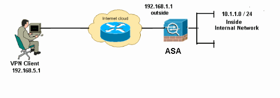
Note: The IP addressing schemes used in this configuration are not legally routable on the Internet. They are RFC 1918 addresses, which were used in a lab environment.
Configure Remote Access VPN (IPSec)
ASDM Procedure
Complete these steps in order to configure the remote access VPN:
-
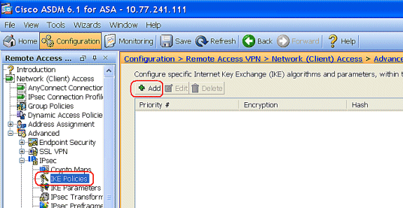
Choose Configuration > Remote Access VPN > Network (Client) Access > Advanced > IPSec > IKE Policies > Add in order to create a ISAKMP policy.
-
Provide the ISAKMP policy details.
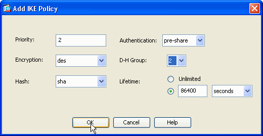
Click OK and Apply.
-
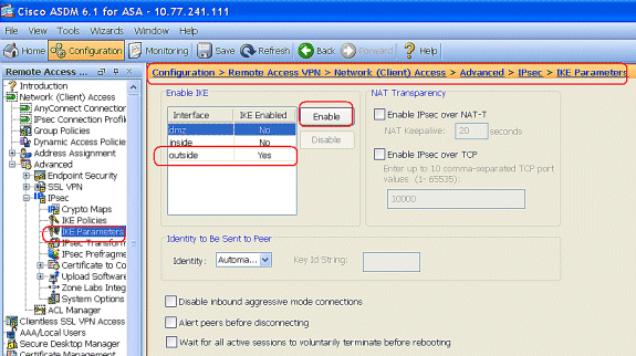
Choose Configuration > Remote Access VPN > Network (Client) Access > Advanced > IPSec > IKE Parameters to enable the IKE on the Outside Interface.
-
Choose Configuration > Remote Access VPN > Network (Client) Access > Advanced > IPSec > IPSec Transform Sets > Add in order to create the ESP-DES-SHA transform set, as shown.
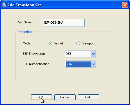
Click OK and Apply.
-
Choose Configuration > Remote Access VPN > Network (Client) Access > Advanced > IPSec > Crypto Maps > Add in order to create a crypto map with dynamic policy of priority 1, as shown.
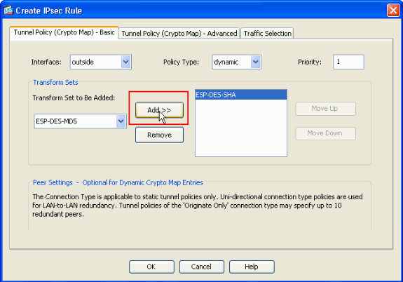
Click OK and Apply.
-
Choose Configuration > Remote Access VPN > AAA Setup > Local Users > Add in order to create the user account (for example, username - cisco123 and Password - cisco123) for VPN client access.
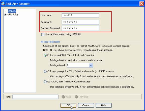
-
Go to VPN Policy and add the Static/Dedicated IP Address for user "cisco123," as follows.
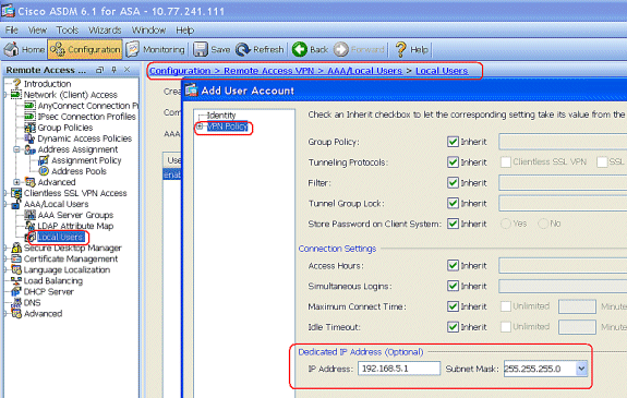
-
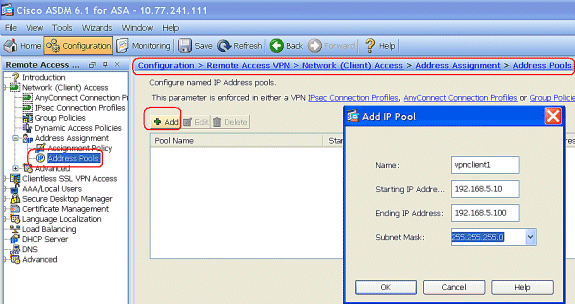
Choose Configuration > Remote Access VPN > Network (Client) Access > Address Assignment > Address Pools and click Add to add the VPN Client for VPN Client users.
-
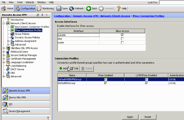
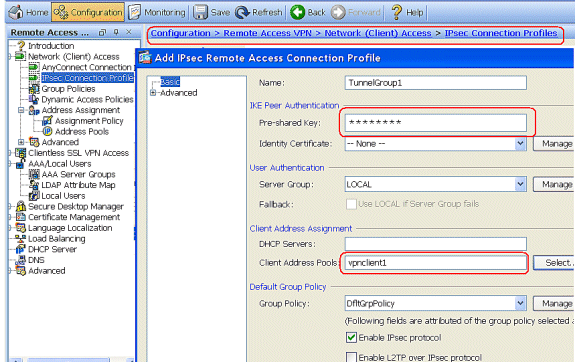
Choose Configuration > Remote Access VPN > Network (Client) Access > IPSec Connection Profiles > Add in order to add a tunnel group (for example, TunnelGroup1 and the Preshared key as cisco123), as shown.
-
Under the Basic tab, choose the server group as LOCAL for the User Authentication field.
-
Choose vpnclient1 as the Client Address Pools for the VPN Client users.
Click OK.
-
-
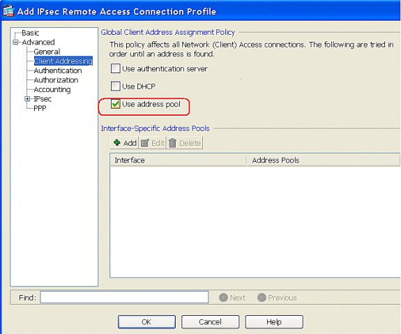
Choose Advanced > Client Addressing and check the Use address pool check box to assign the IP Address to the VPN clients.
Note: Make sure to uncheck the check boxes for Use authentication server and Use DHCP.
Click OK.
-
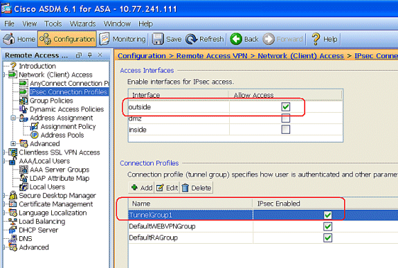
Enable the Outside interface for IPSec Access. Click Apply to proceed.
Configure the ASA/PIX with CLI
Complete these steps in order to configure the DHCP server to provide IP addresses to the VPN clients from the command line. Refer to Configuring Remote Access VPNs or Cisco ASA 5500 Series Adaptive Security Appliances-Command References for more information on each command that is used.
| Running Configuration on the ASA Device |
|---|
ASA# sh run ASA Version 8.0(2) ! !--- Specify the hostname for the Security Appliance. hostname ASA enable password 8Ry2YjIyt7RRXU24 encrypted names ! !--- Configure the outside and inside interfaces. interface Ethernet0/0 nameif inside security-level 100 ip address 10.1.1.1 255.255.255.0 ! interface Ethernet0/1 nameif outside security-level 0 ip address 192.168.1.1 255.255.255.0 ! interface Ethernet0/2 nameif DMZ security-level 50 ip address 192.168.10.2 255.255.255.0 !--- Output is suppressed. passwd 2KFQnbNIdI.2KYOU encrypted boot system disk0:/asa802-k8.bin ftp mode passive access-list 101 extended permit ip 10.1.1.0 255.255.255.0 192.168.5.0 255.255.255.0 pager lines 24 logging enable logging asdm informational mtu inside 1500 mtu outside 1500 mtu dmz 1500 ip local pool vpnclient1 192.168.5.10-192.168.5.100 mask 255.255.255.0 no failover icmp unreachable rate-limit 1 burst-size 1 !--- Specify the location of the ASDM image for ASA to fetch the image for ASDM access. asdm image disk0:/asdm-613.bin no asdm history enable arp timeout 14400 global (outside) 1 192.168.1.5 nat (inside) 0 access-list 101 nat (inside) 1 0.0.0.0 0.0.0.0 route outside 0.0.0.0 0.0.0.0 192.168.1.2 1 timeout xlate 3:00:00 timeout conn 1:00:00 half-closed 0:10:00 udp 0:02:00 icmp 0:00:02 timeout sunrpc 0:10:00 h323 0:05:00 h225 1:00:00 mgcp 0:05:00 mgcp-pat 0:05:00 timeout sip 0:30:00 sip_media 0:02:00 sip-invite 0:03:00 sip-disconnect 0:02:00 timeout uauth 0:05:00 absolute dynamic-access-policy-record DfltAccessPolicy http server enable http 0.0.0.0 0.0.0.0 inside no snmp-server location no snmp-server contact snmp-server enable traps snmp authentication linkup linkdown coldstart crypto ipsec transform-set ESP-DES-SHA esp-des esp-sha-hmac crypto dynamic-map outside_dyn_map 1 set transform-set ESP-DES-SHA crypto map outside_map 1 ipsec-isakmp dynamic outside_dyn_map !--- Specifies the interface to be used with !--- the settings defined in this configuration. crypto map outside_map interface outside !--- PHASE 1 CONFIGURATION ---! !--- This configuration uses ISAKMP policy 2. !--- The configuration commands here define the Phase !--- 1 policy parameters that are used. crypto isakmp enable outside crypto isakmp policy 2 authentication pre-share encryption des hash sha group 2 lifetime 86400 no crypto isakmp nat-traversal !--- Specifies that the IP address to the vpn clients are assigned by the local and not by AAA or dhcp. The CLI vpn-addr-assign local for VPN address assignment through ASA is hidden in the CLI provided by show run command. no vpn-addr-assign aaa no vpn-addr-assign dhcp telnet timeout 5 ssh timeout 5 console timeout 0 threat-detection basic-threat threat-detection statistics access-list ! class-map inspection_default match default-inspection-traffic ! ! policy-map type inspect dns preset_dns_map parameters message-length maximum 512 policy-map global_policy class inspection_default inspect dns preset_dns_map inspect ftp inspect h323 h225 inspect h323 ras inspect netbios inspect rsh inspect rtsp inspect skinny inspect esmtp inspect sqlnet inspect sunrpc inspect tftp inspect sip inspect xdmcp ! service-policy global_policy global ! group-policy DfltGrpPolicy attributes vpn-tunnel-protocol IPSec webvpn group-policy GroupPolicy1 internal !--- In order to identify remote access users to the Security Appliance, !--- you can also configure usernames and passwords on the device. !--- specify the IP address to assign to a particular user, use the vpn-framed-ip-address command !--- in username mode username cisco123 password ffIRPGpDSOJh9YLq encrypted username cisco123 attributes vpn-framed-ip-address 192.168.5.1 255.255.255.0 !--- Create a new tunnel group and set the connection !--- type to remote-access. tunnel-group TunnelGroup1 type remote-access tunnel-group TunnelGroup1 general-attributes address-pool vpnclient1 !--- Enter the pre-shared-key to configure the authentication method. tunnel-group TunnelGroup1 ipsec-attributes pre-shared-key * prompt hostname context Cryptochecksum:e0725ca9ccc28af488ded9ee36b7822d : end ASA# |
Cisco VPN Client Configuration
Attempt to connect to the Cisco ASA with the Cisco VPN Client in order to verify that the ASA is successfully configured.
-
Choose Start > Programs > Cisco Systems VPN Client > VPN Client.
-
Click New to launch the Create New VPN Connection Entry window.

-
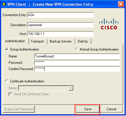
Fill in the details of your new connection.
Enter the name of the Connection Entry along with a description. Enter the outside IP address of the ASA in the Host box. Then enter the VPN Tunnel Group name (TunnelGroup1) and password (Pre-shared Key - cisco123) as configured in ASA. Click Save.
-
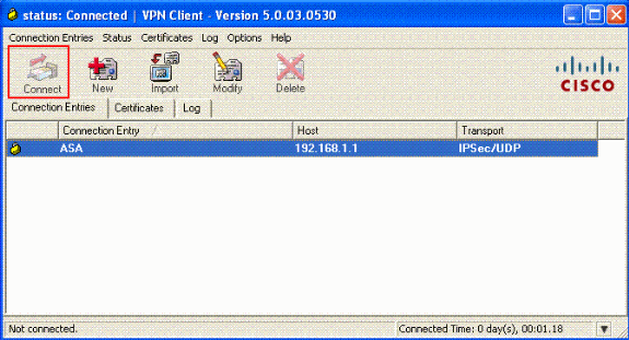
Click the connection that you want to use, and click Connect from the VPN Client main window.
-
When prompted, enter the Username : cisco123 and Password : cisco123 as configured in the ASA for Xauth, and click OK to connect to the remote network.

-
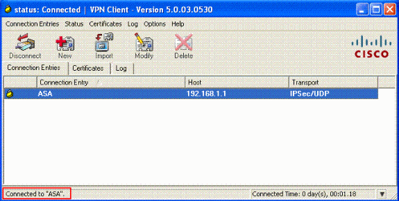
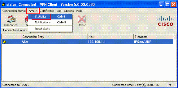
The VPN Client is connected with the ASA at the central site.
-
Once the connection is successfully established, choose Statistics from the Status menu to verify the details of the tunnel.
Verify
show Commands
Use this section to confirm that your configuration works properly.
The Output Interpreter Tool (registered customers only) (OIT) supports certain show commands. Use the OIT to view an analysis of show command output.
-
show crypto isakmp sa—Shows all current IKE Security Associations (SAs) at a peer.
-
show crypto ipsec sa—Shows the settings used by current SAs.
Troubleshoot
This section provides information you can use to troubleshoot your configuration. Sample debug output is also shown.
Note: For more information on troubleshooting Remote Access IPSec VPN refer Most Common L2L and Remote Access IPSec VPN Troubleshooting Solutions.
Clear Security Associations
When you troubleshoot, make sure to clear existent Security Associations after you make a change. In the privileged mode of the PIX, use these commands:
-
clear [crypto] ipsec sa—Deletes the active IPSec SAs. The keyword crypto is optional.
-
clear [crypto] isakmp sa—Deletes the active IKE SAs. The keyword crypto is optional.
Troubleshooting Commands
The Output Interpreter Tool (registered customers only) (OIT) supports certain show commands. Use the OIT to view an analysis of show command output.
Note: Refer to Important Information on Debug Commands before you use debug commands.
-
debug crypto ipsec 7—Displays the IPSec negotiations of Phase 2.
-
debug crypto isakmp 7—Displays the ISAKMP negotiations of Phase 1.
Related Information
- Cisco ASA 5500 Series Adaptive Security Appliances Support Page
- Cisco ASA 5500 Series Adaptive Security Appliances Command References
- Cisco PIX 500 Series Security Appliances Support Page
- Cisco PIX 500 Series Security Appliances Command Reference
- Cisco Adaptive Security Device Manager
- IPSec Negotiation/IKE Protocols Support Page
- Cisco VPN Client Support Page
- Cisco PIX Firewall Software
- Cisco Secure PIX Firewall Command References
- Security Product Field Notices (including PIX)
- Requests for Comments (RFCs)

- Technical Support & Documentation - Cisco Systems
Revision History
| Revision | Publish Date | Comments |
|---|---|---|
1.0 |
16-Feb-2009 |
Initial Release |
Contact Cisco
- Open a Support Case

- (Requires a Cisco Service Contract)


 Feedback