Introduction
This document describes the traffic flow inside the AppNav cluster. It shows how a specific TCP connection is handled in the cluster when connection optimized by Wide Area Application Services (WAAS).
AppNav is an intelligent flow distribution technology which monitors application load to manage packet redirection to external services such as WAAS. AppNav is available on AppNav I/O Module (IOM), Cisco Cloud Services Router (CSR) Ultra, Integrated Services Router (ISR) 4400 series and Aggregation Services Routers (ASR) 1000 series.
Prerequisites
Requirements
The knowledge of these topics is recommended :
- WAAS 5.x or 6.x
- AppNav or AppNav-XE
Components Used
The information in the document is based on these software and hardware versions :
- WAAS 6.2.3
- Any WAAS hardware
The information in this document was created from the devices in a specific lab environment. All of the devices used in this document started with a cleared (default) configuration. If your network is live, ensure that you understand the potential impact of any command.
AppNav Flow
This image shows the logical view of the APPNAV cluster, where it has two AppNav Controllers (ANCs) and two WAAS Nodes (WNs) or Service Nodes (SNs) connected together in one datacenter or branch site.
ANC can be AppNav IOM or APPNAV-XE. When it is APPNAV-XE, it is software based and located in the router. If it is AppNav IOM it is hardware based.
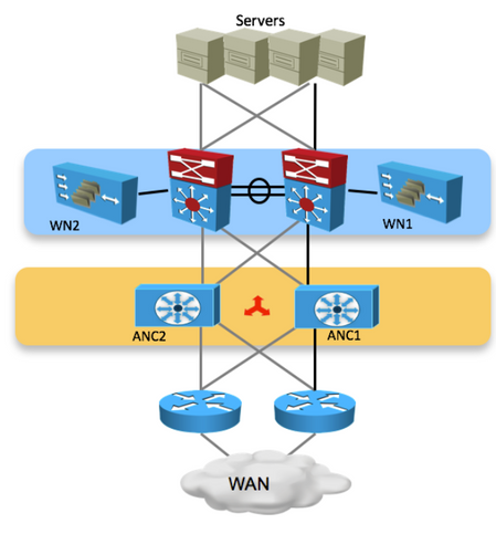
This image shows APPNAV-XE component where ANC is inside the router. Each ANC and WN in the cluster have IP connectivity and reachability between them.
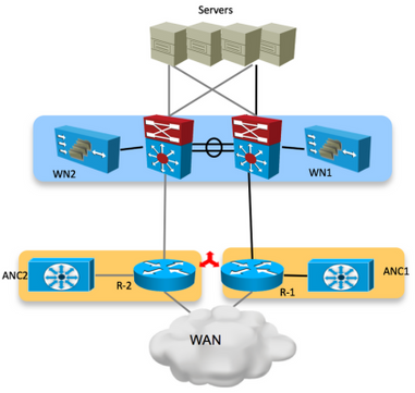
In an Active/Active WAN router (Core Switch) environment, traffic is forwarded by different devices based on their routing configuration. For some connections packets that reach the server (incoming flow) and packets that leave from the server (outgoing flow) hit the same router. There can be some connections, where different routers handle the packets that come toward the server and packets that leave from the server.
The scenario described here is when traffic comes in, it hits one router and when a packet leaves from the site, it hits the other router.
The ANC updates its peers in the cluster about each flow that it handles. So all the ANCs in the cluster have the view of each flow and which WN handles it. This ensures that the flow is handled by a specific WN and the connection is optimized.
In this image, you can see the packet flow from the client towards the server. When TCP-SYN packet gets the router and hits R-2.
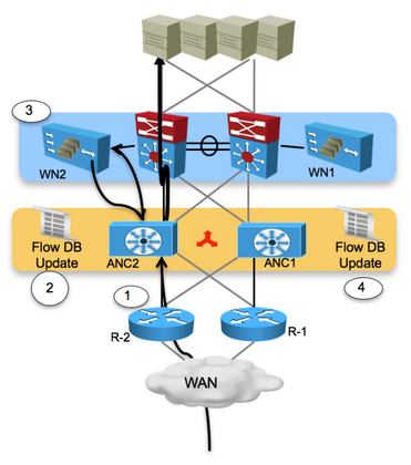
Step 1. ANC2 receives a TCP SYN packet from one of the branches that contain a WAAS device.
Step 2. The ANC2 classifies the flow, redirects it to WN2. A pending entry is made into the flow database.
Step 3. The frame is GRE-encapsulated and transmitted to WN2. WN2 processes the frame and continues the auto-discovery process.
Step 4. The other ANCs are updated with the flow information and the frame is transmitted to its destination.
This image shows how the flow is handled when it returns from server:
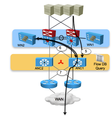
Step 5. TCP SYN-ACK frame is returned from the destination device and goes to ANC1.
Step 6. ANC1 checks the flow database, finds a match entry, and sends the response frame to WN2.
Step 7. WN2 processes the frame and returns it to ANC1, which in turn forwards the frame to the original source.
Intra-Site Asymmetric Flow
As explained AppNav can handle the asymmetric flow in intra-site traffic. This image summarizes the events when it handles asymmetric flow:
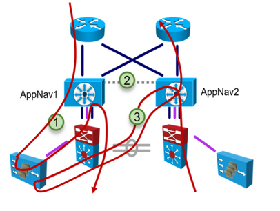
Step 1. Forward path to WAAS through AppNav1.
Step 2.Flow updates between AppNav units.
Step 3.Reverse path to the WAAS through AppNav2.
Troubleshoot
This section provides information on how to find the device which handles the flow.
Show service-insertion statistics connection
- This command dumps both optimized flows and passthrough flows together instead of separately in AppNav appliance.
- You can use output modifiers, for example '| include Passthrough' or '| exclude Passthrough' to see passthrough or optimized flows only.
Router#show service-insertion statistics connection

Collecting Records. Please wait...

Client                Server                SN-IP           AC Owned  VRF-NAME

------                ------                -----           --------   --------

11.7.0.2:50014        51.7.0.2:80           21.38.0.2        Yes        abcd

11.7.0.2:17360        51.7.0.2:80           21.38.0.2        Yes        abcd


11.7.0.2:20828        51.7.0.2:80           21.38.0.2        Yes        abcd

11.7.0.2:23625        51.7.0.2:23           Passthrough      Yes        abcd

Router#sh service-insertion statistics connection summary

Number of 2T optimized flows    = 0

Number of 3T optimized flows    = 0

Number of optimized flows       = 3

Number of pass-through flows    = 1
Related Information
