Configuring STUN with Modem-Sharing Devices
Available Languages
Contents
Introduction
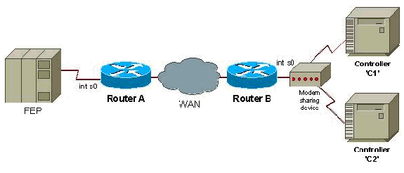
This document provides a sample configuration to configure Serial Tunnel (STUN) with Modem-Sharing Devices (MSD).
Prerequisites
Requirements
There are no specific requirements for this document.
Components Used
This document is not restricted to specific software and hardware versions.
Conventions
For more information on document conventions, refer to Cisco Technical Tips Conventions.
Configure
In this section, you are presented with the information to configure the features described in this document.
Note: To find additional information on the commands used in this document, use the Command Lookup Tool (registered customers only) .
Network Diagram
This document uses this network setup:

Configurations
This document uses these configurations:
| Router A |
|---|
stun peer-name 1.0.0.1 stun protocol-group 9 sdlc interface serial 0 encapsulation stun stun group 9 stun route address c1 tcp 5.0.0.1 local-ack stun route address c2 tcp 5.0.0.1 local-ack stun sdlc-role secondary sdlc address c1 sdlc address c2 interface loopback 0 ip address 1.0.0.1 255.255.255.0 |
| Router B |
|---|
stun peer-name 5.0.0.1 stun protocol-group 9 sdlc interface serial 0 encapsulation stun stun group 9 stun route address c1 tcp 1.0.0.1 local-ack stun route address c2 tcp 1.0.0.1 local-ack stun sdlc-role primary sdlc address c1 sdlc address c2 interface loopback 0 ip address 5.0.0.1 255.255.255.0 |
Note: Routers that attach to an MSD must use half duplex or must strap Data Terminal Ready (DTR) high, if the router serves as a DCE device. Also, IP routing and WAN configurations do not appear, for simplicity. For more details, refer to the document Configuring and Troubleshooting Serial Tunneling (STUN).
Verify
There is currently no verification procedure available for this configuration.
Troubleshoot
There is currently no specific troubleshooting information available for this configuration.
 Feedback