L4-L7 Route Peering with Transit Fabric - Configuration Walkthrough
Available Languages
Download Options
Bias-Free Language
The documentation set for this product strives to use bias-free language. For the purposes of this documentation set, bias-free is defined as language that does not imply discrimination based on age, disability, gender, racial identity, ethnic identity, sexual orientation, socioeconomic status, and intersectionality. Exceptions may be present in the documentation due to language that is hardcoded in the user interfaces of the product software, language used based on RFP documentation, or language that is used by a referenced third-party product. Learn more about how Cisco is using Inclusive Language.
Contents
Introduction
This document describes the configuration walkthrough of L4-L7 Service Graph with Route Peering, where both the consumer and the provider are external to the Application Centric Infrastructure (ACI) fabric.
Contributed by Zahid Hassan, Cisco Advanced Services Engineer.
Prerequisites
Requirements
Cisco recommends that you have knowledge of these topics:
- Static VLAN Pools that will be used for the encapsulation VLAN between the external devices and the ACI fabric
- External Physical and Routed Domains that will tie together the location (leaf node/path) of the external devices and the VLAN pool
- Layer 3 Connection to an Outside Network (L3Out)
The preceding Fabric Access and L3Out configurations steps are not covered in this document and have been assumed that these have already been completed.
Components Used
The information in this document is based on these software versions:
- Cisco Application Policy Infrastructure Controller (Cisco APIC) - 1.2(1m)
- Adaptive Security Appliance (ASA) Device Package - 1.2.4.8
- ASA 5585 - 9.5(1)
- Nexus 3064 - 6.0(2)U3(7)
The information in this document was created from the devices in a specific lab environment. All of the devices used in this document started with a cleared (default) configuration. If your network is live, make sure that you understand the potential impact of any command.
Background Information
Route Peering is a feature which enables a service appliance such as a load balancer or a firewall to advertise it’s reachability through the ACI fabric to all the way to an external network.
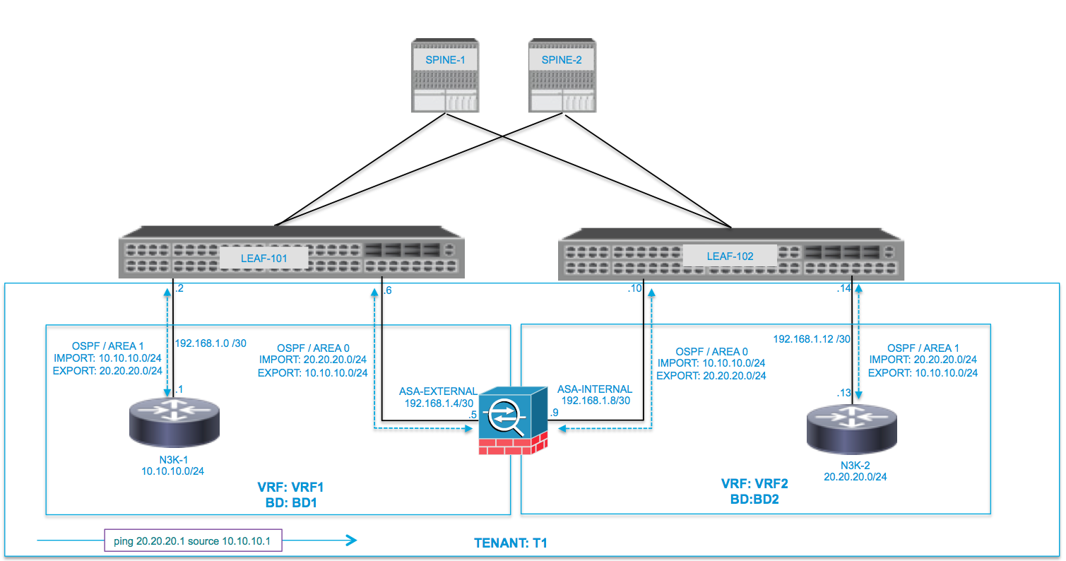
The use case presented here is a physical firewall which is deployed as a two-arm Service Graph, in between two L3Outs or external End Point Groups (EPGs). The Service Graph is associated with a contract between the external EPG on Leaf 101 (N3K-1) and the external EPG on Leaf 102 (N3K-2). The ACI fabric is providing a transit ervice for the routers (N3K-1 and N3K-2) and Route Peering is used, with Open Shortest Path First (OSPF) as the routing protocol, to exchange routes between the firewall and the ACI fabric.
Configure
Network Diagram
The following image shows how Route Peering works end-to-end:
Configure
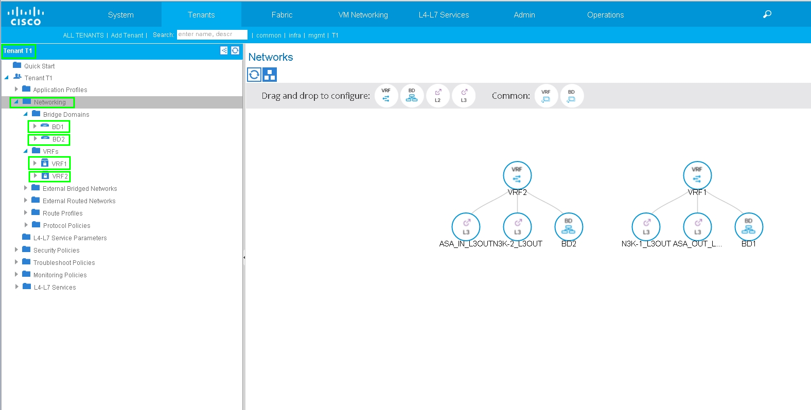
Step 1. Configure the Virtual Routing and Forwarding1 (VRF1), VRF2, Bridge Domain1 (BD1) and BD2. Associate BD1 to VRF1 and BD2 to VRF2, as shown in the image:
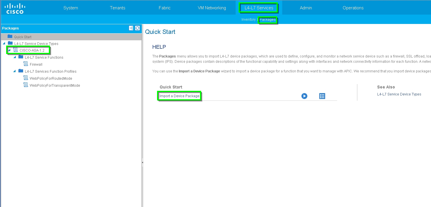
Step 2. Upload the ASA Device Package under L4-L7 Device, as shown in the image, :
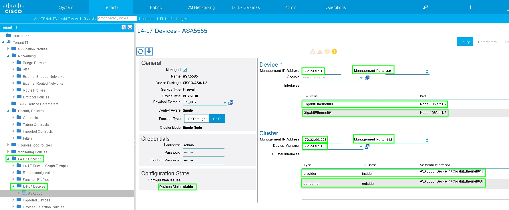
Configure L4-L7 Device for physical ASA 5585 (Routed), as shown in the image:
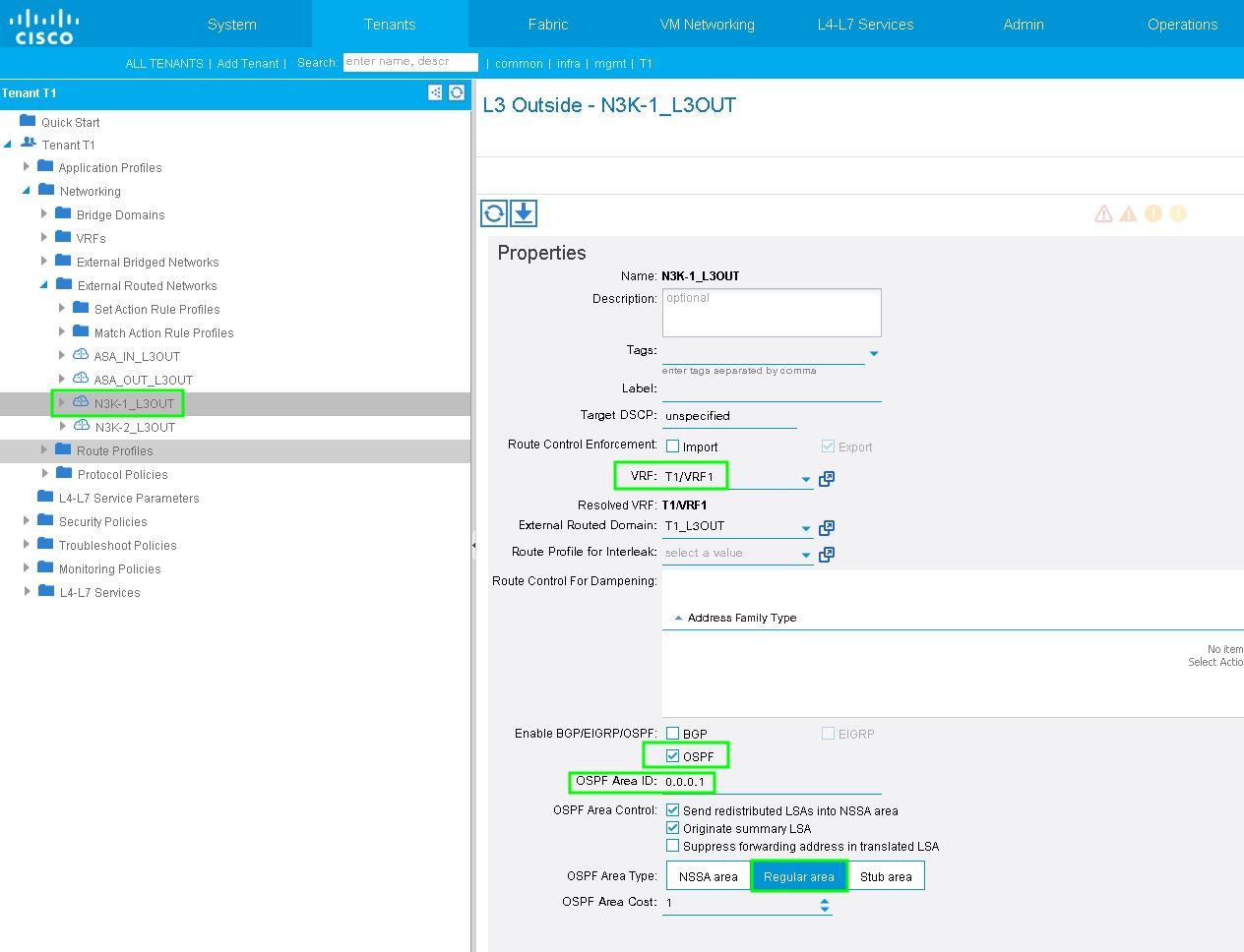
Step 3. Configure L3Out for N3K-1 and associate with BD1 and VRF1.
External routed network is used to specify the routing configuration in the ACI fabric for Route Peering, as shown in the image:
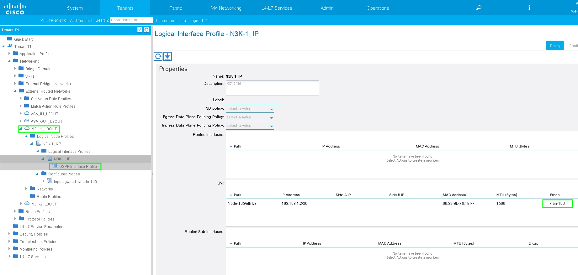
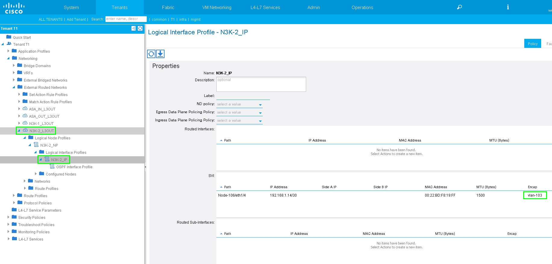
Note: All L3Out interfaces which are used for Route Peering, are required to be configured as a Switch Virtual Interface (SVI) with VLAN encap accordingly.
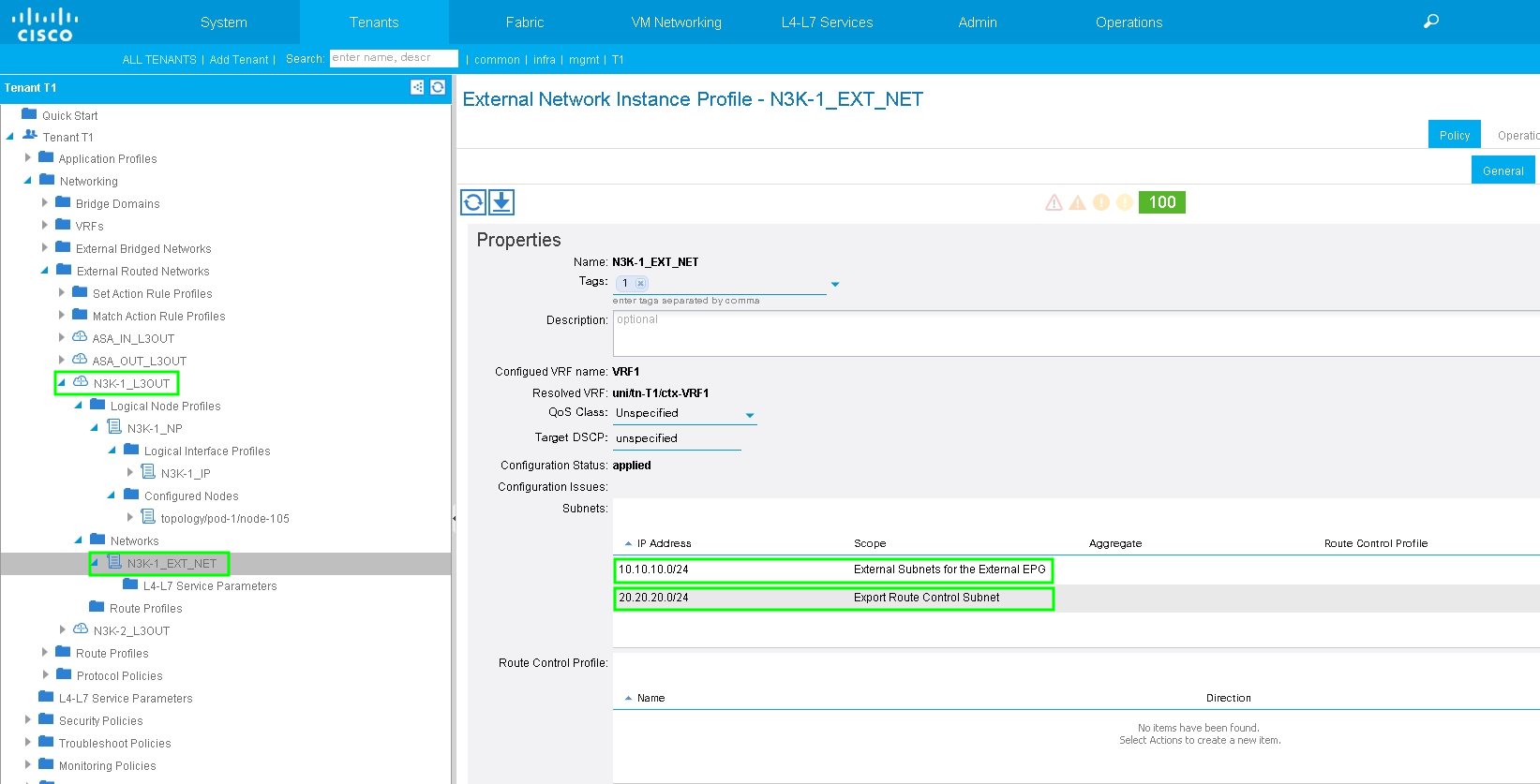
Configure Import/Export Route Control on Subnets for N3K-1 L3Out External EPG, as shown in the image:
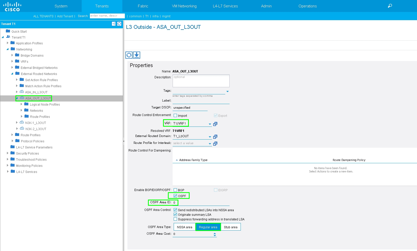
Configure L3Out for ASA-External Interface and associate with BD1 and VRF1, as shown in the image:
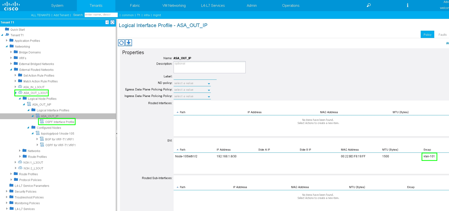
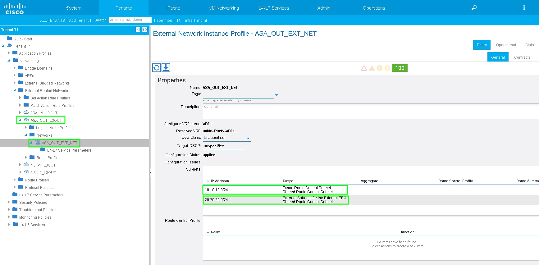
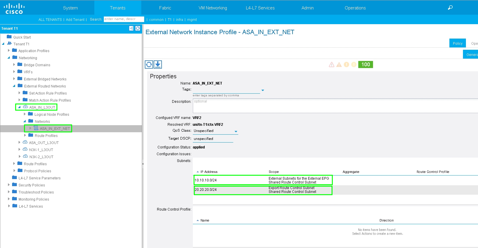
Configure Import/Export Route Control on Subnets for ASA-External L3Out External EPG, as shown in the image:
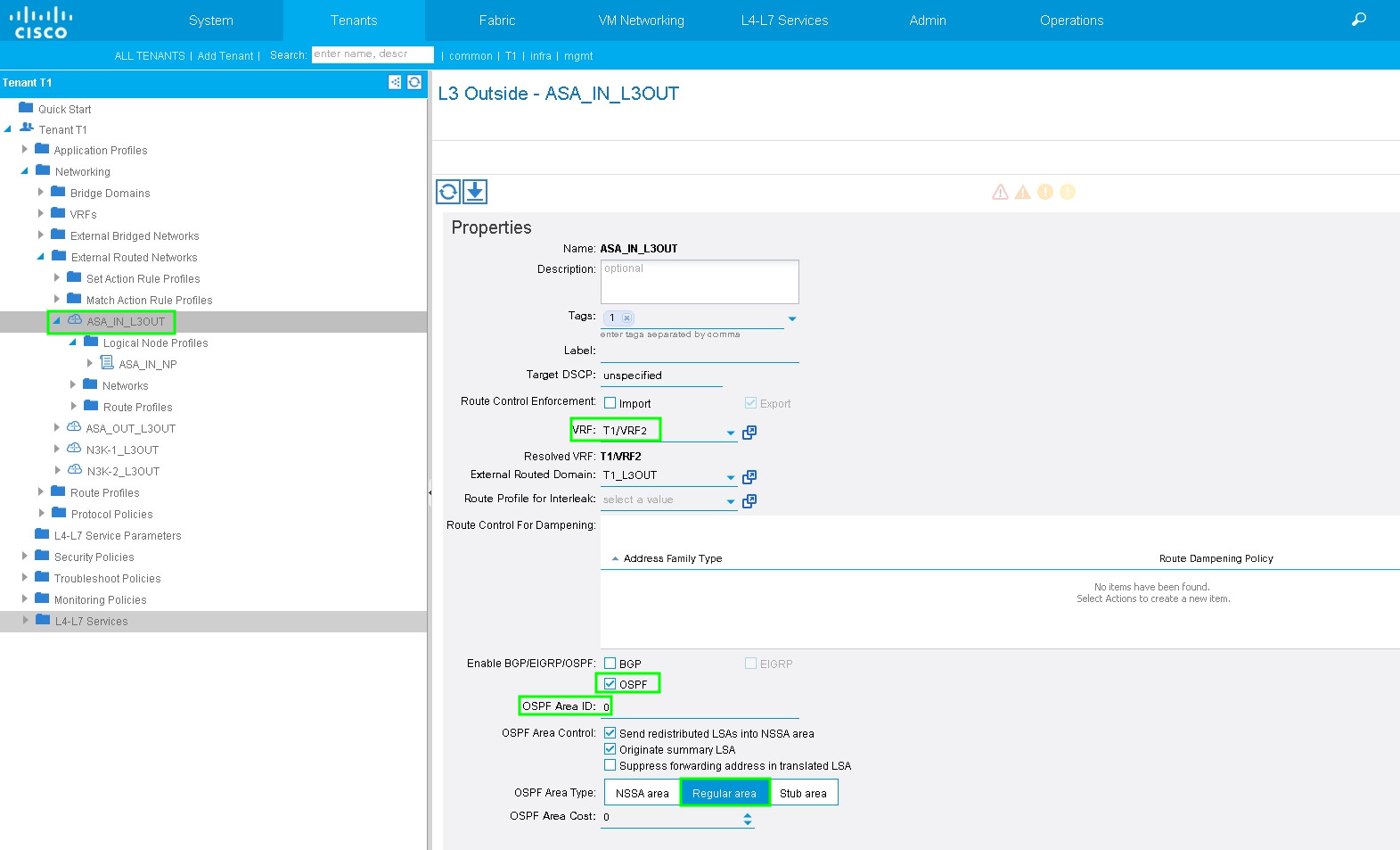
Configure L3out for ASA-Internal and associate with BD2 and VRF2, as shown in the image:
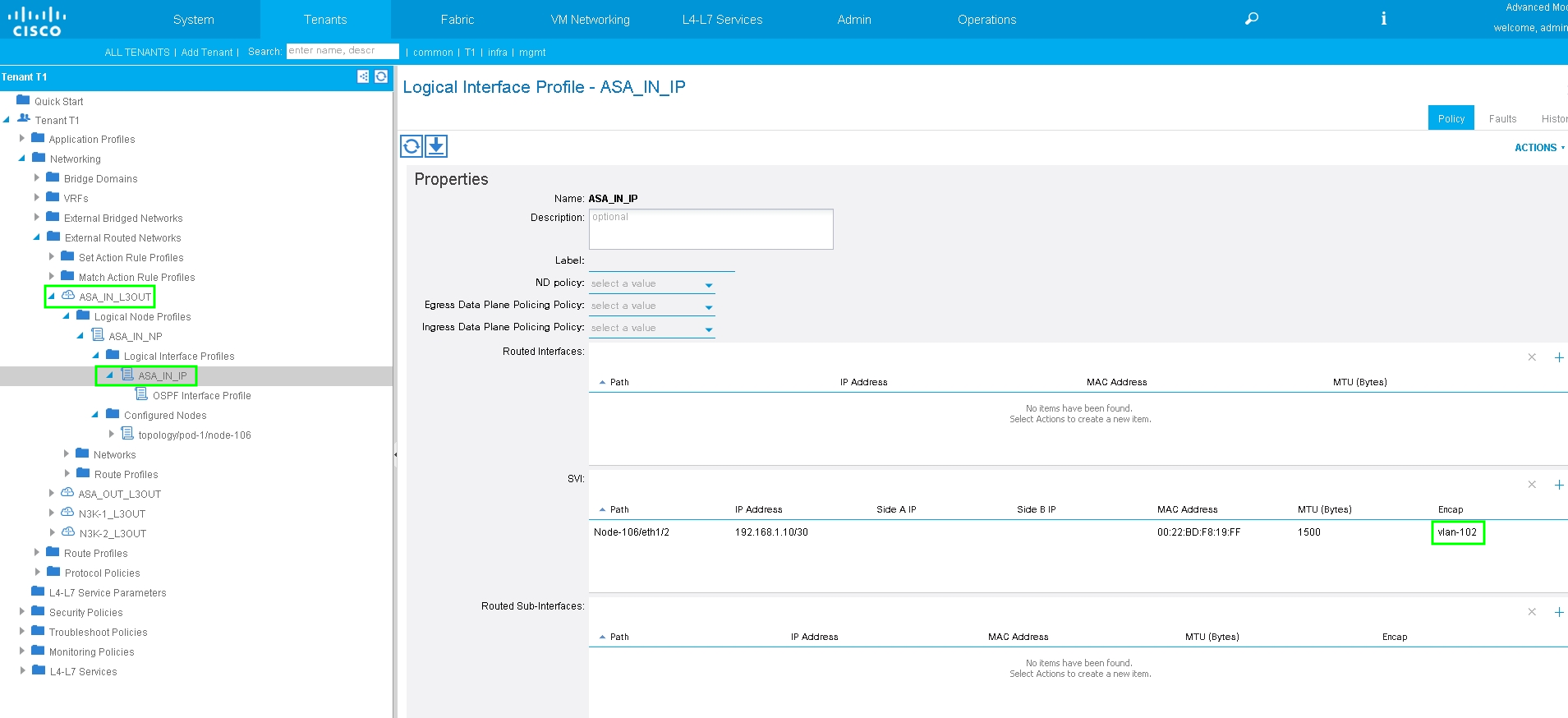
Configure Import/Export Route Control on Subnets for ASA-Internal L3Out External EPG, as shown in the image:
Configure L3Out for N3K-2 and associate with BD2 and VRF2, as shown in the image:

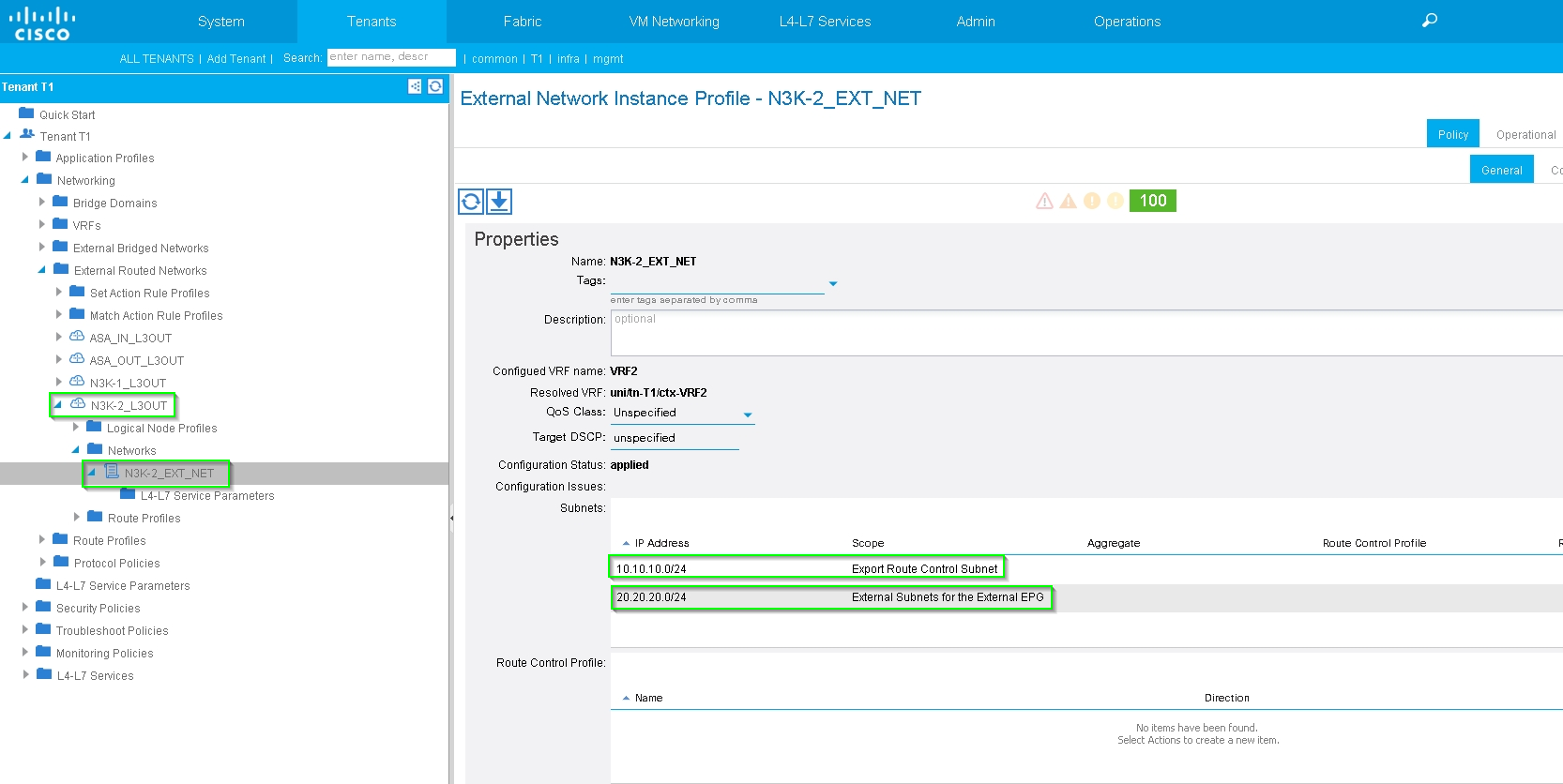
Configure Import/Export Route Control on Subnets for N3K-2 L3Out for External EPG, as shown in the image:
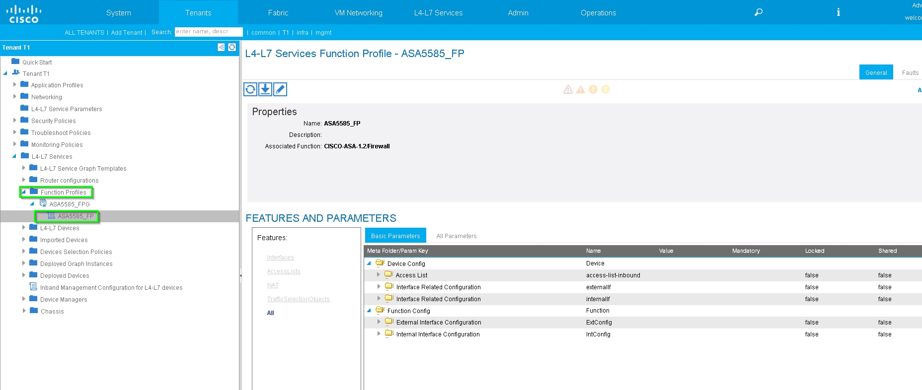
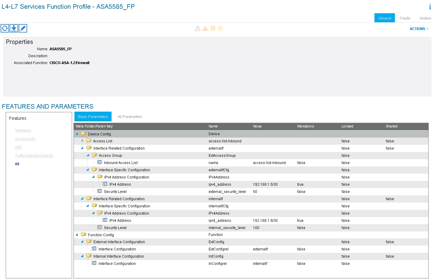
Step 4. Create Function Profile Group and configure Function Profile from existing template, as shown in the image:
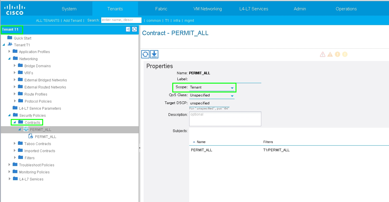
Step 5. Create a Contract and modify the Scope field to Tenant, as shown in the image:
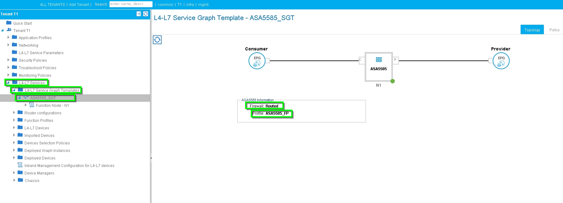
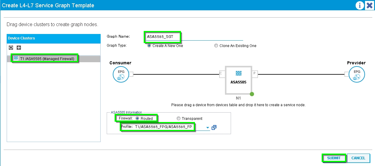
Step 6. As shown in the image, create L4-L7 Service Graph Template where Service Graph association involves the association of an external routed network policy and router configuration with a Device Selection Policy.
:
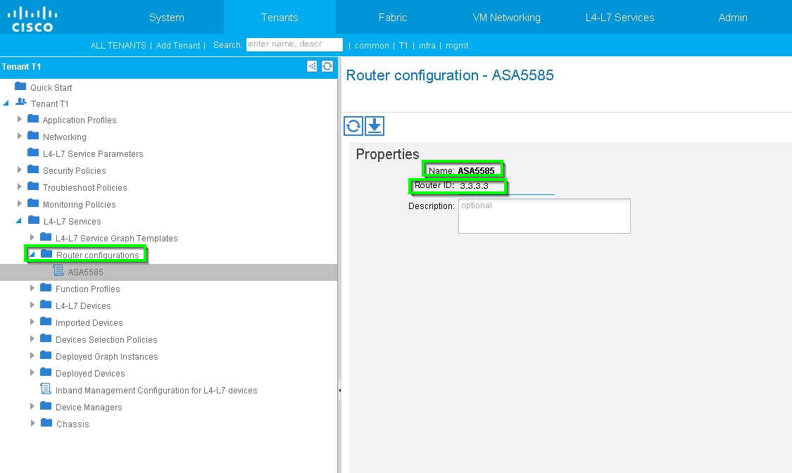
Router configuration to specify the Router ID that will be used on the Service Appliance (ASA 5585), as shown in the image:
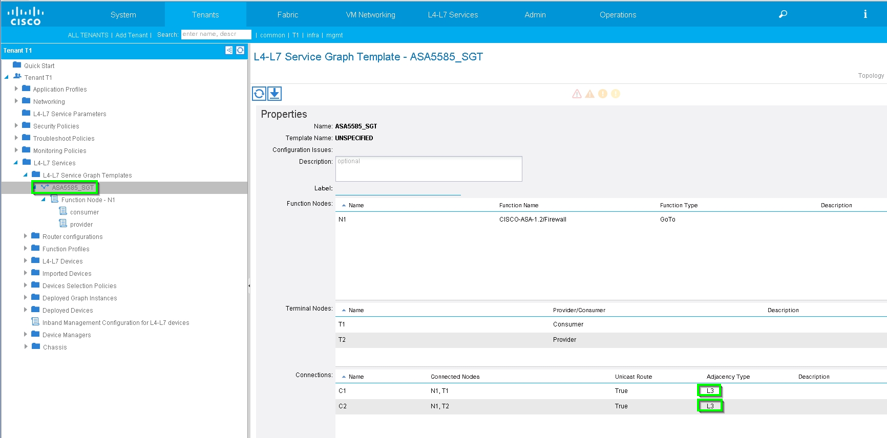
Change Adjacency Type from L2 to L3, as shown in the image:
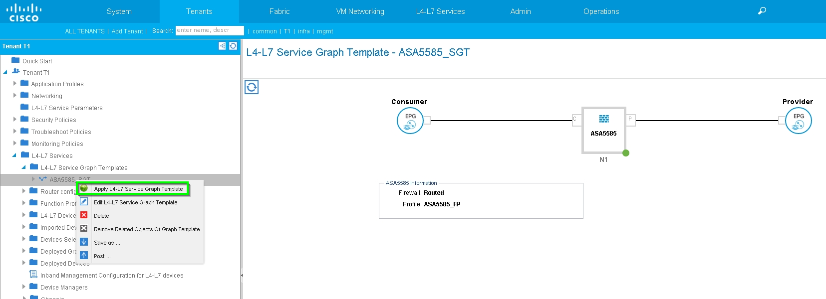
Apply Service Graph Template, as shown in the image:
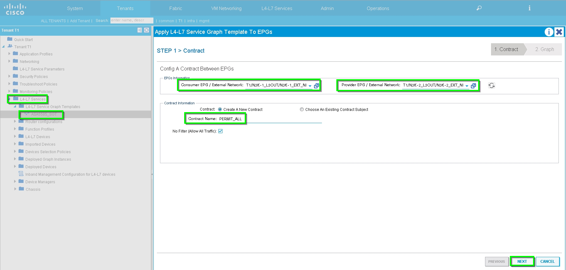
Attach the Service Graph to Contract, as shown in the image:
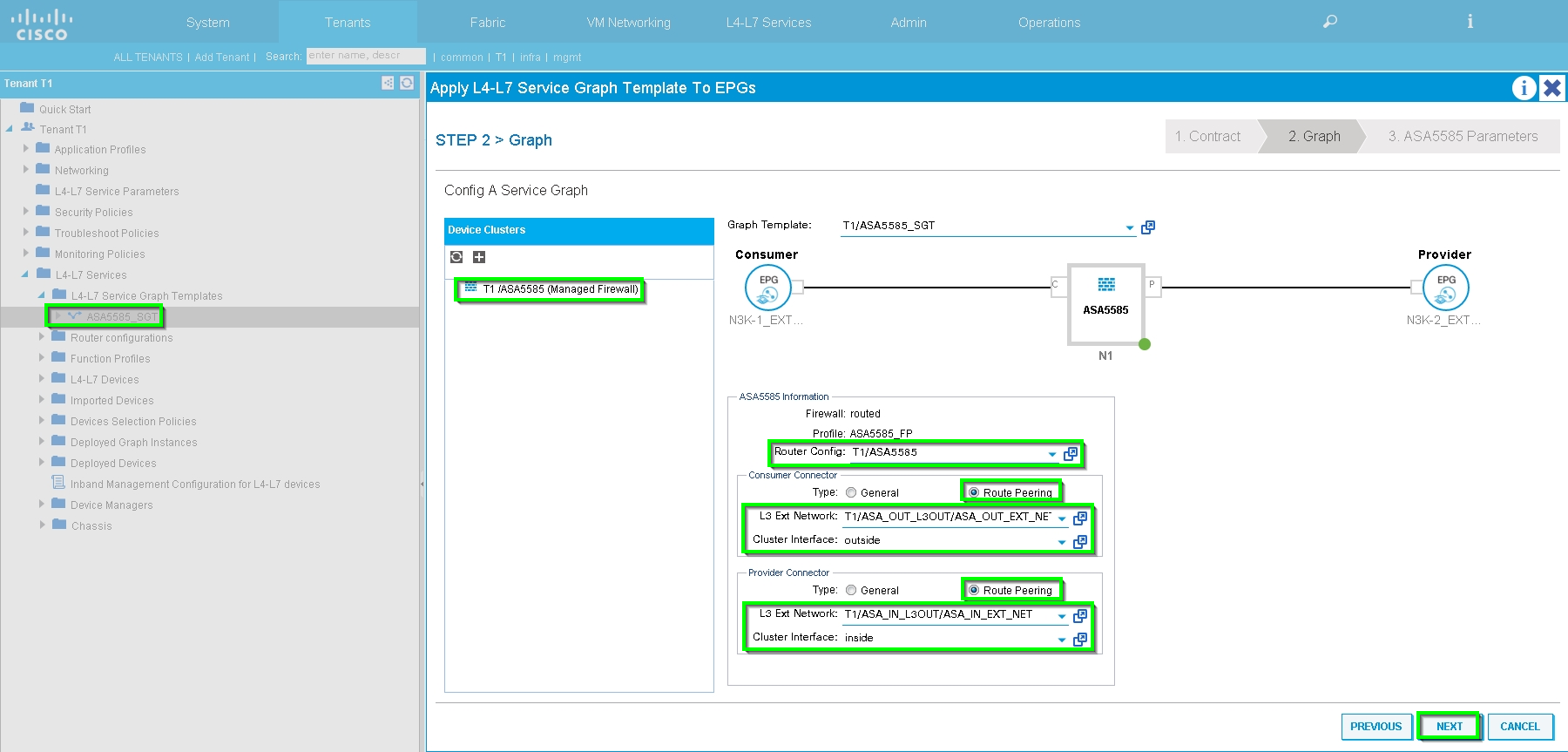
Add/Change L4-L7 Parameter if needed, as shown in the image:
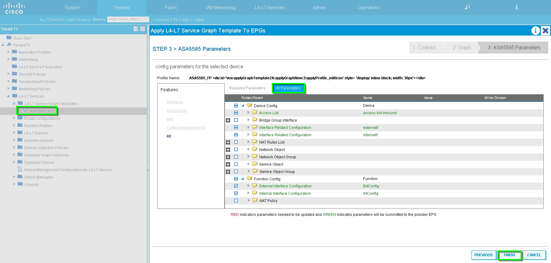
Step 7: Route-tag Policy, configure Route-tag Policy for VRF1 (Tag:100), as shown in the image:
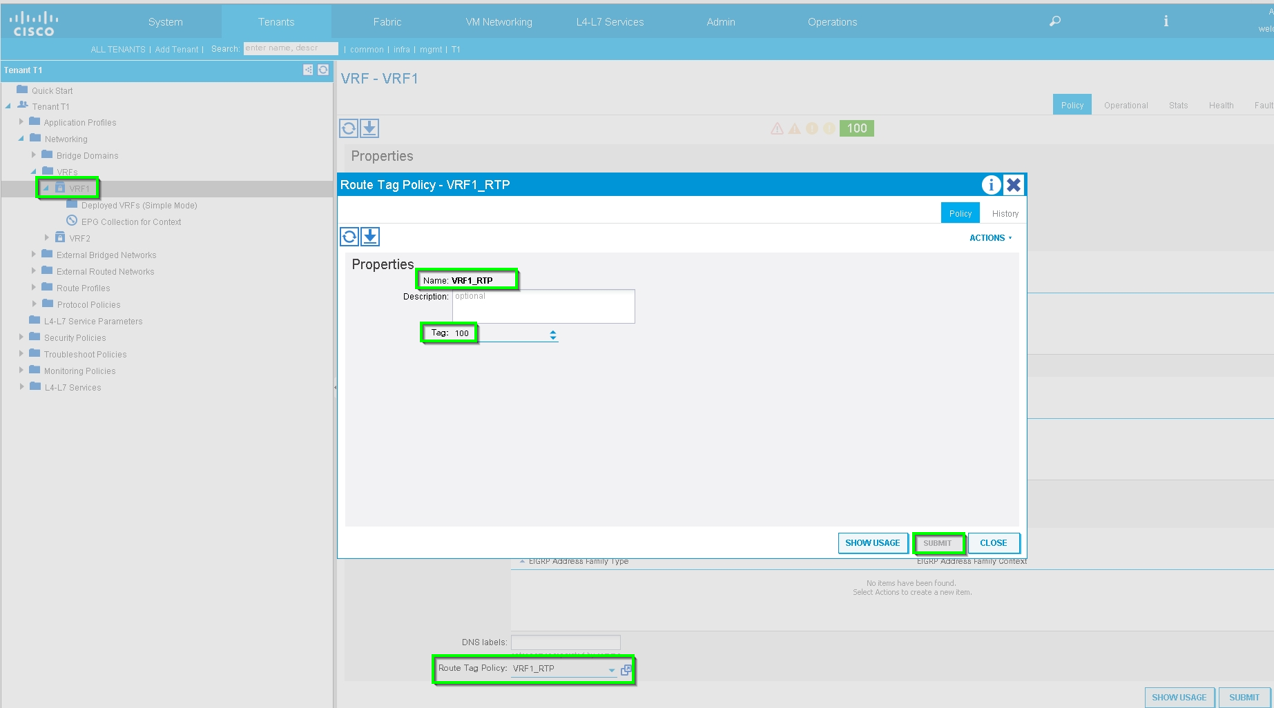
Configure Route-tag Policy for VRF2 (Tag:200), as shown in the image:
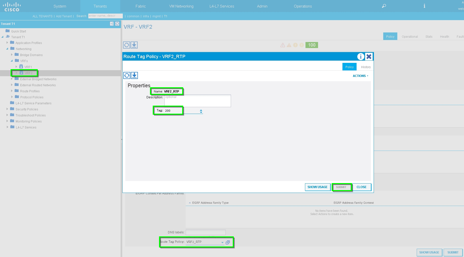
Step 8: Check the status and verify Device Selection Policy, as shown in the image:
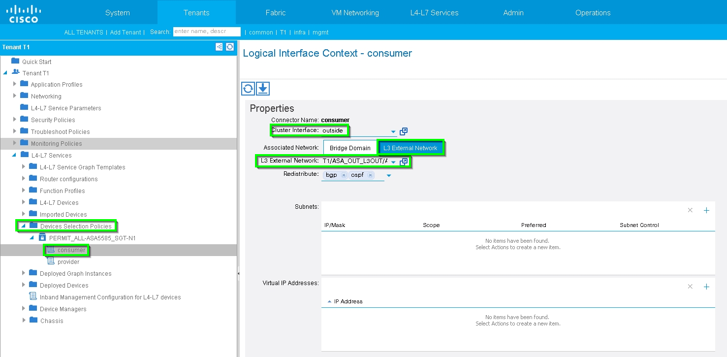
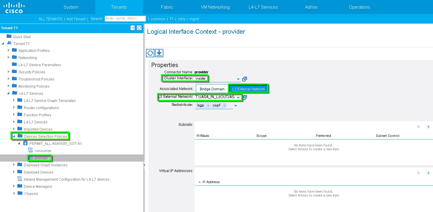
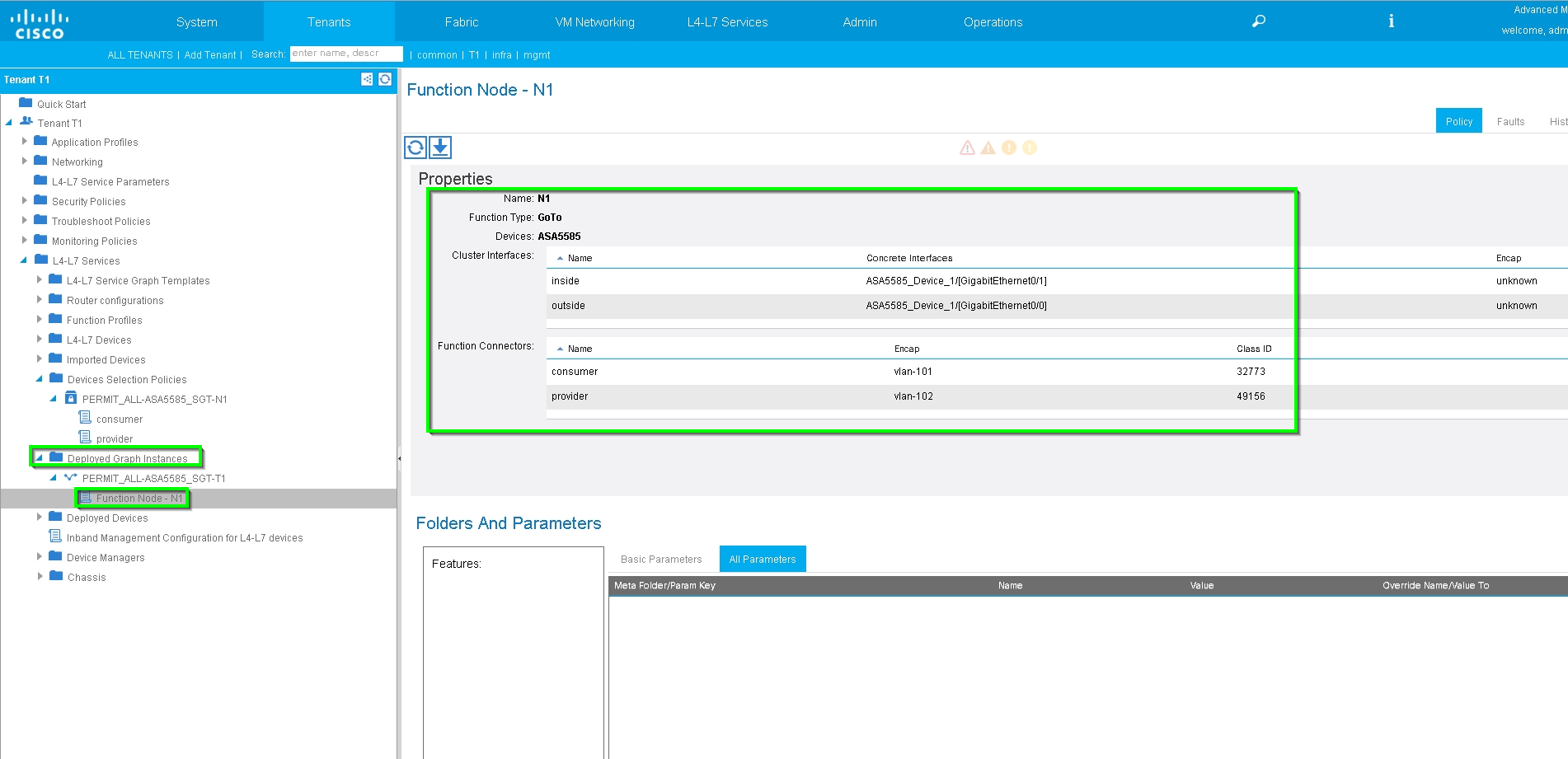
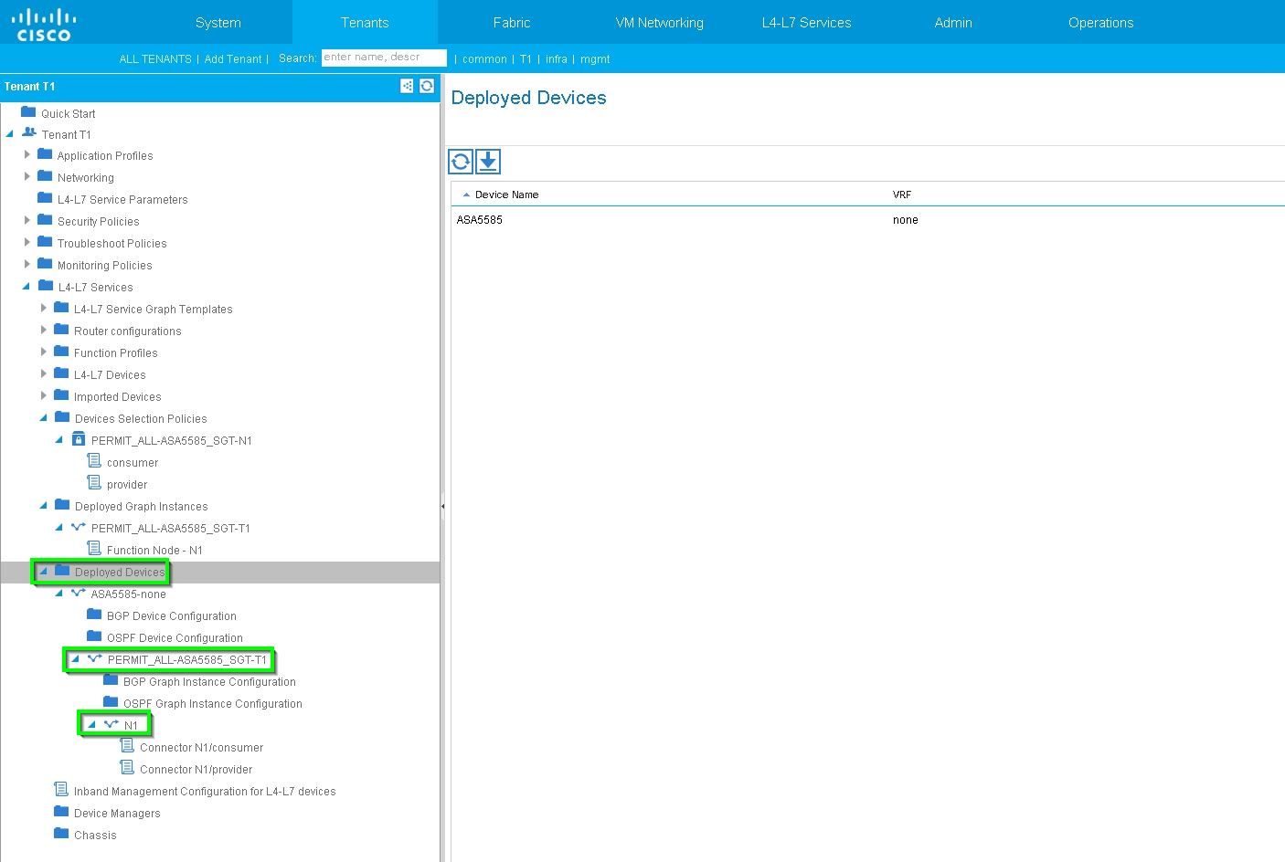
Verify Deployed Graph instance, as shown in the image:
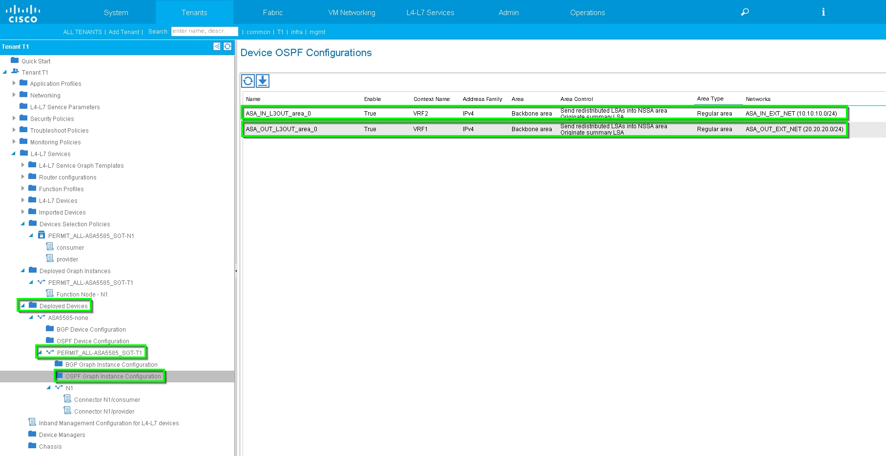
Verify and Troubleshoot
APIC configuration for Tenant:
apic1# sh running-config tenant T1
# Command: show running-config tenant T1
# Time: Thu Feb 25 16:05:14 2016
  tenant T1
    access-list PERMIT_ALL
      match ip
      exit
    contract PERMIT_ALL
      scope tenant
      subject PERMIT_ALL
        access-group PERMIT_ALL both
        l4l7 graph ASA5585_SGT
        exit
      exit
    vrf context VRF1
      exit
    vrf context VRF2
      exit
    l3out ASA_IN_L3OUT
      vrf member VRF2
      exit
    l3out ASA_OUT_L3OUT
      vrf member VRF1
      exit
    l3out N3K-1_L3OUT
      vrf member VRF1
      exit
    l3out N3K-2_L3OUT
      vrf member VRF2
      exit
    bridge-domain BD1
      vrf member VRF1
      exit
    bridge-domain BD2
      vrf member VRF2
      exit
    application AP1
      epg EPG1
        bridge-domain member BD1
        exit
      epg EPG2
        bridge-domain member BD2
        exit
      exit
    external-l3 epg ASA_IN_EXT_NET l3out ASA_IN_L3OUT
      vrf member VRF2
      match ip 10.10.10.0/24
      exit
    external-l3 epg ASA_OUT_EXT_NET l3out ASA_OUT_L3OUT
      vrf member VRF1
      match ip 20.20.20.0/24
      exit
    external-l3 epg N3K-1_EXT_NET l3out N3K-1_L3OUT
      vrf member VRF1
      match ip 10.10.10.0/24
      contract consumer PERMIT_ALL
      exit
    external-l3 epg N3K-2_EXT_NET l3out N3K-2_L3OUT
      vrf member VRF2
      match ip 20.20.20.0/24
      contract provider PERMIT_ALL
      exit
    interface bridge-domain BD1
      exit
    interface bridge-domain BD2
      exit
    l4l7 cluster name ASA5585 type physical vlan-domain T1_PHY service FW function go-to
      cluster-device ASA5585_Device_1
      cluster-interface inside
        member device ASA5585_Device_1 device-interface GigabitEthernet0/1
          interface ethernet 1/2 leaf 106
          exit
        exit
      cluster-interface outside
        member device ASA5585_Device_1 device-interface GigabitEthernet0/0
          interface ethernet 1/2 leaf 105
          exit
        exit
      exit
    l4l7 graph ASA5585_SGT contract PERMIT_ALL
      service N1 device-cluster-tenant T1 device-cluster ASA5585 mode FW_ROUTED
        connector consumer cluster-interface outside
          l4l7-peer tenant T1 out ASA_OUT_L3OUT epg ASA_OUT_EXT_NET redistribute bgp,ospf
          exit
        connector provider cluster-interface inside
          l4l7-peer tenant T1 out ASA_IN_L3OUT epg ASA_IN_EXT_NET redistribute bgp,ospf
          exit
        rtr-cfg ASA5585
        exit
      connection C1 terminal consumer service N1 connector consumer
      connection C2 terminal provider service N1 connector provider
      exit
    rtr-cfg ASA5585
      router-id 3.3.3.3
      exit
    exit
apic1#
[an error occurred while processing this directive]
Verify OSPF neighbor relationship and routing table on leaf 101:
leaf101# show ip ospf neighbors vrf T1:VRF1 OSPF Process ID default VRF T1:VRF1 Total number of neighbors: 2 Neighbor ID Pri State Up Time Address Interface 1.1.1.1 1 FULL/BDR 02:07:19 192.168.1.1 Vlan8 3.3.3.3 1 FULL/BDR 00:38:35 192.168.1.5 Vlan9[an error occurred while processing this directive]
leaf101# show ip route vrf T1:VRF1
IP Route Table for VRF "T1:VRF1"
'*' denotes best ucast next-hop
'**' denotes best mcast next-hop
'[x/y]' denotes [preference/metric]
'%<string>' in via output denotes VRF <string>
10.10.10.0/24, ubest/mbest: 1/0
*via 192.168.1.1, vlan8, [110/8], 01:59:50, ospf-default, intra
20.20.20.0/24, ubest/mbest: 1/0
*via 192.168.1.5, vlan9, [110/22], 00:30:20, ospf-default, inter
100.100.100.100/32, ubest/mbest: 2/0, attached, direct
*via 100.100.100.100, lo1, [1/0], 02:21:22, local, local
*via 100.100.100.100, lo1, [1/0], 02:21:22, direct
192.168.1.0/30, ubest/mbest: 1/0, attached, direct
*via 192.168.1.2, vlan8, [1/0], 02:35:53, direct
192.168.1.2/32, ubest/mbest: 1/0, attached
*via 192.168.1.2, vlan8, [1/0], 02:35:53, local, local
192.168.1.4/30, ubest/mbest: 1/0, attached, direct
*via 192.168.1.6, vlan9, [1/0], 02:20:53, direct
192.168.1.6/32, ubest/mbest: 1/0, attached
*via 192.168.1.6, vlan9, [1/0], 02:20:53, local, local
192.168.1.8/30, ubest/mbest: 1/0
*via 192.168.1.5, vlan9, [110/14], 00:30:20, ospf-default, intra
200.200.200.200/32, ubest/mbest: 1/0
*via 192.168.1.5, vlan9, [110/15], 00:30:20, ospf-default, intra
Verify OSPF neighbor relationship and routing table on leaf 102:
leaf102# show ip ospf neighbors vrf T1:VRF2
 OSPF Process ID default VRF T1:VRF2
 Total number of neighbors: 2
 Neighbor ID     Pri State            Up Time  Address         Interface
 3.3.3.3           1 FULL/BDR         00:37:07 192.168.1.9     Vlan14
 2.2.2.2           1 FULL/BDR         02:09:59 192.168.1.13    Vlan15


leaf102# show ip route vrf T1:VRF2
IP Route Table for VRF "T1:VRF2"
'*' denotes best ucast next-hop
'**' denotes best mcast next-hop
'[x/y]' denotes [preference/metric]
'%<string>' in via output denotes VRF <string>

10.10.10.0/24, ubest/mbest: 1/0
    *via 192.168.1.9, vlan14, [110/22], 00:35:22, ospf-default, inter
20.20.20.0/24, ubest/mbest: 1/0
    *via 192.168.1.13, vlan15, [110/8], 02:08:13, ospf-default, intra
192.168.1.4/30, ubest/mbest: 1/0
    *via 192.168.1.9, vlan14, [110/14], 00:35:22, ospf-default, intra
192.168.1.8/30, ubest/mbest: 1/0, attached, direct
    *via 192.168.1.10, vlan14, [1/0], 02:14:29, direct
192.168.1.10/32, ubest/mbest: 1/0, attached
    *via 192.168.1.10, vlan14, [1/0], 02:14:29, local, local
192.168.1.12/30, ubest/mbest: 1/0, attached, direct
    *via 192.168.1.14, vlan15, [1/0], 02:09:04, direct
192.168.1.14/32, ubest/mbest: 1/0, attached
    *via 192.168.1.14, vlan15, [1/0], 02:09:04, local, local
200.200.200.200/32, ubest/mbest: 2/0, attached, direct
    *via 200.200.200.200, lo4, [1/0], 02:10:02, local, local
    *via 200.200.200.200, lo4, [1/0], 02:10:02, direct
[an error occurred while processing this directive]
Verify configuration, OSPF neighbor relationship and routing table on ASA 5585:
ASA5585# sh run interface
!
interface GigabitEthernet0/0
 no nameif
 security-level 0
 no ip address
!
interface GigabitEthernet0/0.101
 nameif externalIf
 security-level 50
 ip address 192.168.1.5 255.255.255.252
!
interface GigabitEthernet0/1
 no nameif
 security-level 100
 no ip address
!
interface GigabitEthernet0/1.102
 nameif internalIf
 security-level 100
 ip address 192.168.1.9 255.255.255.252
!
interface Management0/0
 management-only
 nameif management
 security-level 0
 ip address 172.23.97.1 255.255.254.0


ASA5585# sh run router
router ospf 1
 router-id 3.3.3.3
 network 192.168.1.4 255.255.255.252 area 0
 network 192.168.1.8 255.255.255.252 area 0
 area 0
 log-adj-changes
!


ASA5585# sh ospf neighbor


Neighbor ID     Pri   State           Dead Time   Address         Interface
100.100.100.100   1   FULL/DR         0:00:38    192.168.1.6     externalIf
200.200.200.200   1   FULL/DR         0:00:33    192.168.1.10    internalIf


ASA5585# sh route ospf


Routing Table: T1
Codes: L - local, C - connected, S - static, R - RIP, M - mobile, B - BGP
       D - EIGRP, EX - EIGRP external, O - OSPF, IA - OSPF inter area
       N1 - OSPF NSSA external type 1, N2 - OSPF NSSA external type 2
       E1 - OSPF external type 1, E2 - OSPF external type 2
       i - IS-IS, su - IS-IS summary, L1 - IS-IS level-1, L2 - IS-IS level-2
       ia - IS-IS inter area, * - candidate default, U - per-user static route
       o - ODR, P - periodic downloaded static route, + - replicated route
Gateway of last resort is not set

O IA     10.10.10.0 255.255.255.0
           [110/18] via 192.168.1.6, 00:22:57, externalIf
O IA     20.20.20.0 255.255.255.0
           [110/18] via 192.168.1.10, 00:22:47, internalIf
O        200.200.200.200 255.255.255.255
           [110/11] via 192.168.1.10, 00:22:47, internalIf


ASA5585# sh access-list
access-list cached ACL log flows: total 0, denied 0 (deny-flow-max 4096)
            alert-interval 300
access-list access-list-inbound; 3 elements; name hash: 0xcb5bd6c7
access-list access-list-inbound line 1 extended permit tcp any any eq www (hitcnt=0) 0xc873a747
access-list access-list-inbound line 2 extended permit tcp any any eq https (hitcnt=0) 0x48bedbdd
access-list access-list-inbound line 3 extended permit icmp any any (hitcnt=6) 0xe4b5a75d[an error occurred while processing this directive]
Verify configuration, OSPF neighbor relationship and routing table on N3K-1:
N3K-1# sh run ospf

!Command: show running-config ospf
!Time: Thu Feb 25 15:40:55 2016

version 6.0(2)U3(7)
feature ospf

router ospf 1
  router-id 1.1.1.1

interface Ethernet1/21
  ip router ospf 1 area 0.0.0.1

interface Ethernet1/47
  ip router ospf 1 area 0.0.0.1


N3K-1# sh ip ospf neighbors
 OSPF Process ID 1 VRF default
 Total number of neighbors: 1
 Neighbor ID     Pri State            Up Time  Address         Interface
 100.100.100.100   1 FULL/DR          01:36:24 192.168.1.2     Eth1/47


N3K-1# sh ip ospf route
 OSPF Process ID 1 VRF default, Routing Table
  (D) denotes route is directly attached      (R) denotes route is in RIB
10.10.10.0/24 (intra)(D) area 0.0.0.1
     via 10.10.10.0/Eth1/21* , cost 4
20.20.20.0/24 (inter)(R) area 0.0.0.1
     via 192.168.1.2/Eth1/47 , cost 62
100.100.100.100/32 (intra)(R) area 0.0.0.1
     via 192.168.1.2/Eth1/47 , cost 41
192.168.1.0/30 (intra)(D) area 0.0.0.1
     via 192.168.1.1/Eth1/47* , cost 40
[an error occurred while processing this directive]
Verify configuration, OSPF neighbor relationship and routing table on N3K-2:
N3K-2# sh run ospf

!Command: show running-config ospf
!Time: Thu Feb 25 15:44:47 2016

version 6.0(2)U3(7)
feature ospf

router ospf 1
  router-id 2.2.2.2

interface loopback0
  ip ospf network point-to-point
  ip router ospf 1 area 0.0.0.0

interface Ethernet1/21
  ip router ospf 1 area 0.0.0.1

interface Ethernet1/47
  ip router ospf 1 area 0.0.0.1


N3K-2# sh ip ospf neighbors
 OSPF Process ID 1 VRF default
 Total number of neighbors: 1
 Neighbor ID     Pri State            Up Time  Address         Interface
 200.200.200.200   1 FULL/DR          01:43:50 192.168.1.14    Eth1/47

N3K-2# sh ip ospf route
 OSPF Process ID 1 VRF default, Routing Table
  (D) denotes route is directly attached      (R) denotes route is in RIB
2.2.2.0/30 (intra)(D) area 0.0.0.0
     via 2.2.2.0/Lo0* , cost 1
10.10.10.0/24 (inter)(R) area 0.0.0.1
     via 192.168.1.14/Eth1/47 , cost 62
20.20.20.0/24 (intra)(D) area 0.0.0.1
     via 20.20.20.0/Eth1/21* , cost 4
192.168.1.12/30 (intra)(D) area 0.0.0.1
     via 192.168.1.13/Eth1/47* , cost 40
[an error occurred while processing this directive]
Verify contract filter rules on leaf and the packet hit counts:.
leaf101# show system internal policy-mgr stats Requested Rule Statistics [CUT] Rule (4107) DN (sys/actrl/scope-3112964/rule-3112964-s-32773-d-49158-f-33) Ingress: 1316, Egress: 0, Pkts: 0 RevPkts: 0 Rule (4108) DN (sys/actrl/scope-3112964/rule-3112964-s-49158-d-32773-f-33) Ingress: 1317, Egress: 0, Pkts: 0 RevPkts: 0 leaf101# show system internal policy-mgr stats Requested Rule Statistics [CUT] Rule (4107) DN (sys/actrl/scope-3112964/rule-3112964-s-32773-d-49158-f-33) Ingress: 2317, Egress: 0, Pkts: 0 RevPkts: 0 Rule (4108) DN (sys/actrl/scope-3112964/rule-3112964-s-49158-d-32773-f-33) Ingress: 2317, Egress: 0, Pkts: 0 RevPkts: 0[an error occurred while processing this directive]
leaf102# show system internal policy-mgr stats Requested Rule Statistics [CUT] Rule (4103) DN (sys/actrl/scope-2752520/rule-2752520-s-49156-d-6019-f-default) Ingress: 3394, Egress: 0, Pkts: 0 RevPkts: 0 Rule (4104) DN (sys/actrl/scope-2752520/rule-2752520-s-6019-d-49156-f-default) Ingress: 3394, Egress: 0, Pkts: 0 RevPkts: 0 [CUT] leaf102# show system internal policy-mgr stats Requested Rule Statistics [CUT] Rule (4103) DN (sys/actrl/scope-2752520/rule-2752520-s-49156-d-6019-f-default) Ingress: 4392, Egress: 0, Pkts: 0 RevPkts: 0 Rule (4104) DN (sys/actrl/scope-2752520/rule-2752520-s-6019-d-49156-f-default) Ingress: 4392, Egress: 0, Pkts: 0 RevPkts: 0 [CUT]
Reachability test between N3K-1 and N3K-2:
    N3K-1# ping 20.20.20.1 source 10.10.10.1
PING 20.20.20.1 (20.20.20.1) from 10.10.10.1: 56 data bytes
64 bytes from 20.20.20.1: icmp_seq=0 ttl=250 time=2.098 ms
64 bytes from 20.20.20.1: icmp_seq=1 ttl=250 time=0.922 ms
64 bytes from 20.20.20.1: icmp_seq=2 ttl=250 time=0.926 ms
64 bytes from 20.20.20.1: icmp_seq=3 ttl=250 time=0.893 ms
64 bytes from 20.20.20.1: icmp_seq=4 ttl=250 time=0.941 ms

--- 20.20.20.1 ping statistics ---
5 packets transmitted, 5 packets received, 0.00% packet loss
round-trip min/avg/max = 0.893/1.156/2.098 ms


N3K-2# ping 10.10.10.1 source 20.20.20.1
PING 10.10.10.1 (10.10.10.1) from 20.20.20.1: 56 data bytes
64 bytes from 10.10.10.1: icmp_seq=0 ttl=250 time=2.075 ms
64 bytes from 10.10.10.1: icmp_seq=1 ttl=250 time=0.915 ms
64 bytes from 10.10.10.1: icmp_seq=2 ttl=250 time=0.888 ms
64 bytes from 10.10.10.1: icmp_seq=3 ttl=250 time=1.747 ms
64 bytes from 10.10.10.1: icmp_seq=4 ttl=250 time=0.828 ms

--- 10.10.10.1 ping statistics ---
5 packets transmitted, 5 packets received, 0.00% packet loss
round-trip min/avg/max = 0.828/1.29/2.075 ms
[an error occurred while processing this directive]
Attached is the XML configuration file for the Tenant and the ASA Function Profile, used for this demonstration.
Contributed by Cisco Engineers
- Zahid HassanCisco Advanced Services Engineer
Contact Cisco
- Open a Support Case

- (Requires a Cisco Service Contract)

 Feedback