uBR-MC5x20u-d and uBR-MC2x8u Line Card Handling Recommendations
Available Languages
Contents
Introduction
Based on observations from Cable multiple service operators (MSOs), as well as additional internal investigations and discussions, Cisco has identified a few areas which are suspected to contribute to electrostatic discharge (ESD) in the case of the uBR-MC5x20u-d and uBR-MC2x8u. ESD is the release of stored static electricity that can damage electrical circuitry. Static electricity is often stored in your body, and discharged when you come in contact with an object with a different potential.
Prerequisites
Requirements
Cisco recommends that you have knowledge of these topics:
-
Broadband Cable Industry
-
Cisco IOS®
-
Radio Frequency (RF) Cabling
Components Used
The information in this document is based on Cisco Universal Broadband Routers with Cisco IOS Software Releases 12.2(15)BC or later.
The information in this document was created from the devices in a specific lab environment. All of the devices used in this document started with a cleared (default) configuration. If your network is live, make sure that you understand the potential impact of any command.
Related Products
This configuration can also be used with these hardware versions:
-
uBR-MC5x20u-d card
-
uBR-MC2x8u card
Conventions
Refer to Cisco Technical Tips Conventions for more information on document conventions.
Materials That Generate Static Electrics
Almost any material can generate static electricity. The ability to store or dissipate the charge depends on the type of material. When you deal with static electricity, the types of materials involved must be considered. Materials are divided into two basic classifications: conductors and insulators.
Conductors
Conductors can generate charges that jump to ESD-sensitive components and assemblies. Within a conductor, electrons move freely throughout the entire body. Therefore, when an ungrounded conductor becomes charged, the entire volume of the conductive body assumes a charge of the same potential and polarity. Because the ground is virtually an infinite source and receptacle for electrons, you can connect a charged conductor to the earth ground in order to neutralize it. If a conductor is positively charged and connected to the ground, the required quantity of electrons flow from the ground to the conductor until the conductor becomes neutral. In the reverse, if the conductor is negatively charged and then connected to the ground, the excess electrons flow to the ground until the conductor becomes neutral. These are examples of conductors:
Figure A: Examples of Conductors 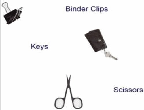
Insulators
Insulators hold charges. These stored charges can be discharged to ESD-sensitive components and assemblies. Within an insulator, the flow of electrons is very limited. Because of this, an insulator can retain several static charges of different potentials and polarities at various areas on its surface.
Figure B: Electron Charge Differences of Insulators 
Although insulators react differently to static electricity, they can be neutralized by simple grounding techniques when made conductive. These are examples of insulators:
Figure C: Examples of Insulators 
Suspect Areas
-
Mini-coax cables that are connected on the uBR line card, but are not connected anywhere on the other (F-connector) side, potentially pick up ESD through the exposed center conductor. This occurs when the cables touch things such as plastic bags, a non-ESD floor, sheaths of other cables, human clothing or Human Body Potential (HBP).
-
Portable power meters that can potentially hold charge and, if the center conductor of the F mini-coax happens to come close to or into direct contact with the connector thread on the meter, this can cause a problem.
-
The Upconverter (UPx) is most sensitive when powered up. Therefore, it is suggested to keep it powered down initially during the install.
Differences With Various MSOs
Cisco has identified differences in the way MSOs deploy cable line cards that can help minimize or eliminate ESD risk.
-
Prudent MSOs remove the cables completely from their plastic bags, prepare them, and connect them up to the cable plant in rapid succession, with little delay. The MSOs install each cable completely before they move on to the next cable.
-
Some MSOs do not perform any power output measurements directly on the line cards, but rather use -20dB points further down the cable plant. This is after they have passed through a number of splitters and combiners, which attenuate the signal even further.
ESD Wrist Strap Instructions
It is extremely important to always use an ESD wrist strap whenever you install the uBR-MC5x20u-d and uBR-MC2x8u cards into the Cisco cable modem termination system (CMTS). This practice is encouraged when you work with any Cisco equipment. The wrist strap must make good contact with your skin at one end and with the chassis at the other end in order to work correctly. Make sure that all equipment is properly grounded.
 Warning: Before you access the CMTS chassis interior, turn off power to the chassis and unplug the power cord. Use extreme caution around the chassis because potentially harmful voltages are present.
Note: Once you confirm that the equipment is properly grounded and the power is off, you can plug in the power cord to make it grounded by the plug.
 Warning: The wrist strap is intended for static control only. It does not reduce or increase your risk of receiving an electric shock from electrical equipment. Use the same precautions you would use without a wrist strap.
These steps describe how to use the wrist strap correctly:
-
Remove the wrist strap from its envelope. As shown in Figure 1, one end terminates with a patch of copper foil (equipment end), and the other end has an area with the black metal strip exposed (wrist end).
Figure 1: ESD Wrist Strap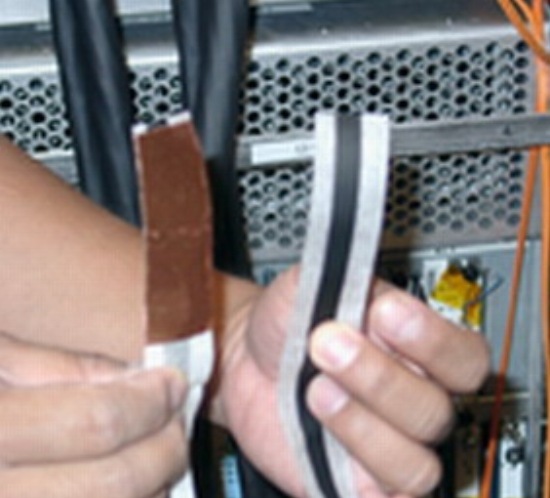
-
Unwrap the wrist end to expose the adhesive. Place the exposed metal strip (wrist end) against your skin, and wrap the strip firmly around your wrist for a snug fit (see Figure 2).
Figure 2: Wrist Strap Attached to the Wrist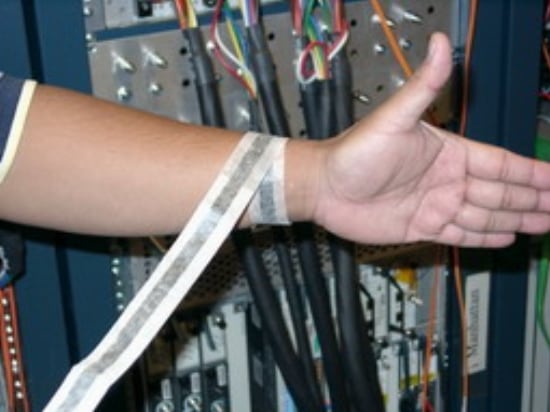
-
Unroll the rest of the strap, and peel the liner from the copper foil patch at the opposite end (equipment end).
-
Attach the copper foil patch to a flat, unpainted surface on the uBR chassis by pressing it firmly onto the surface. Cisco recommends that you attach it to the inside bottom of the chassis, the rear panel (inside or outside), or the chassis bottom. Do not make contact with any connectors or line cards (see Figure 3).
Figure 3: Wrist Strap Attached to the uBR10k Chassis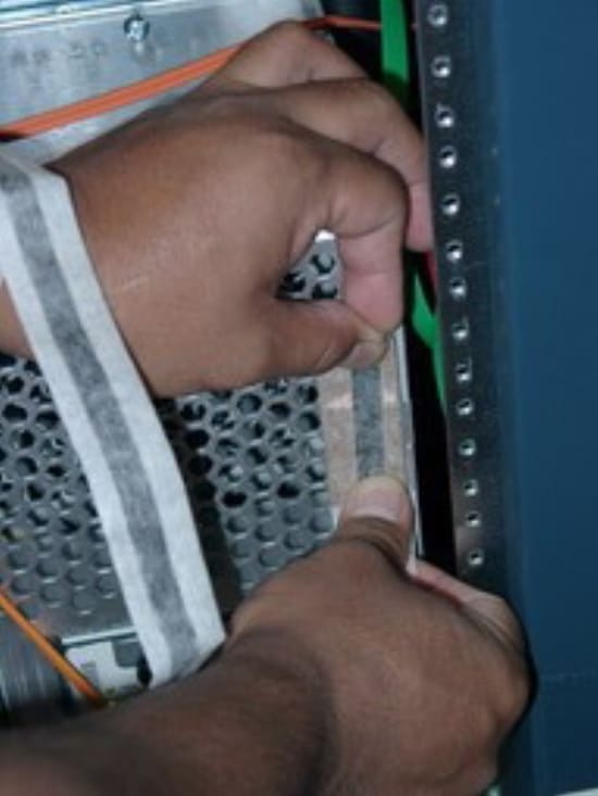
High-Level Precautions
The high-level precautions center around these 3 areas:
-
Keep power off—Keep power to the line card off during high-risk times. For example, every time you connect and disconnect anything to the line card, either directly, or via the cables themselves.
-
Terminate all cables—Minimize potential for cables to pick up ESD by putting termination caps on them all the time, other than for the time when they are actively used to measure the output.
-
Protect with attenuators—Have -30dB attenuators constantly on the cables at all times, so that if ESD gets through during high-risk times, its effect is attenuated by the time it reaches the cable and the line card UPx.
Cabling and Power Output Testing
More specifically, the recommended procedures are provided in this section.
Preparation
This additional material needs to be procured ahead of the test procedure:
-
75-ohm terminators for the F-connectors
-
Quantity—Five terminators should suffice for the procedure outlined in this section. In general, you need as many terminators as you have cables that you would like to hook up to the uBR10K simultaneously.
-
-
-30dB attenuators
-
Quantity—Five attenuators should suffice for a testing environment.
-
Example type—Viewsonics makes decent F-connector type in-line attenuators.
-
Line Card Insertion and CMTS Initialization
Complete these steps:
-
Start with the CMTS powered down.
-
Install the 5x20 line card (see Figure 4).
Do NOT yet connect any cabling to them.
Figure 4: Install the uBR-MC5x20u-d Card to the uBR10k Chassis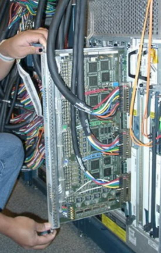
-
Power up the CMTS.
-
Issue the cable power off (slot/subslot) command for each line card in order to power down all line cards.
This command turns the power off for that particular subslot/line card.
Note: It is NOT sufficient to just shut the interface down. The entire line card needs to be powered down with this command. As a general note, all line cards must be powered down at all times, apart from the one under the power test. For the one under test, it must only be powered up when an actual power measurement is performed. It needs to be turned off prior to connecting any cables. Also the power must be turned off prior to disconnecting any cables.
Downstream Cable Handling
Complete these steps:
-
Remove each 5-pack from the plastic bags completely.
-
Add a -30dB attenuator to each one of the 5 downstreams (see Figure 6).
Figure 6: Adding the Attenuator to the Downstream Cable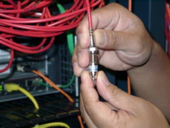
-
Add a terminator to each of the 5 attenuators (see Figure 7).
Figure 7: Add the Terminator to the Downstream Cable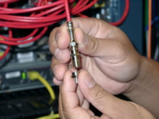
-
Add the headers on the dense side (see Figure 5).
Figure 5: Connect the Header to the uBR-MC5x20 Card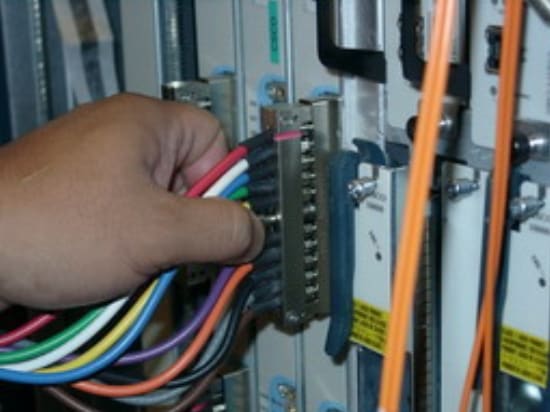
At the end of this, each of the 5 cables on the 5-pack has this setup: terminator-----attenuator-----F-connector (see Figure 7).
Test Each New Line Card
Complete these steps:
-
Start with the first line card to test.
-
Issue the cable power off (slot/subslot) command in order to make sure the card to be tested is powered down.
-
Connect the cable bundle to the downstream of the line card to be tested.
Test Each Downstream on a Line Card
Note: Have measurements taken at the center frequency at two RF level settings (55 and 61 dBmV), as well as a series of measurements taken at an RF level setting of 58 dBmV over 57, 363, 621 and 855 MHz center frequencies. Measurements should be done under controlled laboratory conditions with instruments and cards in a stable warmed-up state. Use a vector signal analyzer, HP8591C, AT2500, or all three of these if possible, in order to measure all downstream ports of each card.
Complete these steps:
-
Start with the downstream you want to test.
-
Make sure the card that the downstream that is on is powered down.
Try to ground the power meter female F-connector threads.
-
Remove the 75-ohm termination from the downstream to be tested, but NOT its attenuator.
Leave the attenuators and terminations for the other downstreams intact.
-
Connect the power meter to the downstream to be tested.
-
Issue the cab power on (slot/subslot) command in order to power up the line card.
-
Wait for the line card to be ready.
Perform the Power Measurement for that Downstream
Refer to Obtain Power Measurements of a DOCSIS Downstream Signal Using a Spectrum Analyzer for more information.
Complete these steps:
-
Power the line card off when the power measurement is finished, but BEFORE you disconnect anything.
-
Disconnect the power meter from the attenuator.
Note: Leave the attenuator connected to the dense cable, NOT the power meter.
-
Replace the 75-ohm termination at the end of the attenuator.
-
Advance to the next downstream on the line card and repeat the steps from the Test Each Downstream on a Line Card section and the steps in this section in order to test all 5 downstreams.
Note: Allow measurements to have a variance of 2-3dB.
After All Five Downstreams are Tested
Complete these steps:
-
Make sure all line cards are powered down.
-
Disconnect the cable bundle from the line card that was just tested.
-
Repeat the steps from the Test Each New Line Card, Test Each Downstream on a Line Card, Perform the Power Measurement for that Downstream, and from this section for the next line card in the chassis.
Repeat these steps until all line cards have been tested.
-
When you finish work on the uBR chassis, remove the wrist strap and replace the chassis covers.
Conclusion
While Cisco cannot guarantee that the suspect areas mentioned in this document are the only causes of ESD failure, Cisco has established that there is potential for them to cause damage. These procedures described in this document are intended to minimize or eliminate ESD problems that come from the suspect sources. The expectation is that if these procedures are completed, any potential ESD damage that comes from the suspect sources is considerably reduced or eliminated. Therefore, Cisco is very hopeful that this should help MSOs reduce line card failure rates.
Related Information
Contact Cisco
- Open a Support Case

- (Requires a Cisco Service Contract)


 Feedback