Standalone Catalyst 6500 Switch migreren naar Catalyst 6500 VSS
Inhoud
Inleiding
Dit document bevat informatie over de procedure voor het migreren van een standalone Cisco Catalyst 6500 Series Switch naar een Cisco Catalyst 6500 Virtual Switching System.
N.B.: Dit document bevat de gebruikelijke stappen die voor de migratie vereist zijn. De exacte stappen zijn gebaseerd op de huidige configuratie van de switch en kunnen enigszins afwijken van de bovengenoemde procedure.
Voorwaarden
Vereisten
Cisco raadt kennis van de volgende onderwerpen aan:
-
Kennis van VSS-concepten (Virtual Switching Systems). Raadpleeg voor meer informatie het begrip Virtual Switching Systems.
Gebruikte componenten
De informatie in dit document is gebaseerd op Cisco Catalyst 6500 Series switches met supervisor VS-S720-10G-3C/XL dat Cisco IOS GAR-softwarerelease 12.2(33)SXH1 of hoger gebruikt.
De informatie in dit document is gebaseerd op de apparaten in een specifieke laboratoriumomgeving. Als uw netwerk live is, moet u de potentiële impact van elke opdracht begrijpen.
Conventies
Achtergrondinformatie
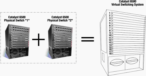
Het Virtual Switching System (VSS) is een nieuwe en innovatieve optie op Cisco Catalyst 6500 Series switches die effectief clustering van twee fysieke chassis in één logische eenheid toestaan. Een dergelijke technologie maakt nieuwe verbeteringen mogelijk op alle terreinen van de bedrijfscampagne en de invoering van datacenters, waaronder hoge beschikbaarheid, schaalbaarheid/prestaties, beheer en onderhoud.
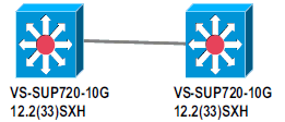
Huidige implementatie van VSS staat u toe om twee fysieke Cisco Catalyst 6500 Series switches samen te voegen in één logisch beheerde entiteit. Dit getal geeft een grafische weergave van dit concept waarbij twee 6509 chassis kunnen worden beheerd als één chassis met 18 sleuven zodra VSS is ingeschakeld:
Migratieproces
Ondersteuning van hardware en software
VSS is een software optie die alleen beschikbaar is voor Cisco Catalyst 6500 Series switches. Dit is nodig om deze functie in te schakelen en te configureren:
| Hardware | VS-S720-10G-3C/XL switch |
| in Cisco IOS®-software | Cisco IOS-softwarerelease 12.2(33)SXH1 of hoger |
| Modelnummer | Beschrijving |
| WS-C6503-E switch | E-Series chassis met 3 sleuven |
| WS-C6504-E switch | E-Series chassis met 4 sleuven |
| WS-C6506 | Chassis met 6 sleuven |
| WS-C6506-E switch | E-Series chassis met 6 sleuven |
| WS-C6509 | Chassis met 9 sleuven |
| WS-C6509-E switch | E-Series chassis met 9 sleuven |
| WS-C6509-NEB-A | Chassis met 9 sleuven verticaal Network Equipment Building Standards (NEBS) |
| WS-C6509-V-E switch | E-Series verticaal chassis met 9 sleuven |
| WS-C6513 | Chassis met 13 sleuven |
Deze tabel bevat een volledige lijst van het chassis dat wordt ondersteund met de eerste release van Cisco Virtual Switching System. Raadpleeg voor meer informatie Cisco Catalyst 6500 Series Virtual Switching System (VSS) 1440.
Migratiepaden
De tabel bevat een aantal mogelijke migratiepaden naar de VSS. Deze lijst is alleen suggestief en niet uitgebreid.
| Eerste instelling | upgrade vereist | Laatste instelling |
|---|---|---|
| Twee Cisco Catalyst 6500 Series switches met WS-SUP720-3B supervisors. |
hardware-upgrade - supervisor VS-S720-10G-3C/XL-software-upgrade - Cisco IOS 12.2(33)SXH1 of hoger | VSS |
| Twee Cisco Catalyst 6500 Series switches met VS-S720-10G-3C/XL toezichthouders. |
Software-upgrade - Cisco IOS 12.2(33)SXH1 of hoger | VSS |
Overzicht van migratie
Gemeenschappelijke configuratie in standalone omgeving
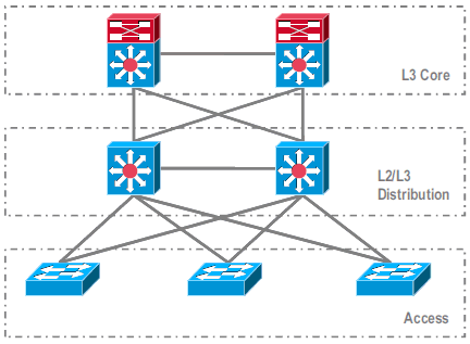
Functies of protocollen die werken tussen Layer 3 (L3) Core en L2/L3 Distributie:
-
IP-routingprotocollen
-
L3 poortkanalen of GelijkKost MultiPath-functie van IP-routing
Functies of protocollen die tussen L2/L3-distributie en toegangslaag lopen:
-
Spanning Tree Protocol
-
Eerste hop-routingprotocollen (FHRP)
-
Beleid: QoS, ACL
-
L2-trunks, VLAN’s, poortkanalen
Migratie naar VSS
Dit is een proces dat meerdere stappen omvat en elke stap wordt in dit gedeelte uitgelegd.
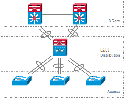
Migratiestappen tussen Core- en distributielaag:
-
MultiChassis EtherChannel (MEC) configureren
-
IP-routingconfiguratie wijzigen en opdrachten verwijderen, die niet meer nodig zijn
Migratiestappen tussen distributie en toegangslaag:
-
MEC configureren
-
Spanning Spanning Tree Protocol ingeschakeld
-
FHRP-opdrachten wijzigen
-
QoS- en ACL-beleid verplaatsen naar MEC (indien nodig)
-
De configuratie van L2-trunks verplaatsen naar MEC
stap voor stap
Voer de volgende stappen uit:
-
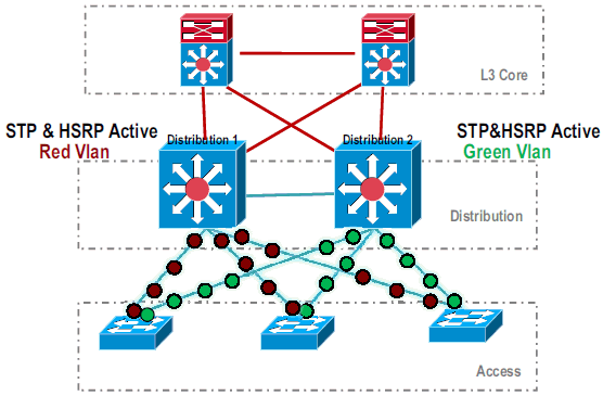
In de eerste standalone instelling is het verkeer vaak belastingsgebalanceerd onder Distributie-switches die gebruik maken van het delen van VLAN-lading en de HSRP-configuratie.
-
Wijzig de HSRP- en STP-configuratie zodat Distribution-1 actief is voor alle stromen, en aangrenzende apparaten deze verandering detecteren en al het verkeer naar Distribution-1 verzenden.
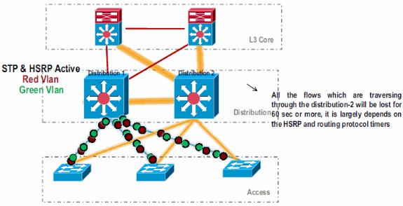
-
Sluit de fysieke interfaces van Distributie-2 af, zodat deze van het netwerk worden geïsoleerd.
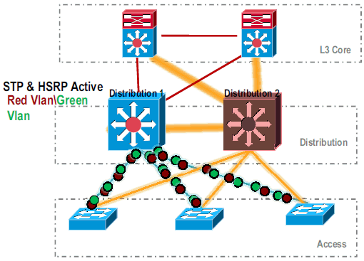
.
Zodra de Distribution-2 volledig uit het netwerk is verwijderd, kan deze worden geconverteerd naar VSS-modus zonder het productieverkeer te verstoren.
-
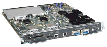
Indien niet eerder geïnstalleerd, installeer de nieuwe supervisor (VS-SUP720-10G) en controleer de status.
Distribution-2#show module
Mod Ports Card Type                              Model              Serial No.
--- ----- -------------------------------------- ------------------ -----------
  5    5  Supervisor Engine 720 10GE (Active)    VS-S720-10G        SAD104707BB
  9   48  CEF 720 48 port 10/100/1000mb Ethernet WS-X6748-GE-TX     SAL1020NGY3
-
Kopieer VSS compatibele Cisco IOS-software naar de sup-bootdisk:
Distribution-2#copy ftp: sup-bootdisk:
Address or name of remote host []? 172.16.85.150
Source filename []? s72033-ipservices_wan_vz.122-33.SXH1.bin
Destination filename [s72033-ipservices_wan_vz.122-33.SXH1.bin]?
Accessing ftp://172.16.85.150/s72033-ipservices_wan_vz.122-33.SXH1.bin...
-
Update de trap om Cisco IOS software te laden die naar de sup-bootdisk is gekopieerd:
Distribution-2(config)#boot system flash sup-bootdisk:s72033-ipservices_wan_vz.122-33.SXH1.bin -
Om de switch Distribution-2 in VSS-modus te kunnen gebruiken, is een Virtual Switch Link (VSL) vereist. De huidige link van het poortkanaal tussen Distribution-1 en Distribution-2 kan worden gebruikt voor de VSL-indeling.
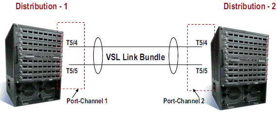
-
Configuratie van de eigenschappen van de Virtuele Switch:
-
Virtual Switch Domain Number (uniek binnen het netwerk)
-
Virtual Switch Number (uniek binnen het domein)
-
Virtual Switch Link (VSL)
Distribution-2(config)#hostname VSS

VSS(config)#switch virtual domain 100

VSS(config-vs-domain)#switch 1


!--- After conversion Distribution-2 will be noted !--- as Switch 1 in VSS mode.

VSS(config-vs-domain)# exit
VSS(config)#interface port-channel 1
VSS(config-if)#switch virtual link 1

VSS(config-if)#interface TenG 5/4
VSS(config-if)#channel-group 1 mode on
VSS(config-if)#interface TenG 5/5
VSS(config-if)#channel-group 1 mode on
VSS(config-if)# ^Z
VSS#
-
-
Converteer de Distribution-2 switch naar VSS-modus.
Opmerking: Geef deze opdracht uit via de console van de switch:
VSS#switch convert mode virtual

This command will convert all interface
names to naming convention "interface-type
switch-number/slot/port",
save the running config to startup-config and
reload the switch.
Do you want to proceed? [yes/no]: yes
Converting interface names
Building configuration...


!--- At this point the switch will reboot


!--- snippet of the console output

System detected Virtual Switch configuration...
 Interface TenGigabitEthernet 1/5/4 is member of
PortChannel 1
 Interface TenGigabitEthernet 1/5/5 is member of
PortChannel 1

!--- snippet of the console output

00:00:23: %PFREDUN-6-ACTIVE: Initializing as ACTIVE
processor for this switch

!--- snippet of the console output

00:00:28: %VSL_BRINGUP-6-MODULE_UP: VSL module in slot 5
switch 1 brought up
Initializing as Virtual Switch Active
-
Controleer de conversie van de Distribution-2 switch naar VSS-modus.
VSS#show switch virtual role

Switch  Switch Status  Preempt    Priority   Role     Session ID
        Number         Oper(Conf) Oper(Conf)          Local  Remote
-------------------------------------------------------------------
LOCAL    1     UP      FALSE(N)    110(110)  ACTIVE    0      0

In dual-active recovery mode: No
De switch Distribution-2 wordt met succes geconverteerd en werkt in VSS-modus. Er kunnen ook pre-configuratiestappen worden uitgevoerd na het converteren van de Distribution-1 switch. Echter, pre-configuratie helpt de hoeveelheid pakketverlies tijdens migratie te verminderen.
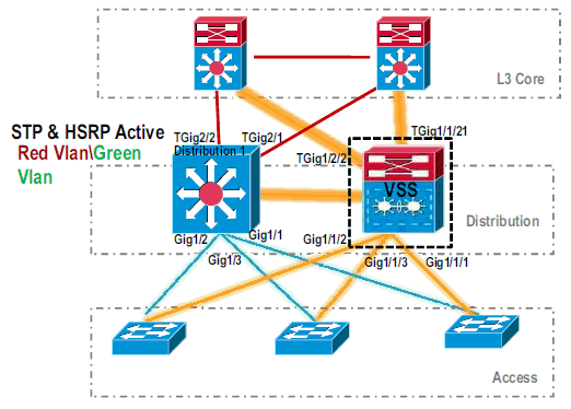
-
Volg deze stappen om VSS-Switch 1 vooraf te configureren:
-
Configureer MEC met de lokale interfaces van Switch-1. Interfaces van Switch-2 (momenteel distributie-1) kunnen aan MEC worden toegevoegd na conversie naar VSS-modus.
-
MEC configureren
-
Verplaats de interfaceconfiguratie naar MEC.
-
Verplaats het QoS- en ACL-beleid naar MEC.
Wijzigingen in configuratieinterface TenGigabitEthernet1/2/1 ip address 192.168.4.2 255.255.255.0 interface GigabitEthernet1/1/2 switchport switchport trunk encapsulation dot1q switchport trunk allowed vlan 10,20
Configuratie van aangrenzende apparaten om poortkanaal aan te passen!--- MEC to Core layer VSS(config)# int ten 1/2/1 VSS(config-if)# no ip address VSS(config-if)# interface po20 VSS(config-if)# ip address 192.168.4.2 255.255.255.0 VSS(config-if)# no shut VSS(config-if)# interface ten1/2/1 VSS(config-if)# channel-group 20 mode desirable !--- MEC to Access layer VSS(config-if)# interface po10 VSS(config-if)# switchport VSS(config-if)# switchport trunk encapsulation dot1q VSS(config-if)# switchport trunk allowed vlan 10,20 VSS(config-if)# no shut VSS(config-if)# interface gig1/1/2 VSS(config-if)# switchport VSS(config-if)# channel-group 10 mode desirable
De verbinding tussen VSS Switch-1 en de omringende apparaten is op dit moment stilgelegd. Daarom wordt een poortkanaal geconfigureerd zonder dat het doorstroming van het verkeer door Distribution-1 belemmert.
!--- In Core layer devices

Core(config)# int gig 1/1
Core(config-if)# no ip address
Core(config-if)# int po20
Core(config-if)# ip address 192.168.4.1 255.255.255.0
Core(config-if)# no shut
Core(config-if)# int gig 1/1
Core(config-if)# channel-group 20 mode desirable
!--- In Access layer devices

Access(config)# int po10
Access(config-if)# switchport
Access(config-if)# switchport trunk encapsulation dot1q
Access(config-if)# switchport trunk
Access(config-if)# no shut
Access(config-if)# int gig 1/1
Access(config-if)# channel-group 10 mode desirable
-
-
In VSS, zowel actieve als standby chassis gebruikt actieve chassis gebrand in MAC adres en VLAN IP adres. HSRP is niet langer vereist.
-
Verplaats de virtuele IP-adressen van HSRP naar de VLAN-interfaces.
-
Verwijder de HSRP-configuratie van de VLAN-interfaces.
Wijzigingen in configuratieinterface Vlan10 ip address 10.1.1.2 255.255.255.0 standby 10 ip 10.1.1.1 standby 10 priority 110 ! interface Vlan20 ip address 20.1.1.2 255.255.255.0 standby 20 ip 20.1.1.1 standby 20 priority 110 !
VSS(config)# interface Vlan10
VSS(config-if)# no standby 10 ip 10.1.1.1
VSS(config-if)# no standby 10 priority 110
VSS(config-if)# ip address 10.1.1.1 255.255.255.0
VSS(config-if)# interface Vlan20
VSS(config-if)# no standby 20 ip 20.1.1.1
VSS(config-if)# no standby 20 priority 110
VSS(config-if)# ip address 20.1.1.1 255.255.255.0
Opmerking: Eindapparaten zouden nog steeds hun ARP-items richten op het oorspronkelijke HSRP MAC-adres. Totdat deze inzendingen tijd uit of een ander ARP wordt verzonden om hun cache bij te werken, is er enig aansluitingsverlies.
-
-
Schakel de NSF-SSO-functie in voor de IP routingprotocollen die worden gebruikt. VSS vereenvoudigt de routingconfiguratie, zodat sommige netwerkverklaringen niet meer nodig zijn. Daarom kunnen zij worden geschrapt.
VSS Switch-1
kernVSS#show running-config | begin ospf router ospf 1 log-adjacency-changes network 10.1.1.0 0.0.0.255 area 0 network 20.1.1.0 0.0.0.255 area 0 network 192.168.4.0 0.0.0.255 area 0 network 192.168.5.0 0.0.0.255 area 0 !--- rest of output elided !--- Previous L3 interfaces are merged as MEC, hence some routing statements are no longer required. VSS(config)# router ospf 1 VSS(config-router)# nsf VSS(config-router)# no network 192.168.5.0 0.0.0.255 area 0
Core#show running-config | begin ospf
router ospf 1
 log-adjacency-changes
 network 192.168.4.0 0.0.0.255 area 0
 network 192.168.5.0 0.0.0.255 area 0

!--- rest of output elided


!--- Previous L3 interfaces are merged as MEC, hence some routing statements are no longer required.


Core(config)# router ospf 1
Core(config-router)# nsf
Core(config-router)# no network 192.168.5.0 0.0.0.255 area 0
-
Wijzig de STP-configuratie zodat VSS Switch-1 de basis voor alle VLAN’s wordt.
-
-
Controleer de configuratie en connectiviteit van VSS Switch-1.
-
Schakel VSS Switch-1 interfaces in.
-
Controleer L2 connectiviteit aan de apparaten van de toegangslaag.
-
Controleer L3 connectiviteit op de apparaten van de Kernlaag.
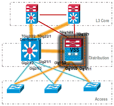
-
-
Nadat de connectiviteit van VSS Switch-1 wordt geverifieerd, sluit de interfaces van Distributie-1 om het verkeer aan VSS te switches.
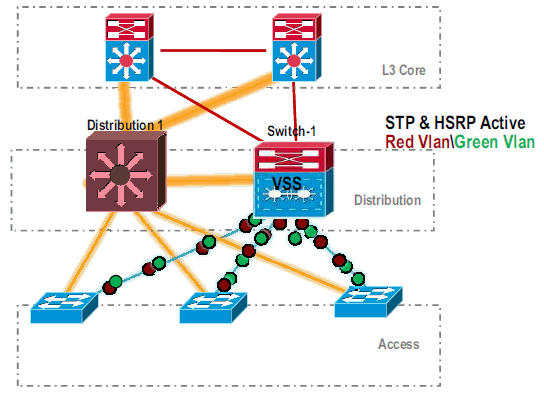
-
Herhaal de conversiestappen op de Distribution-1 switch om dit in de voorkeursmodus VSS-stand te brengen.
Distribution-1(config)#hostname VSS

VSS(config)#switch virtual domain 100

VSS(config-vs-domain)#switch 2


!--- After conversion Distribution-1 will be noted !--- as Switch 2 in VSS mode.

VSS(config-vs-domain)# exit
VSS(config)#interface port-channel 2
VSS(config-if)#switch virtual link 2

VSS(config-if)#interface TenG 5/4
VSS(config-if)#channel-group 2 mode on
VSS(config-if)#interface TenG 5/5
VSS(config-if)#channel-group 2 mode on
VSS(config-if)# ^Z
VSS#

VSS#switch convert mode virtual

This command will convert all interface
names to naming convention "interface-type
switch-number/slot/port",
save the running config to startup-config and
reload the switch.
Do you want to proceed? [yes/no]: yes
Converting interface names
Building configuration...


!--- At this point the switch will reboot


!--- snippet of the console output

System detected Virtual Switch configuration...
 Interface TenGigabitEthernet 2/5/4 is member of
PortChannel 2
 Interface TenGigabitEthernet 2/5/5 is member of
PortChannel 2

!--- snippet of the console output

00:00:23: %PFREDUN-6-ACTIVE: Initializing as ACTIVE
processor for this switch

!--- snippet of the console output

00:00:28: %VSL_BRINGUP-6-MODULE_UP: VSL module in slot 5
switch 2 brought up
Initializing as Virtual Switch Standby
-
Nadat de VSS standby switch is opgestart, wordt de actieve configuratie van VSS automatisch gesynchroniseerd in VSS standby. Na het opstarten zijn de interfaces van VSS standby (Switch-2) in shutdown toestand.
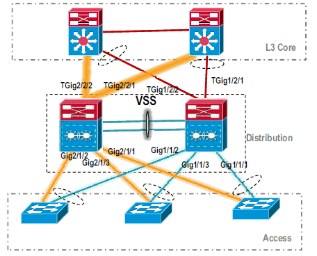
-
De configuratie van de virtuele switch voltooien.
Opmerking: deze laatste, kritieke stap is alleen van toepassing voor een eerste conversie. Als de switch al geconverteerd of gedeeltelijk geconverteerd is, kunt u deze opdracht niet gebruiken. Er wordt een foutbericht gegenereerd als de switch is geconverteerd of gedeeltelijk geconverteerd:
11:27:30: %PM-SP-4-ERR_DISABLE: channel-misconfig error detected
on Po110, putting Gi9/2 in err-disable state
U kunt deze opdracht uitgeven om automatisch de stand-by configuratie van de virtuele switch op de actieve virtuele switch te configureren:
VSS#switch accept mode virtual

This command will bring in all VSL configurations from the standby
switch and populate it into the running configuration.
In addition the startup configurations will be updated with the
new merged configurations.
Do you want proceed? [yes/no]: yes
Merging the standby VSL configuration. . .
Building configuration...
N.B.: Let erop dat de switch modus accepteert virtuele opdracht niet langer nodig is in Cisco IOS-softwarerelease 12.2 SXI omdat de configuraties automatisch worden samengevoegd.
-
Voeg de Switch-2 interfaces toe aan MEC.
- VSS
!--- To Core layer

VSS(config)# interface range tengig 1/2/1, tengig2/2/1
VSS(config-if-range)# channel-group 20 mode desirable
VSS(config-if-range)# no shut


!--- To Access layer

VSS(config)# interface range gig 1/1/2, gig 2/1/2
VSS(config-if-range)# switchport
VSS(config-if-range)# channel-group 10 mode desirable
VSS(config-if-range)# no shut
- VSS buurman - Core
Core(config)# interface range gig 1/1, gig 1/2
Core(config-if-range)# channel-group 20 mode desirable
Core(config-if-range)# no shut
- VSS buurman - toegang
Access(config)# interface range gig 1/1, gig 1/2
Access(config-if-range)# channel-group 10 mode desirable
Access(config-if-range)# no shut
Migratie naar VSS is voltooid. Op dit punt, lopen beide switches van VSS en het verkeer is lading-gebalanceerd op alle uplink interfaces.
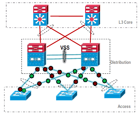
- VSS
Gerelateerde informatie
- Virtuele switchingsystemen configureren
- Cisco IOS virtuele Switch-opdracht - handleiding
- Productondersteuning voor Cisco Catalyst 6500 Virtual Switching System 1440
- Productondersteuning voor switches
- Ondersteuning voor LAN-switching technologie
- Technische ondersteuning en documentatie – Cisco Systems
Revisiegeschiedenis
| Revisie | Publicatiedatum | Opmerkingen |
|---|---|---|
1.0 |
01-Dec-2013 |
Eerste vrijgave |
Contact Cisco
- Een ondersteuningscase openen

- (Vereist een Cisco-servicecontract)

 Feedback