FlexVPN HA 듀얼 허브 컨피그레이션 예
다운로드 옵션
편견 없는 언어
본 제품에 대한 문서 세트는 편견 없는 언어를 사용하기 위해 노력합니다. 본 설명서 세트의 목적상, 편견 없는 언어는 나이, 장애, 성별, 인종 정체성, 민족 정체성, 성적 지향성, 사회 경제적 지위 및 교차성에 기초한 차별을 의미하지 않는 언어로 정의됩니다. 제품 소프트웨어의 사용자 인터페이스에서 하드코딩된 언어, RFP 설명서에 기초한 언어 또는 참조된 서드파티 제품에서 사용하는 언어로 인해 설명서에 예외가 있을 수 있습니다. 시스코에서 어떤 방식으로 포용적인 언어를 사용하고 있는지 자세히 알아보세요.
이 번역에 관하여
Cisco는 전 세계 사용자에게 다양한 언어로 지원 콘텐츠를 제공하기 위해 기계 번역 기술과 수작업 번역을 병행하여 이 문서를 번역했습니다. 아무리 품질이 높은 기계 번역이라도 전문 번역가의 번역 결과물만큼 정확하지는 않습니다. Cisco Systems, Inc.는 이 같은 번역에 대해 어떠한 책임도 지지 않으며 항상 원본 영문 문서(링크 제공됨)를 참조할 것을 권장합니다.
목차
소개
이 문서에서는 인터넷과 같은 보안되지 않은 네트워크 매체를 통해 IPSec 기반 VPN을 통해 데이터 센터에 연결하는 원격 사무실에 대한 전체 이중화 설계를 구성하는 방법에 대해 설명합니다.
사전 요구 사항
요구 사항
이 문서에 대한 특정 요건이 없습니다.
사용된 구성 요소
이 문서의 정보는 다음 기술 구성 요소를 기반으로 합니다.
- BGP(Border Gateway Protocol)는 데이터 센터 내, VPN 오버레이의 스포크와 허브 간 라우팅 프로토콜입니다.
- BFD(Bidirectional Forwarding Detection)는 오버레이 터널이 아닌 데이터 센터 내에서만 실행되는 다운 링크(라우터 다운)를 탐지하는 메커니즘입니다.
- Cisco IOS® FlexVPN은 허브와 스포크 간, 짧은 컷 스위칭을 통해 스포크 투 스포크 기능을 지원합니다.
- 스포크가 다른 허브에 연결된 경우에도 스포크 투 스포크 통신을 활성화하기 위해 두 허브 간에 GRE(Generic Routing Encapsulation) 터널링이 터널링됩니다.
- 향상된 객체 추적 및 추적된 객체에 연결된 고정 경로
이 문서의 정보는 특정 랩 환경의 디바이스를 토대로 작성되었습니다.이 문서에 사용된 모든 디바이스는 초기화된(기본) 컨피그레이션으로 시작되었습니다.현재 네트워크가 작동 중인 경우, 모든 명령어의 잠재적인 영향을 미리 숙지하시기 바랍니다.
배경 정보
데이터 센터용 원격 액세스 솔루션을 설계할 때 미션 크리티컬 사용자 애플리케이션의 핵심 요구 사항은 HA(고가용성)입니다.
이 문서에 제시된 솔루션을 사용하면 다시 로드, 업그레이드 또는 전원 문제로 인해 VPN 종료 허브 중 하나가 중단되는 오류 시나리오를 신속하게 탐지하고 복구할 수 있습니다.그런 다음 모든 Remote Office 라우터(스포크)는 장애가 감지되면 즉시 다른 운영 허브를 사용합니다.
이 설계의 장점은 다음과 같습니다.
- VPN 허브 다운 시나리오에서 신속한 네트워크 복구
- VPN 허브 간에 복잡한 스테이트풀 동기화(예: IPSec SA(Security Associations), ISAKMP(Internet Security Association and Key Management Protocol) SA, Crypto-routing) 없음
- IPSec 스테이트풀 HA와의 ESP(Encapsulating Security Payload) 시퀀스 번호 동기화 지연으로 인한 재전송 방지 문제 없음
- VPN 허브는 서로 다른 Cisco IOS/IOS-XE 기반 하드웨어 또는 소프트웨어를 사용할 수 있습니다.
- VPN 오버레이에서 실행되는 라우팅 프로토콜로서 BGP를 통한 유연한 로드 밸런싱 구현 선택
- 백그라운드에서 실행되는 숨겨진 메커니즘 없이 모든 디바이스에서 읽기 가능한 라우팅 지우기
- 직접 스포크 투 스포크 연결
- AAA(Authentication, Authorization, and Accounting) 통합 및 터널당 QoS(Quality of Service)를 포함하는 모든 FlexVPN 이점
구성
이 섹션에서는 예제 시나리오를 제공하고 보안되지 않은 네트워크 매체를 통해 IPSec 기반 VPN을 통해 데이터 센터에 연결하는 원격 사무실에 대해 완전한 이중화 설계를 구성하는 방법에 대해 설명합니다.
참고:이 섹션에 사용된 명령에 대한 자세한 내용을 보려면 Command Lookup Tool(등록된 고객만 해당)을 사용합니다.
네트워크 다이어그램
이 문서에서 사용되는 네트워크 토폴로지입니다.

참고:이 토폴로지에서 사용되는 모든 라우터는 Cisco IOS Version 15.2(4)M1을 실행하며, 인터넷 클라우드는 172.16.0.0/24의 주소 체계를 사용합니다.
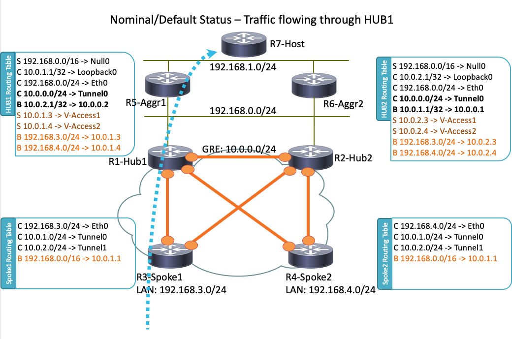
일반 운영 시나리오
정상적인 운영 시나리오에서 모든 라우터가 작동 및 작동하면 모든 스포크 라우터가 기본 허브(R1-HUB1)를 통해 모든 트래픽을 라우팅합니다. 이 라우팅 환경설정은 기본 BGP 로컬 환경설정이 200으로 설정된 경우(자세한 내용은 다음 섹션을 참조) 달성됩니다. 이 설정은 트래픽 로드 밸런싱과 같은 배치 요구 사항을 기반으로 조정할 수 있습니다.
스포크 투 스포크(바로 가기)
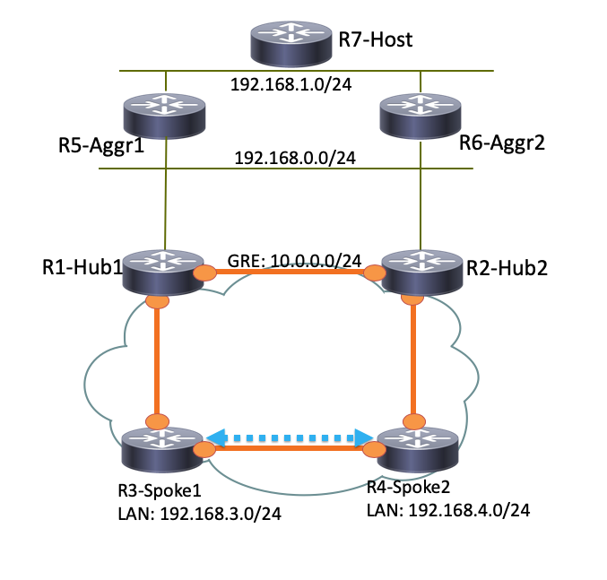
R3-Spoke1이 R4-Spoke2에 대한 연결을 시작하면 단축 스위칭 컨피그레이션으로 동적 스포크 투 스포크 터널이 생성됩니다.
팁:자세한 내용은 FlexVPN Spoke to Spoke 구성 설명서를 참조하십시오.
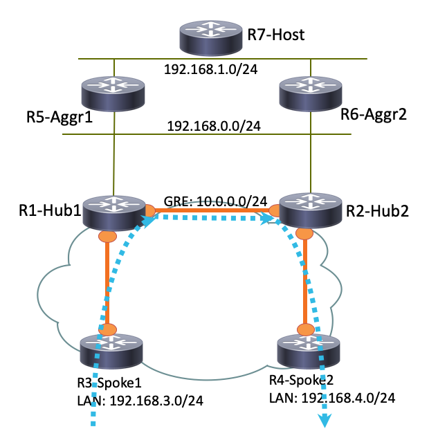
R3-Spoke1이 R1-HUB1에만 연결되어 있고 R4-Spoke2가 R2-HUB2에만 연결되어 있는 경우 허브 간에 실행되는 포인트-투-포인트 GRE 터널을 사용하여 직접 스포크-스포크 연결을 계속 수행할 수 있습니다.이 경우 R3-Spoke1과 R4-Spoke2 사이의 초기 트래픽 경로는 다음과 같이 나타납니다.

R1-Hub1은 GRE 터널과 동일한 NHRP(Next Hop Resolution Protocol) 네트워크 ID를 가진 가상 액세스 인터페이스에서 패킷을 수신하므로 트래픽 표시는 R3-Spoke1로 전송됩니다. 이렇게 하면 스포크-스포크 동적 터널 생성이 트리거됩니다.

정규 운영 시나리오에 대한 라우팅 테이블 및 출력
다음은 일반적인 운영 시나리오의 R1-HUB1 라우팅 테이블입니다.
R1-HUB1# show ip route
Codes: L - local, C - connected, S - static, R - RIP, M - mobile, B - BGP
       D - EIGRP, EX - EIGRP external, O - OSPF, IA - OSPF inter area
       N1 - OSPF NSSA external type 1, N2 - OSPF NSSA external type 2
       E1 - OSPF external type 1, E2 - OSPF external type 2
       i - IS-IS, su - IS-IS summary, L1 - IS-IS level-1, L2 - IS-IS level-2
       ia - IS-IS inter area, * - candidate default, U - per-user static route
       o - ODR, P - periodic downloaded static route, H - NHRP, l - LISP
       a - application route
       + - replicated route, % - next hop override

Gateway of last resort is not set

      10.0.0.0/8 is variably subnetted, 11 subnets, 3 masks
S        10.0.0.0/8 is directly connected, Null0
C        10.0.0.0/24 is directly connected, Tunnel0
L        10.0.0.1/32 is directly connected, Tunnel0
C        10.0.1.1/32 is directly connected, Loopback0
S        10.0.1.2/32 is directly connected, Virtual-Access1
S        10.0.1.3/32 is directly connected, Virtual-Access2
B        10.0.2.1/32 [200/0] via 10.0.0.2, 00:05:40
B        10.0.2.3/32 [200/0] via 10.0.0.2, 00:05:40
B        10.0.2.4/32 [200/0] via 10.0.0.2, 00:05:40
B        10.0.5.1/32 [200/0] via 192.168.0.5, 00:05:40
B        10.0.6.1/32 [200/0] via 192.168.0.6, 00:05:40
      172.16.0.0/16 is variably subnetted, 2 subnets, 2 masks
C        172.16.0.0/24 is directly connected, Ethernet0/0
L        172.16.0.1/32 is directly connected, Ethernet0/0
S     192.168.0.0/16 is directly connected, Null0
      192.168.0.0/24 is variably subnetted, 2 subnets, 2 masks
C        192.168.0.0/24 is directly connected, Ethernet0/2
L        192.168.0.1/32 is directly connected, Ethernet0/2
B     192.168.1.0/24 [200/0] via 192.168.0.5, 00:05:40
B     192.168.3.0/24 [200/0] via 10.0.1.4, 00:05:24
B     192.168.4.0/24 [200/0] via 10.0.1.5, 00:05:33
다음은 R4-SPOKE2와 스포크 간 터널을 생성한 후 정기적으로 작동하는 시나리오의 R3-SPOKE1 라우팅 테이블입니다.
R3-SPOKE1#  show ip route
Codes: L - local, C - connected, S - static, R - RIP, M - mobile, B - BGP
       D - EIGRP, EX - EIGRP external, O - OSPF, IA - OSPF inter area
       N1 - OSPF NSSA external type 1, N2 - OSPF NSSA external type 2
       E1 - OSPF external type 1, E2 - OSPF external type 2
       i - IS-IS, su - IS-IS summary, L1 - IS-IS level-1, L2 - IS-IS level-2
       ia - IS-IS inter area, * - candidate default, U - per-user static route
       o - ODR, P - periodic downloaded static route, H - NHRP, l - LISP
       a - application route
       + - replicated route, % - next hop override

Gateway of last resort is not set

      10.0.0.0/8 is variably subnetted, 8 subnets, 2 masks
B        10.0.0.0/8 [200/0] via 10.0.1.1, 00:06:27
H        10.0.0.1/32 is directly connected, 00:06:38, Tunnel1
S   %    10.0.1.1/32 is directly connected, Tunnel0
C        10.0.1.3/32 is directly connected, Tunnel0
H        10.0.1.4/32 is directly connected, 00:01:30, Virtual-Access1
S        10.0.2.1/32 is directly connected, Tunnel1
C        10.0.2.3/32 is directly connected, Tunnel1
H        10.0.2.4/32 [250/1] via 10.0.2.3, 00:01:30, Virtual-Access1
      172.16.0.0/16 is variably subnetted, 2 subnets, 2 masks
C        172.16.0.0/24 is directly connected, Ethernet0/0
L        172.16.0.3/32 is directly connected, Ethernet0/0
B     192.168.0.0/16 [200/0] via 10.0.1.1, 00:06:27
      192.168.3.0/24 is variably subnetted, 2 subnets, 2 masks
C        192.168.3.0/24 is directly connected, Ethernet0/1
L        192.168.3.3/32 is directly connected, Ethernet0/1
      192.168.4.0/32 is subnetted, 1 subnets
H        192.168.4.4 [250/1] via 10.0.1.3, 00:01:30, Virtual-Access1
R3-Spoke1에서 BGP 테이블에는192.168.0.0/16 네트워크에 대해 다른 로컬 환경 설정(R1-Hub1이 기본 설정)이 있는 두 개의 항목이 있습니다.
R3-SPOKE1#show ip bgp 192.168.0.0/16
BGP routing table entry for 192.168.0.0/16, version 8
Paths: (2 available, best #2, table default)
  Not advertised to any peer
  Refresh Epoch 1
  Local
    10.0.2.1 from 10.0.2.1 (10.0.2.1)
      Origin incomplete, metric 0, localpref 100, valid, internal
      rx pathid: 0, tx pathid: 0
  Refresh Epoch 1
  Local
    10.0.1.1 from 10.0.1.1 (10.0.1.1)
      Origin incomplete, metric 0, localpref 200, valid, internal, best
      rx pathid: 0, tx pathid: 0x0
다음은 일반적인 운영 시나리오의 R5-AGGR1 라우팅 테이블입니다.
R5-LAN1#show ip route
      10.0.0.0/8 is variably subnetted, 10 subnets, 3 masks
B        10.0.0.0/8 [200/0] via 192.168.0.1, 00:07:22
B        10.0.0.0/24 [200/0] via 192.168.0.1, 00:07:22
B        10.0.1.1/32 [200/0] via 192.168.0.1, 00:07:22
B        10.0.1.3/32 [200/0] via 192.168.0.1, 00:07:17
B        10.0.1.4/32 [200/0] via 192.168.0.1, 00:07:16
B        10.0.2.1/32 [200/0] via 192.168.0.2, 15:44:13
B        10.0.2.3/32 [200/0] via 192.168.0.2, 15:44:13
B        10.0.2.4/32 [200/0] via 192.168.0.2, 15:44:13
C        10.0.5.1/32 is directly connected, Loopback0
B        10.0.6.1/32 [200/0] via 192.168.0.6, 00:07:22
      172.16.0.0/24 is subnetted, 1 subnets
B        172.16.0.0 [200/0] via 192.168.0.1, 00:07:22
B     192.168.0.0/16 [200/0] via 192.168.0.1, 00:07:22
      192.168.0.0/24 is variably subnetted, 2 subnets, 2 masks
C        192.168.0.0/24 is directly connected, Ethernet0/0
L        192.168.0.5/32 is directly connected, Ethernet0/0
      192.168.1.0/24 is variably subnetted, 2 subnets, 2 masks
C        192.168.1.0/24 is directly connected, Ethernet0/1
L        192.168.1.5/32 is directly connected, Ethernet0/1
B     192.168.3.0/24 [200/0] via 10.0.1.3, 00:07:06
B     192.168.4.0/24 [200/0] via 10.0.1.4, 00:07:15
다음은 일반적인 운영 시나리오의 R7-HOST 라우팅 테이블입니다.
R7-HOST#show ip route
S*    0.0.0.0/0 [1/0] via 192.168.1.254
      192.168.1.0/24 is variably subnetted, 2 subnets, 2 masks
C        192.168.1.0/24 is directly connected, Ethernet0/0
L        192.168.1.7/32 is directly connected, Ethernet0/0
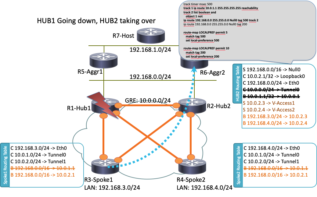
HUB1 실패 시나리오
다음은 R1-HUB1 다운 시나리오입니다(정전 또는 업그레이드와 같은 작업으로 인해).

이 시나리오에서는 다음과 같은 일련의 이벤트가 발생합니다.
- R2-HUB2 및 LAN 집계 라우터 R5-AGGR1 및 R6-AGGR2의 BFD는 R1-HUB1의 다운 상태를 감지합니다. 따라서 BGP 인접 디바이스가 즉시 다운됩니다.
- R1-HUB1 루프백 발생을 탐지하는 R2-HUB2에 대한 추적 객체 감지(예 컨피그레이션의 트랙 1)
- 이 다운된 추적 개체는 다른 트랙의 실행을 트리거합니다(논리적 NOT). 이 예에서는 트랙 1이 다운될 때마다 트랙 2가 올라갑니다.
- 이렇게 하면 기본 관리 거리보다 낮은 값으로 인해 라우팅 테이블에 정적 IP 라우팅 항목이 추가됩니다.관련 컨피그레이션은 다음과 같습니다.
! Routes added when second HUB is down
ip route 10.0.0.0 255.0.0.0 Null0 tag 500 track 2
ip route 192.168.0.0 255.255.0.0 Null0 tag 500 track 2

! Default static routes are with Tag 200 and admin distance of 150
ip route 10.0.0.0 255.0.0.0 Null0 150 tag 200
ip route 192.168.0.0 255.255.0.0 Null0 150 tag 200 - R2-HUB2는 R1-HUB1에 설정된 값보다 큰 BGP 로컬 환경 설정을 사용하여 이러한 고정 경로를 재배포합니다. 이 예에서는 R1-HUB1에 의해 설정된 200 대신 실패 시나리오에 500의 로컬 환경 설정이 사용됩니다.
route-map LOCALPREF permit 5
 match tag 500
 set local-preference 500
!
route-map LOCALPREF permit 10
 match tag 200
 set local-preference 200
!
R3-Spoke1에서는 BGP 출력에서 이를 확인할 수 있습니다.R1 항목은 여전히 존재하지만 사용되지 않습니다.
R3-SPOKE1#show ip bgp 192.168.0.0/16
BGP routing table entry for 192.168.0.0/16, version 10
Paths: (2 available, best #1, table default)
  Not advertised to any peer
  Refresh Epoch 1
  Local
    10.0.2.1 from 10.0.2.1 (10.0.2.1)
      Origin incomplete, metric 0, localpref 500, valid, internal, best
      rx pathid: 0, tx pathid: 0x0
  Refresh Epoch 1
  Local
    10.0.1.1 from 10.0.1.1 (10.0.1.1)
      Origin incomplete, metric 0, localpref 200, valid, internal
rx pathid: 0, tx pathid: 0 - 이 시점에서 두 스포크(R3-Spoke1 및 R4-Spoke2)가 모두 R2-HUB2로 트래픽을 보내기 시작합니다. 이러한 모든 단계는 1초 내에 이루어져야 합니다.다음은 Spoke 3의 라우팅 테이블입니다.
R3-SPOKE1#show ip route
      10.0.0.0/8 is variably subnetted, 5 subnets, 2 masks
B        10.0.0.0/8 [200/0] via 10.0.2.1, 00:00:01
S        10.0.1.1/32 is directly connected, Tunnel0
C        10.0.1.3/32 is directly connected, Tunnel0
S        10.0.2.1/32 is directly connected, Tunnel1
C        10.0.2.3/32 is directly connected, Tunnel1
      172.16.0.0/16 is variably subnetted, 2 subnets, 2 masks
C        172.16.0.0/24 is directly connected, Ethernet0/0
L        172.16.0.3/32 is directly connected, Ethernet0/0
B     192.168.0.0/16 [200/0] via 10.0.2.1, 00:00:01
      192.168.3.0/24 is variably subnetted, 2 subnets, 2 masks
C        192.168.3.0/24 is directly connected, Ethernet0/1
L 192.168.3.3/32 is directly connected, Ethernet0/1 - 스포크와 R1-HUB1 간의 이후 BGP 세션이 중단되고 DPD(Dead Peer Detection)는 R1-HUB1에서 종료되는 IPSec 터널을 제거합니다. 그러나 R2-HUB2가 이미 기본 터널 종료 게이트웨이로 사용되므로 트래픽 전달에 영향을 주지 않습니다.
R3-SPOKE1#show ip bgp 192.168.0.0/16
BGP routing table entry for 192.168.0.0/16, version 10
Paths: (1 available, best #1, table default)
  Not advertised to any peer
  Refresh Epoch 1
  Local
    10.0.2.1 from 10.0.2.1 (10.0.2.1)
      Origin incomplete, metric 0, localpref 500, valid, internal, best
      rx pathid: 0, tx pathid: 0x0
구성
이 섹션에서는 이 토폴로지에서 사용되는 허브 및 스포크의 샘플 컨피그레이션을 제공합니다.
R1-HUB 컨피그레이션
version 15.4
!
hostname R1-HUB1
!
aaa new-model
!
aaa authorization network default local
!
aaa session-id common
!
! setting track timers to the lowest possible (the lower this value is
! the faster router will react
track timer ip route msec 500
!
! Monitoring of HUB2's loopback present in routing table
! If it is present it will mean that HUB2 is alive
track 1 ip route 10.0.2.1 255.255.255.255 reachability
!
! Monitoring of loopback of R5-AGGR-1
track 3 ip route 10.0.5.1 255.255.255.255 reachability
!
! Monitoring of loopback of R6-AGGR-2
track 4 ip route 10.0.6.1 255.255.255.255 reachability
!
! Track 2 should be UP only when HUB2 is not available and both AGGRE routers are up
!
track 2 list boolean and
 object 1 not
 object 3
 object 4
!

! IKEv2 Config Exchange configuration (IP addresses for spokes are assigned from pool)
crypto ikev2 authorization policy default
 pool SPOKES
 route set interface
 route accept any tag 20
!
!
! IKEv2 profile for Spokes - Smart Defaults used
crypto ikev2 profile default
 match identity remote any
 authentication remote pre-share key cisco
 authentication local pre-share key cisco
 aaa authorization group psk list default default
 virtual-template 1
!
interface Loopback0
 ip address 10.0.1.1 255.255.255.255
!
! GRE Tunnel configured to second HUB. It is required for spoke-to-spoke connectivity
! to work in all possible circumstances
! no BFD echo configuration is required to avoid Traffic Indication sent by remote HUB
! (BFD echo is having the same source and destination IP address)
!
interface Tunnel0
 ip address 10.0.0.1 255.255.255.0
 ip nhrp network-id 1
 ip nhrp redirect
 bfd interval 50 min_rx 50 multiplier 3
 no bfd echo
 tunnel source Ethernet0/2
 tunnel destination 192.168.0.2
!
interface Ethernet0/0
 ip address 172.16.0.1 255.255.255.0
!
interface Ethernet0/2
 ip address 192.168.0.1 255.255.255.0
 bfd interval 50 min_rx 50 multiplier 5
!
interface Virtual-Template1 type tunnel
 ip unnumbered Loopback0
 ip nhrp network-id 1
 ip nhrp redirect
 tunnel protection ipsec profile default
!
! BGP Configuration
router bgp 1
 bgp log-neighbor-changes
! dynamic peer-groups are used for AGGR routers and SPOKES
 bgp listen range 192.168.0.0/24 peer-group DC
 bgp listen range 10.0.1.0/24 peer-group SPOKES
! BGP timers configured
 timers bgp 15 30
 neighbor SPOKES peer-group
 neighbor SPOKES remote-as 1
 neighbor DC peer-group
 neighbor DC remote-as 1
! Within DC BFD is used to determine neighbour status
 neighbor DC fall-over bfd
 neighbor 10.0.0.2 remote-as 1
! BFD is used to detect HUB2 status
 neighbor 10.0.0.2 fall-over bfd
 !
 address-family ipv4
  redistribute connected
! route-map which determines what should be the local-pref
  redistribute static route-map LOCALPREF
  neighbor SPOKES activate
! to spokes only Aggregate/Summary routes are sent
  neighbor SPOKES route-map AGGR out
  neighbor DC activate
  neighbor DC route-reflector-client
  neighbor 10.0.0.2 activate
  neighbor 10.0.0.2 route-reflector-client
 exit-address-family
!
ip local pool SPOKES 10.0.1.2 10.0.1.254
!
! When HUB2 goes down Static Routes with Tag 500 are added and admin distance of 1
ip route 10.0.0.0 255.0.0.0 Null0 tag 500 track 2
ip route 192.168.0.0 255.255.0.0 Null0 tag 500 track 2
! Default static routes are with Tag 200 and admin distance of 150
ip route 10.0.0.0 255.0.0.0 Null0 150 tag 200
ip route 192.168.0.0 255.255.0.0 Null0 150 tag 200
!
!
ip prefix-list AGGR seq 5 permit 192.168.0.0/16
ip prefix-list AGGR seq 10 permit 10.0.0.0/8
!
route-map AGGR permit 10
 match ip address prefix-list AGGR
!
route-map LOCALPREF permit 5
 match tag 500
 set local-preference 500
!
route-map LOCALPREF permit 10
 match tag 200
 set local-preference 200
!
route-map LOCALPREF permit 15
 match tag 20
R2-HUB2 컨피그레이션
hostname R2-HUB2
!
aaa new-model
!
aaa authorization network default local
!
track timer ip route msec 500
!
track 1 ip route 10.0.1.1 255.255.255.255 reachability
!
track 2 list boolean and
 object 1 not
 object 3
 object 4
!
track 3 ip route 10.0.5.1 255.255.255.255 reachability
!
track 4 ip route 10.0.6.1 255.255.255.255 reachability
!
!
crypto ikev2 authorization policy default
 pool SPOKES
 route set interface
 route accept any tag 20
!
!
crypto ikev2 profile default
 match identity remote any
 authentication remote pre-share key cisco
 authentication local pre-share key cisco
 aaa authorization group psk list default default
 virtual-template 1
!
!
interface Loopback0
 ip address 10.0.2.1 255.255.255.255
!
interface Tunnel0
 ip address 10.0.0.2 255.255.255.0
 ip nhrp network-id 1
 ip nhrp redirect
 bfd interval 50 min_rx 50 multiplier 3
 no bfd echo
 tunnel source Ethernet0/2
 tunnel destination 192.168.0.1
!
interface Ethernet0/0
 ip address 172.16.0.2 255.255.255.0
!
interface Ethernet0/2
 ip address 192.168.0.2 255.255.255.0
 bfd interval 50 min_rx 50 multiplier 5
!
interface Virtual-Template1 type tunnel
 ip unnumbered Loopback0
 ip nhrp network-id 1
 ip nhrp redirect
 tunnel protection ipsec profile default
!
router bgp 1
 bgp log-neighbor-changes
 bgp listen range 192.168.0.0/24 peer-group DC
 bgp listen range 10.0.2.0/24 peer-group SPOKES
 timers bgp 15 30
 neighbor SPOKES peer-group
 neighbor SPOKES remote-as 1
 neighbor DC peer-group
 neighbor DC remote-as 1
 neighbor DC fall-over bfd
 neighbor 10.0.0.1 remote-as 1
 neighbor 10.0.0.1 fall-over bfd
 !
 address-family ipv4
  redistribute connected
  redistribute static route-map LOCALPREF
  neighbor SPOKES activate
  neighbor SPOKES route-map AGGR out
  neighbor DC activate
  neighbor DC route-reflector-client
  neighbor 10.0.0.1 activate
  neighbor 10.0.0.1 route-reflector-client
 exit-address-family
!
ip local pool SPOKES 10.0.2.2 10.0.2.254
ip forward-protocol nd
!
!
ip route 192.168.0.0 255.255.0.0 Null0 tag 500 track 2
ip route 10.0.0.0 255.0.0.0 Null0 tag 500 track 2
ip route 10.0.0.0 255.0.0.0 Null0 150 tag 200
ip route 192.168.0.0 255.255.0.0 Null0 150 tag 200
!
!
ip prefix-list AGGR seq 5 permit 192.168.0.0/16
ip prefix-list AGGR seq 10 permit 10.0.0.0/8
!
route-map AGGR permit 10
 match ip address prefix-list AGGR
!
route-map LOCALPREF permit 5
 match tag 500
 set local-preference 500
!
route-map LOCALPREF permit 10
 match tag 200
 set local-preference 100
!
route-map LOCALPREF permit 15
 match tag 20
R3-SPOKE1 구성
hostname R3-SPOKE1
!
aaa new-model
!
aaa authorization network default local
!
!
crypto ikev2 authorization policy default
 route set interface
!
!
crypto ikev2 profile default
 match identity remote any
 authentication remote pre-share key cisco
 authentication local pre-share key cisco
 dpd 10 2 on-demand
 aaa authorization group psk list default default
!
! Tunnel to the HUB1
!
interface Tunnel0
 ip address negotiated
 ip nhrp network-id 1
 ip nhrp shortcut virtual-template 2
 tunnel source Ethernet0/0
 tunnel destination 172.16.0.1
 tunnel protection ipsec profile default
!
! Tunnel to the HUB2
!
interface Tunnel1
 ip address negotiated
 ip nhrp network-id 1
 ip nhrp shortcut virtual-template 2
 tunnel source Ethernet0/0
 tunnel destination 172.16.0.2
 tunnel protection ipsec profile default
!
interface Ethernet0/0
 description INTERNET-CLOUD
 ip address 172.16.0.3 255.255.255.0
!
interface Ethernet0/1
 description LAN
 ip address 192.168.3.3 255.255.255.0
!
interface Virtual-Template2 type tunnel
 ip unnumbered Ethernet0/1
 ip nhrp network-id 1
 ip nhrp shortcut virtual-template 2
 tunnel protection ipsec profile default
!
router bgp 1
 bgp log-neighbor-changes
 timers bgp 15 30
 neighbor 10.0.1.1 remote-as 1
 neighbor 10.0.2.1 remote-as 1
 !
 address-family ipv4
  network 192.168.3.0
  neighbor 10.0.1.1 activate
  neighbor 10.0.2.1 activate
 exit-address-family
R4-SPOKE2 구성
hostname R4-SPOKE2
!
aaa new-model
!
aaa authorization network default local
!
!
crypto ikev2 authorization policy default
 route set interface
!
crypto ikev2 profile default
 match identity remote any
 authentication remote pre-share key cisco
 authentication local pre-share key cisco
 dpd 10 2 on-demand
 aaa authorization group psk list default default
!
interface Tunnel0
 ip address negotiated
 ip nhrp network-id 1
 ip nhrp shortcut virtual-template 2
 tunnel source Ethernet0/0
 tunnel destination 172.16.0.1
 tunnel protection ipsec profile default
!
interface Tunnel1
 ip address negotiated
 ip nhrp network-id 1
 ip nhrp shortcut virtual-template 2
 tunnel source Ethernet0/0
 tunnel destination 172.16.0.2
 tunnel protection ipsec profile default
!
interface Ethernet0/0
 ip address 172.16.0.4 255.255.255.0
!
interface Ethernet0/1
 ip address 192.168.4.4 255.255.255.0
!
interface Virtual-Template2 type tunnel
 ip unnumbered Ethernet0/1
 ip nhrp network-id 1
 ip nhrp shortcut virtual-template 2
 tunnel protection ipsec profile default
!
router bgp 1
 bgp log-neighbor-changes
 timers bgp 15 30
 neighbor 10.0.1.1 remote-as 1
 neighbor 10.0.2.1 remote-as 1
 !
 address-family ipv4
  network 192.168.4.0
  neighbor 10.0.1.1 activate
  neighbor 10.0.2.1 activate
 exit-address-family
!
R5-AGGR1 컨피그레이션
hostname R5-LAN1
!
no aaa new-model
!
!
interface Loopback0
 ip address 10.0.5.1 255.255.255.255
!
interface Ethernet0/0
 ip address 192.168.0.5 255.255.255.0
 bfd interval 50 min_rx 50 multiplier 5
!
! HSRP configuration on the LAN side
!
interface Ethernet0/1
 ip address 192.168.1.5 255.255.255.0
 standby 1 ip 192.168.1.254
!
router bgp 1
 bgp log-neighbor-changes
 neighbor 192.168.0.1 remote-as 1
 neighbor 192.168.0.1 fall-over bfd
 neighbor 192.168.0.2 remote-as 1
 neighbor 192.168.0.2 fall-over bfd
 !
 address-family ipv4
  redistribute connected
  redistribute static
  neighbor 192.168.0.1 activate
  neighbor 192.168.0.2 activate
 exit-address-family
R6-AGGR2 컨피그레이션
hostname R6-LAN2
!
interface Loopback0
 ip address 10.0.6.1 255.255.255.255
!
interface Ethernet0/0
 ip address 192.168.0.6 255.255.255.0
 bfd interval 50 min_rx 50 multiplier 5
!
interface Ethernet0/1
 ip address 192.168.1.6 255.255.255.0
 standby 1 ip 192.168.1.254
 standby 1 priority 200
!
router bgp 1
 bgp log-neighbor-changes
 neighbor 192.168.0.1 remote-as 1
 neighbor 192.168.0.1 fall-over bfd
 neighbor 192.168.0.2 remote-as 1
 neighbor 192.168.0.2 fall-over bfd
 !
 address-family ipv4
  redistribute connected
  redistribute static
  neighbor 192.168.0.1 activate
  neighbor 192.168.0.2 activate
 exit-address-family
!
R7-HOST 컨피그레이션(해당 네트워크의 HOST 시뮬레이션)
hostname R7-HOST
!
no aaa new-model
!
interface Ethernet0/0
 ip address 192.168.1.7 255.255.255.0
!
ip route 0.0.0.0 0.0.0.0 192.168.1.254
중요 구성 참고 사항
이전 섹션에서 설명한 컨피그레이션에 대한 몇 가지 중요한 참고 사항은 다음과 같습니다.
- 모든 시나리오에서 스포크-스포크 연결이 작동하려면 두 허브 사이의 포인트-투-포인트 GRE 터널이 필요합니다. 특히 일부 스포크가 하나의 허브에 연결되고 다른 스포크만 다른 허브에 연결되는 시나리오를 포함하려면 이 터널이 필요합니다.
- 다른 허브에서 전송되는 트래픽 표시를 방지하기 위해 두 허브 간의 GRE 터널 인터페이스에서 bfd echo 컨피그레이션이 필요하지 않습니다.BFD Echo는 소스 및 대상 IP 주소가 동일하며, 이는 BFD Echo를 전송하는 라우터의 IP 주소와 동일합니다.이러한 패킷은 응답하는 라우터에 의해 다시 라우팅되므로 NHRP 트래픽 지표가 생성됩니다.
- BGP 컨피그레이션에서는 네트워크를 스포크로 광고하는 경로 맵 필터링이 필요하지 않지만, 집계/요약 경로만 알려지므로 컨피그레이션이 더 최적화됩니다.
neighbor SPOKES route-map AGGR out
- 허브에서 적절한 BGP 로컬 환경 설정을 설정하려면 route-map LOCALPREF 컨피그레이션이 필요하며, 재배포된 고정 경로를 요약 및 IKEv2 컨피그레이션 모드 경로로만 필터링합니다.
- 이 설계에서는 원격 사무실 위치(스포크)의 이중화를 다루지 않습니다. 스포크의 WAN 링크가 다운되면 VPN도 작동하지 않습니다.이 문제를 해결하려면 스포크 라우터에 두 번째 링크를 추가하거나 동일한 위치 내에 두 번째 스포크 라우터를 추가합니다.
요약하면, 이 문서에 제시된 이중화 설계는 SSO(Stateful Switchover)/상태 저장 기능의 현대적인 대안으로서 취급될 수 있습니다.유연성이 뛰어나며 특정 구축 요구 사항을 충족하기 위해 세부적으로 조정할 수 있습니다.
다음을 확인합니다.
현재 이 구성에 대해 사용 가능한 확인 절차가 없습니다.
문제 해결
현재 이 컨피그레이션에 사용할 수 있는 특정 문제 해결 정보가 없습니다.
관련 정보
Cisco 엔지니어가 작성
- Piotr KupisiewiczCisco TAC 엔지니어
- Wen ZhangCisco TAC 엔지니어
- Frederic DetienneCisco TAC 엔지니어
지원 문의
- 지원 케이스 접수

- (시스코 서비스 계약 필요)
 피드백
피드백