Aironet アクセス ポイントでの VLAN 設定例
内容
概要
このドキュメントでは、設定例を提供することにより、Command Line Interface(CLI; コマンドライン インターフェイス)を使用した Cisco Aironet Access Point(AP)での VLAN の設定方法を示しています。
前提条件
要件
この設定を行う前に、次の要件が満たされていることを確認します。
-
Aironet AP の基本的な設定に関する知識
-
Aironet Desktop Utility を使用した Aironet 802.11a/b/g クライアント アダプタの設定に関する知識
-
Cisco Catalyst スイッチと Cisco ルータの設定に関する基本的な知識
使用するコンポーネント
このドキュメントの情報は、次のソフトウェアとハードウェアのバージョンに基づいています。
-
Cisco IOS® ソフトウェア リリース 12.4(3g)JA1 が稼働する Aironet 1240AG シリーズ AP
-
Aironet 802.11a/b/g クライアント アダプタ
-
ファームウェア バージョン 2.5 が稼働する Aironet Desktop Utility
-
Cisco IOS ソフトウェア リリース 12.1(19)EA1 が稼働する Catalyst 2950 スイッチ
-
Cisco IOS ソフトウェア リリース 12.4(11)T が稼働する 2800 ISR ルータ
このドキュメントの情報は、特定のラボ環境にあるデバイスに基づいて作成されました。このドキュメントで使用するすべてのデバイスは、初期(デフォルト)設定の状態から起動しています。対象のネットワークが実稼働中である場合には、どのようなコマンドについても、その潜在的な影響について確実に理解しておく必要があります。
表記法
ドキュメント表記の詳細については、『シスコ テクニカル ティップスの表記法』を参照してください。
ネットワーク図
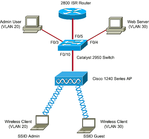
このドキュメントでは、次のネットワーク設定を使用します。
Aironet 1200 シリーズ AP に 3 つの VLAN(VLAN 2、VLAN 20、および VLAN 30)が設定されています。このドキュメントの設定では、VLAN 2 をネイティブ VLAN として使用し、VLAN 20 を管理部門(admin)の VLAN、VLAN 30 をゲスト ユーザとして使用します。管理部門に属する無線ユーザは AP に接続して、VLAN 20 の有線ネットワーク上の管理部門ユーザに接続できる必要があります。 無線ゲスト ユーザは、VLAN 30 の有線セグメント上にある Web サーバに接続できる必要があります。Catalyst 2950 スイッチは、AP を有線ネットワークに接続します。2800 ISRルータは同じスイッチに接続し、VLAN 20およびVLAN 30に属するワイヤレスクライアントのDHCPサーバとして機能します。ルータは、それぞれのサブネットからクライアントにIPアドレスを割り当てる必要があります。この設定を実装するには、AP、Catalyst スイッチ、ルータを設定する必要があります。

このドキュメントで使用されているデバイスは、次の IP アドレスのリストを使用しています。すべての IP アドレスは、/24 サブネット マスクを使用しています。
-
AP Bridge-Group Virtual Interface(BVI; ブリッジ グループ仮想インターフェイス)の IP アドレス(VLAN 2):172.16.1.20
-
VLAN 20 に接続する無線クライアント(SSID Admin)は、サブネット 172.16.2.0 からのルータの DHCP サーバから、IP アドレスを取得します。
-
VLAN 30 に接続する無線クライアント(SSID ゲスト)は、サブネット 172.16.3.0 からのルータの DHCP サーバから、IP アドレスを取得します。
-
VLAN 20 の有線ネットワークの上の管理ユーザ:172.16.2.60(スタティック IP)
-
VLAN 30 の Web サーバ:172.16.3.60(スタティック IP)
-
VLAN 2 のルータのサブインターフェイス:172.16.1.1
-
VLAN 20 のルータのサブインターフェイス:172.16.2.1
-
VLAN 30 のルータのサブインターフェイス:172.16.3.1
設定
このセクションでは、このドキュメントで説明する機能を設定するために必要な情報を提供しています。
注: このドキュメントで使用されているコマンドの詳細を調べるには、Command Lookup Tool(登録ユーザ専用)を使用してください。
AP を特定の VLAN に接続させるため、VLAN を認識する Service Set Identifier(SSID)を設定する必要があります。VLAN は VLAN ID または VLAN 名で識別されます。そのため、特定の VLAN ID または VLAN 名を認識する SSID を AP に設定すると、その VLAN への接続を確立できます。接続が確立されると、特定の SSID を使用して AP に接続した無線クライアントは、その SSID の VLAN に割り当てられます。AP には最大 16 の SSID を設定できるので、1 つの AP に 16 の VLAN を設定できます。AP に VLAN を設定し、接続を確立するためには、次の手順を実行します。
AP でのネイティブ VLAN の設定
アクセス ポイント自体と、アクセス ポイント接続先のスイッチなど、他のインフラストラクチャ デバイス間の VLAN は、ネイティブ VLAN と呼ばれています。アクセス ポイントのネイティブ VLAN は、通常、アクセス ポイントの上で設定された他の VLAN とは異なります。ネイティブ VLAN のサブネットで IP アドレスを割り当てられるアクセス ポイントの管理に使用されるのは、BVI インターフェイスです。たとえば、アクセス ポイント自身により送信されるか、アクセス ポイントに送信される管理トラフィックなどは、ネイティブ VLAN を想定しており、タグ付けされません。IEEE 802.1Q(dot1q)トランク ポートで受信されたタグなしのトラフィックはすべて、そのポートに設定されたネイティブ VLAN で転送されます。パケットが送信ポートのネイティブ VLAN ID と同じ VLAN ID を持つ場合、スイッチはタグなしでパケットを送信します。それ以外の場合は、スイッチはタグ付きでパケットを送信します。
AP にネイティブ VLAN を設定するには、AP のグローバル設定モードで次のコマンドを発行します。
AccessPoint<config>#interface fastethernet 0.2
AccessPoint<config-subif>#encapsulation dot1q 2 native

!--- Configure the encapsulation as dot1q and assign VLAN 2 as the native VLAN !--- on the Fast Ethernet interface.

AccessPoint<config-subif>#exit
AccessPoint<config>#interface dot11radio 0.2
AccessPoint<config-subif>#encapsulation dot1q 2 native

!--- Configure the encapsulation as dot1q and assign VLAN 2 as the native VLAN !--- on the radio interface.

AccessPoint<config-subif>#end
AP でのゲスト ユーザおよび管理者ユーザ用の VLAN の設定
次に、VLAN を 2 つ設定します。1 つはゲスト ユーザ用で、もう 1 つは管理部門ユーザ用です。SSID を特定の VLAN に関連付ける作業も必要です。この例では、次のように設定します。
-
管理部門ユーザ用に VLAN 20 を設定し、SSID は Admin を使用します。
-
ゲスト ユーザ用に VLAN 30 を設定し、SSID は Guest を使用します。
これらの VLAN を設定するには、グローバル設定モードに入り、次のコマンドを発行します。
AccessPoint#configure terminal

!--- Enter global configuration mode.

AccessPoint(config)#interface dot11radio 0

!--- Enter radio interface configuration mode.

AccessPoint(config-if)#ssid Admin

!--- Configure the SSID "Admin".

AccessPoint(config-if-ssid)#vlan 20

!--- Assign VLAN 20 to the SSID.

AccessPoint(config-if-ssid)#authentication open

!--- Configure open authentication for the SSID.

AccessPoint(config-if-ssid)#end
AccessPoint(config) interface fastethernet 0.20

!--- Enter subinterface mode on the Fast Ethernet interface.

AccessPoint(config-subif) encapsulation dot1Q 20

!--- Set the encapsulation as dot1q for VLAN 20.

AccessPoint(config-subif) bridge-group 20

!--- Assign the subinterface to bridge group 20.

AccessPoint(config-subif) exit
AccessPoint(config) interface dot11radio 0.20

!--- Enter subinterface mode on the radio interface.

AccessPoint(config-subif) encapsulation dot1Q 20

!--- Set the encapsulation as dot1q for VLAN 20.

AccessPoint(config-subif) bridge-group 20

!--- Assign the subinterface to bridge group 20.

AccessPoint(config-subif) exit
上記と同じ手順を繰り返し、管理者ユーザ用に VLAN 30 を設定します。
AccessPoint#configure terminal
AccessPoint(config)#interface dot11radio 0
AccessPoint(config-if)#ssid Guest
AccessPoint(config-if-ssid)#vlan 30
AccessPoint(config-if-ssid)#authentication open
AccessPoint(config-if-ssid)#end
AccessPoint(config) interface fastethernet 0.30
AccessPoint(config-subif) encapsulation dot1Q 30
AccessPoint(config-subif) bridge-group 30
AccessPoint(config-subif) exit
AccessPoint(config) interface dot11radio 0.30
AccessPoint(config-subif) encapsulation dot1Q 30
AccessPoint(config-subif) bridge-group 30
AccessPoint(config-subif) exit
注:このドキュメントでは、AdminとGuestの両方のSSIDにオープン認証を使用します。この認証タイプは、AP に設定された SSID に関連付けられています。AP で異なる認証タイプを設定する方法については、『認証タイプの設定』を参照してください。
Catalyst スイッチの設定
次のステップは、AP とルータを有線ネットワークに接続するスイッチ ポートの設定です。AP とルータに接続するスイッチ ポートは、すべての VLAN からのトラフィックを無線ネットワーク上で搬送するため、トランク ポートとして設定する必要があります。この例に含まれる VLAN は、VLAN 20、VLAN 30、およびネイティブ VLAN 2 です。AP とルータに接続するスイッチ ポートを設定する際には、設定するネイティブ VLAN が AP とルータのネイティブ VLAN に一致していることを確認してください。このように設定されていない場合、フレームが廃棄されてしまいます。スイッチにトランク ポートを設定するには、スイッチの CLI で次のコマンドを発行します。
注:このドキュメントでは、Catalyst 2950スイッチを使用しています。スイッチ ポートでの設定は、使用するスイッチのモデルによって異なります。図に示すとおり、interface fastethernet 0/5 は Router に接続され、interface fastethernet 0/10 は Access Point に接続されます。
Switch#configure terminal
Switch<config>#interface fastethernet 0/5

!--- Enter the interface mode for Fast Ethernet 0/5.

Switch<config-if>#switchport mode trunk

!--- Configure the switch port mode to trunk mode.

Switch<config-if>#switchport trunk encapsulation dot1q

!--- Configure the encapsulation on the switch port to dot1q.

Switch<config-if>#switchport trunk native vlan 2

!--- Configure the native VLAN as VLAN 2.

Switch<config-if>#switchport trunk allowed vlan add 2,20,30

!--- Configure the list of VLANs that are allowed on the trunk port.

Switch<config-if>#switchport nonegotiate


Switch#configure terminal
Switch<config>#interface fastethernet 0/10

!--- Enter the interface mode for Fast Ethernet 0/10

Switch<config-if>#switchport mode trunk

!--- Configure the switch port mode to trunk mode.

Switch<config-if>#switchport trunk encapsulation dot1q

!--- Configure the encapsulation on the switch port to dot1q.

Switch<config-if>#switchport trunk native vlan 2

!--- Configure the native VLAN as VLAN 2.

Switch<config-if>#switchport trunk allowed vlan add 2,20,30

!--- Configure the list of VLANs that are allowed on the trunk port.

Switch<config-if>#switchport nonegotiate
注:Cisco IOSソフトウェアベースのAironetワイヤレス機器は、ダイナミックトランキングプロトコル(DTP)をサポートしていません。 そのため、スイッチで DTP のネゴシエーションを試行しないようにします。
ルータの設定
ルータは、VLAN 20およびVLAN 30のワイヤレスクライアントのDHCPサーバとして設定されます。ルータにはVLAN 2、20、および30ごとに1つの3つのサブインターフェイスがあり、それぞれのVLANのサブネット内のクライアントにIPアドレスを割り当てることができます。
Router#configure terminal
Router<config>#interface fastethernet 0/0.2

!--- Configures a Sub-interface .2 on fastethernet 0/0

Router<config-subif>#encapsulation dot1q 2 native

!--- configures the encapsulation as dot1q and assigns VLAN 2 to the sub-interface This command also makes VLAN 2 as the Native VLAN. Here number 2 is the VLAN-id.

Router<config-subif>#ip address 172.16.1.1 255.255.255.0

!--- Assign ip address from Native VLAN 2 subnet - 172.16.1.0 /24 to the sub-interface

Router<config-subif>#exit
Router<config>#interface fastethernet 0/0.20

!--- Configures a Sub-interface .20 on fastethernet 0/0

Router<config-subif>#encapsulation dot1q 20

!--- configures the encapsulation as dot1q and assigns VLAN 20 to the sub-interface Here number 20 is the VLAN-id.

Router<config-subif>#ip address 172.16.2.1 255.255.255.0

!--- Assign ip address from VLAN 20 subnet - 172.16.2.0 /24 to the sub-interface

Router<config-subif>#exit
Router<config>#interface fastethernet 0/0.30

!--- Configures a Sub-interface .30 on fastethernet 0/0

Router<config-subif>#encapsulation dot1q 30

!--- configures the encapsulation as dot1q and assigns VLAN 30 to the sub-interface Here number 30 is the VLAN-id.

Router<config-subif>#ip address 172.16.3.1 255.255.255.0

!--- Assign ip address from VLAN 30 subnet - 172.16.3.0 /24

Router<config-subif>#exit


DHCP Configuration starts here

Router<config>#ip dhcp excluded-address 172.16.2.1
Router<config>#ip dhcp excluded-address 172.16.3.1

!--- excluded-address command is used to exclude the specified ip addresses from the DHCP pool. In this case router's sub-interface addresses are excluded.

Router<config>#ip dhcp pool pool1

!--- Creates a DHCP pool with a name pool1 and enters the DHCP config mode

router<dhcp-config>#network 172.16.2.0 /24

!--- From this pool Clients are assigned ip addresses from 172.16.2.0 /24 Subnet i.e. from 172.16.2.2 - 172.16.2.254

router<dhcp-config>#default-router 172.16.2.1

!--- Default-gateway assigned to the client from this pool is 172.16.2.1 . Default-router is nothing but default-gateway

Router<config>#ip dhcp pool pool2

!--- Creates a DHCP pool with a name pool2 and enters the DHCP config mode

router<dhcp-config>#network 172.16.3.0 /24

!--- From this pool Clients are assigned ip addresses from 172.16.3.0 /24 Subnet i.e. from 172.16.3.2 - 172.16.3.254

router<dhcp-config>#default-router 172.16.3.1

!--- Default-gateway assigned to the client from this pool is 172.16.3.1 .
確認
ここでは、設定が正常に機能しているかどうかを確認します。
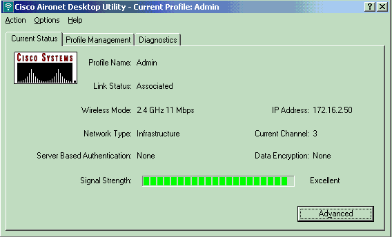
設定が期待通りに動作しているかを確認できます。SSID を Admin に設定した無線クライアント(管理ユーザ)は、VLAN 20 に接続できる必要があります。このユーザは、同じ VLAN の有線ネットワーク上の管理者ユーザにも接続できる必要があります。これを確認するには、管理者ユーザの無線クライアント プロファイルを起動します。
注:このドキュメントでは、プロファイルを設定するためにワイヤレスクライアントを設定する方法については説明していません。無線クライアント アダプタの設定方法についての詳細は、『クライアント アダプタの設定』を参照してください。
次のウィンドウを見ると、無線クライアントが AP に関連付けられいることがわかります。

クライアントが VLAN 10 に接続されているかどうかは、AP で show dot11 associations コマンドを発行する方法でも確認できます。
注:アウトプットインタープリタツール(登録ユーザ専用)(OIT)は、特定のshowコマンドをサポートしています。OIT を使用して、show コマンドの出力の分析を表示します。
AccessPoint#show dot11 associations

802.11 Client Stations on Dot11Radio0:

SSID [Admin] :

MAC Address    IP address      Device        Name            Parent         State
0040.96ac.e657 172.16.2.50     CB21AG/PI21AG Admin User      self           Assoc
AP で show vlans コマンドを発行して、AP に設定されている VLAN を表示できます。以下が一例です。
AccessPoint#show vlans

Virtual LAN ID:  2 (IEEE 802.1Q Encapsulation)

   vLAN Trunk Interfaces:  Dot11Radio0.2
FastEthernet0.2

This is configured as native Vlan for the following interface(s) :
Dot11Radio0
FastEthernet0

   Protocols Configured:   Address:              Received:        Transmitted:
        Bridging        Bridge Group 1               1380                 712
        Other                                          0                  63

   0 packets, 0 bytes input
   733 packets, 50641 bytes output
        Bridging        Bridge Group 1               1380                 712
        Other                                          0                  63

   1381 packets, 98016 bytes input
   42 packets, 12517 bytes output

Virtual LAN ID:  20 (IEEE 802.1Q Encapsulation)

   vLAN Trunk Interfaces:  Dot11Radio0.20
FastEthernet0.20

   Protocols Configured:   Address:              Received:        Transmitted:
        Bridging        Bridge Group 20               798                 622
        Other                                          0                  19

   247 packets, 25608 bytes input
   495 packets, 43585 bytes output
        Bridging        Bridge Group 20               798                 622
        Other                                          0                  19

   552 packets, 37536 bytes input
   148 packets, 21660 bytes output

Virtual LAN ID:  30 (IEEE 802.1Q Encapsulation)

   vLAN Trunk Interfaces:  Dot11Radio0.30
FastEthernet0.30

   Protocols Configured:   Address:              Received:        Transmitted:
        Bridging        Bridge Group 30               693                 609
        Other                                          0                  19

   106 packets, 13373 bytes input
   517 packets, 48029 bytes output
        Bridging        Bridge Group 30               693                 609
        Other                                          0                  19

   605 packets, 47531 bytes input
   112 packets, 15749 bytes output
ここで、無線管理者ユーザが、同じ VLAN で設定されている有線側の管理者ユーザに接続できるかどうかが確認できます。無線クライアントで ping コマンドを発行します。以下が一例です。
D:\>ping 172.16.2.60

Pinging 172.16.2.60 with 32 bytes of data:

Reply from 172.16.2.60: bytes=32 time<10ms TTL=255
Reply from 172.16.2.60: bytes=32 time<10ms TTL=255
Reply from 172.16.2.60: bytes=32 time<10ms TTL=255
Reply from 172.16.2.60: bytes=32 time<10ms TTL=255

Ping statistics for 172.16.2.60:
    Packets: Sent = 4, Received = 4, Lost = 0 (0% loss),
Approximate round trip times in milli-seconds:
    Minimum = 0ms, Maximum =  0ms, Average =  0ms
同様に、ゲスト ユーザが VLAN 30 に接続できるかどうかを確認します。ゲストの無線クライアントで ping コマンドを発行し、有線側にある Web サーバへの接続をテストします。以下が一例です。
D:\>ping 172.16.3.60

Pinging 172.16.3.60 with 32 bytes of data:

Reply from 172.16.3.60: bytes=32 time<10ms TTL=255
Reply from 172.16.3.60: bytes=32 time<10ms TTL=255
Reply from 172.16.3.60: bytes=32 time<10ms TTL=255
Reply from 172.16.3.60: bytes=32 time<10ms TTL=255

Ping statistics for 172.16.3.60:
    Packets: Sent = 4, Received = 4, Lost = 0 (0% loss),
Approximate round trip times in milli-seconds:
    Minimum = 0ms, Maximum =  0ms, Average =  0ms
トラブルシュート
このセクションは、設定のトラブルシューティングを行う際に参照してください。
トラブルシューティングの手順
設定のトラブルシューティングには、次の手順を実行します。
-
スイッチ ポートに設定され、AP に接続されたネイティブ VLAN が、AP のネイティブ VLAN に一致しているかどうかを確認します。
ネイティブ VLAN が一致しない場合、スイッチによる接続は得られません。
-
無線側に設定されているすべての VLAN が、トランクとして設定されたスイッチ ポートで許可されているかどうかを確認します。
デフォルトでは、すべての VLAN がトランク ポートで許可されます。
-
ネイティブ VLAN 以外のすべての VLAN で、bridge-group コマンドが設定されているかどうかを確認します。
ネイティブ VLAN として設定したサブインターフェイスには、ブリッジ グループを設定する必要はありません。このブリッジ グループは自動的にネイティブ サブインターフェイスに移され、BVI 1 へのリンクを確保します。これは、無線インターフェイスとイーサネット インターフェイスの両方を表します。
 注意:bridge-group コマンドを設定すると、これらのコマンドは自動でイネーブルになります。
bridge-group 10 subscriber-loop-control
bridge-group 10 block-unknown-source
no bridge-group 10 source-learning
no bridge-group 10 unicast-flooding
bridge-group 10 spanning-disabled
これは標準のデフォルト設定です。指示がない場合は、これらの設定は変更しないでください。これらのコマンドを削除すると、WLAN が期待通りに動作しなくなる可能性があります。
トラブルシューティングのためのコマンド
AP の設定のトラブルシューティングには次のコマンドも使用できます。
注:アウトプットインタープリタツール(登録ユーザ専用)(OIT)は、特定のshowコマンドをサポートしています。OIT を使用して、show コマンドの出力の分析を表示します。
-
show vlans
-
show vlans dot1q
-
show dot11 associations
Catalyst 2950 スイッチでは、設定のトラブルシューティングに次のコマンドを使用できます。
-
show vlans
-
show interface fastethernet x/x switchport
-
show interface fastethernet x/x trunk
ルータで、設定をトラブルシューティングするために、次のコマンドを発行してください。
-
debug ip dhcp server packet
-
show ip interface brief
SSID Admin での、クライアントへの正常な IP アドレス割り当ての出力を示します。
Router#debug ip dhcp server packet
*Nov 23 18:02:06.637: DHCPD: DHCPREQUEST received from client 0040.96ac.e657.

!--- Router receives the DHCP Request from the client

*Nov 23 18:02:06.637: DHCPD: No default domain to append - abort update
*Nov 23 18:02:06.637: DHCPD: Sending DHCPACK to client 0040.96ac.e657 (172.16.2.50).

!--- Router acknowledges the client's request

*Nov 23 18:02:06.637: DHCPD: creating ARP entry (172.16.2.2, 0040.96ac.e657).
*Nov 23 18:02:06.637: DHCPD: unicasting BOOTREPLY to client 0040.96ac.e657 (172.16.2.50).

!--- Router assigns ip address to the client from the VLAN 10 subnet
 注意:bridge-group コマンドを設定すると、これらのコマンドは自動でイネーブルになります。
 フィードバック