CatOS ソフトウェアが稼動する Catalyst 6500/6000 での IEEE 802.1x 認証の設定例
内容
概要
このドキュメントでは、ハイブリッド モード(スーパーバイザ エンジン上の CatOS と MSFC 上の Cisco IOS® ソフトウェア)で稼働する Catalyst 6500/6000 および Remote Authentication Dial-In User Service(RADIUS)サーバ上で、認証および VLAN 割り当てのために IEEE 802.1x を設定する方法について説明します。
前提条件
要件
このドキュメントの読者は次のトピックについての専門知識を有している必要があります。
使用するコンポーネント
このドキュメントの情報は、次のソフトウェアとハードウェアのバージョンに基づいています。
-
Catalyst 6500:スーパーバイザ エンジン上で CatOS ソフトウェア リリース 8.5(6)、MSFC 上で Cisco IOS ソフトウェア リリース 12.2(18)SXF を稼働させる
注:802.1xポートベース認証をサポートするには、CatOSリリース6.2以降が必要です。
注:ソフトウェアリリース7.2(2)より前では、802.1xホストが認証されると、NVRAMに設定されたVLANに参加します。ソフトウェア リリース 7.2(2) 以降の場合は、認証後、802.1x ホストは RADIUS サーバからその VLAN 割り当てを受信できます。
-
この例では、RADIUS サーバとして Cisco Secure Access Control Server(ACS)4.1 を使用します。
注:スイッチで802.1xを有効にする前に、RADIUSサーバを指定する必要があります。
-
802.1x 認証をサポートする PC クライアント
注:この例では、Microsoft Windows XPクライアントを使用しています。
このドキュメントの情報は、特定のラボ環境にあるデバイスに基づいて作成されました。このドキュメントで使用するすべてのデバイスは、初期(デフォルト)設定の状態から起動しています。対象のネットワークが実稼働中である場合には、どのようなコマンドについても、その潜在的な影響について確実に理解しておく必要があります。
表記法
ドキュメント表記の詳細は、『シスコ テクニカル ティップスの表記法』を参照してください。
背景説明
IEEE 802.1x 標準では、認証されていないデバイスが一般的にアクセス可能なポートを介して LAN に接続することを制限する、クライアントサーバ ベースのアクセス制御と認証プロトコルが定義されています。802.1x では、バーチャル アクセス ポイントを各ポートに 2 つ作成することで、ネットワーク アクセスが制御されます。片方のアクセス ポイントは制御されないポートであり、もう片方のアクセス ポイントは制御されたポートです。単一のポートを通過するすべてのトラフィックは、どちらのアクセス ポイントでも使用できます。802.1x では、スイッチ ポートに接続された各ユーザ デバイスが認証され、スイッチまたは LAN によって提供されるサービスが使用可能になる前にそのポートが VLAN に割り当てられます。802.1x アクセス制御では、デバイスが認証されるまで、そのデバイスが接続されているポートを通過する Extensible Authentication Protocol(EAP) over LAN(EAPOL)トラフィックのみが許可されます。認証に成功すると、通常のトラフィックはポートを通過できるようになります。
設定
このセクションでは、このドキュメントで説明する 802.1x 機能を設定するための情報を提供します。
注:このセクションで使用されているコマンドの詳細を調べるには、Command Lookup Tool(登録ユーザ専用)を参照してください。一部ツールについては、ゲスト登録のお客様にはアクセスできない場合がありますことをご了承ください。
設定には次の手順が必要です。
ネットワーク図
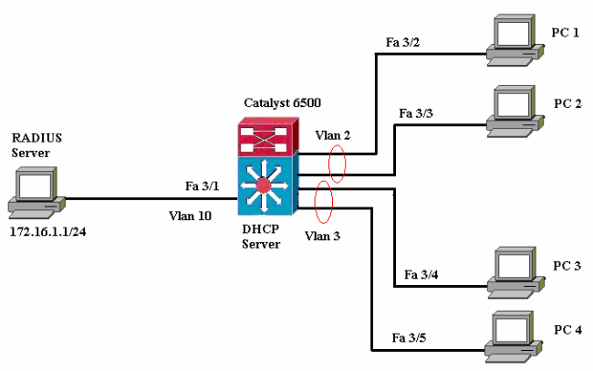
このドキュメントでは、次のネットワーク セットアップを使用します。
-
RADIUS サーバ:クライアントの実際の認証を実行します。RADIUS サーバは、クライアントの ID を検証し、クライアントが LAN およびスイッチ サービスにアクセスすることを承認されているかどうかをスイッチに通知します。ここで、RADIUS サーバの認証および VLAN 割り当ての設定が実行されます。
-
スイッチ:クライアントの認証ステータスに基づいて、ネットワークへの物理的なアクセスを制御します。スイッチは、クライアントと RADIUS サーバ間の中継要素(プロキシ)として動作し、クライアントに ID 情報を要求し、該当する情報を RADIUS サーバで確認し、応答をクライアントに返します。Catalyst 6500 スイッチは DHCP サーバとしても設定されます。802.1x 認証で Dynamic Host Configuration Protocol(DHCP)がサポートされているので、DHCP サーバは、認証済みユーザ ID を DHCP ディスカバリ プロセスに追加することにより、さまざまなクラスのエンド ユーザに IP アドレスを割り当てることができます。
-
クライアント:LAN およびスイッチのサービスに対するアクセスを要求し、スイッチからの要求に応答するデバイス(ワークステーション)。ここで、1 ~ 4 の PC は、認証済みネットワーク アクセスを要求するクライアントです。PC 1と2はVLAN 2に存在する同じログオン資格情報を使用します。同様に、PC 3と4はVLAN 3のログオン資格情報を使用します。PCクライアントは、DHCPサーバーからIPアドレスを取得するように構成されています。
注:この設定では、認証に失敗したクライアント、またはスイッチに接続している802.1x非対応のクライアントは、認証失敗とゲストVLAN機能を使用して未使用のVLAN(VLAN 4または5)に移動することで、ネットワークアクセスを拒否します。
Catalyst スイッチでの 802.1x 認証の設定
このスイッチ設定のサンプルには次のものが含まれます。
-
ファストイーサネット ポート上での 802.1x 認証および関連機能の有効化
-
ファストイーサネット ポート 3/1 の背後にある VLAN 10 への RADIUS サーバの接続
-
2 つの IP プール(一方は VLAN 2 内のクライアント用、他方は VLAN 3 内のクライアント用)に対する DHCP サーバの設定
-
認証後にクライアント間で接続を確立するためのインター VLAN ルーティング
802.1x 認証の設定方法に関するガイドラインについては、『認証の設定に関するガイドライン』を参照してください。
注:RADIUSサーバが常に認可ポートの背後に接続していることを確認します。
| Catalyst 6500 |
|---|
Console (enable) set system name Cat6K System name set. !--- Sets the hostname for the switch. Cat6K> (enable) set localuser user admin password cisco Added local user admin. Cat6K> (enable) set localuser authentication enable LocalUser authentication enabled !--- Uses local user authentication to access the switch. Cat6K> (enable) set vtp domain cisco VTP domain cisco modified !--- Domain name must be configured for VLAN configuration. Cat6K> (enable) set vlan 2 name VLAN2 VTP advertisements transmitting temporarily stopped, and will resume after the command finishes. Vlan 2 configuration successful !--- VLAN should be existing in the switch !--- for a successsful authentication. Cat6K> (enable) set vlan 3 name VLAN3 VTP advertisements transmitting temporarily stopped, and will resume after the command finishes. Vlan 3 configuration successful !--- VLAN names will be used in RADIUS server for VLAN assignment. Cat6K> (enable) set vlan 4 name AUTHFAIL_VLAN VTP advertisements transmitting temporarily stopped, and will resume after the command finishes. Vlan 4 configuration successful !--- A VLAN for non-802.1x capable hosts. Cat6K> (enable) set vlan 5 name GUEST_VLAN VTP advertisements transmitting temporarily stopped, and will resume after the command finishes. Vlan 4 configuration successful !--- A VLAN for failed authentication hosts. Cat6K> (enable) set vlan 10 name RADIUS_SERVER VTP advertisements transmitting temporarily stopped, and will resume after the command finishes. Vlan 10 configuration successful !--- This is a dedicated VLAN for the RADIUS Server. Cat6K> (enable) set interface sc0 10 172.16.1.2 255.255.255.0 Interface sc0 vlan set, IP address and netmask set. !--- Note: 802.1x authentication always uses the !--- sc0 interface as the identifier for the authenticator !--- when communicating with the RADIUS server. Cat6K> (enable) set vlan 10 3/1 VLAN 10 modified. VLAN 1 modified. VLAN Mod/Ports ---- ----------------------- 10 3/1 !--- Assigns port connecting to RADIUS server to VLAN 10. Cat6K> (enable) set radius server 172.16.1.1 primary 172.16.1.1 with auth-port 1812 acct-port 1813 added to radius server table as primary server. !--- Sets the IP address of the RADIUS server. Cat6K> (enable) set radius key cisco Radius key set to cisco !--- The key must match the key used on the RADIUS server. Cat6K> (enable) set dot1x system-auth-control enable dot1x system-auth-control enabled. Configured RADIUS servers will be used for dot1x authentication. !--- Globally enables 802.1x. !--- You must specify at least one RADIUS server before !--- you can enable 802.1x authentication on the switch. Cat6K> (enable) set port dot1x 3/2-48 port-control auto Port 3/2-48 dot1x port-control is set to auto. Trunking disabled for port 3/2-48 due to Dot1x feature. Spantree port fast start option enabled for port 3/2-48. !--- Enables 802.1x on all FastEthernet ports. !--- This disables trunking and enables portfast automatically. Cat6K> (enable) set port dot1x 3/2-48 auth-fail-vlan 4 Port 3/2-48 Auth Fail Vlan is set to 4 !--- Ports will be put in VLAN 4 after three !--- failed authentication attempts. Cat6K> (enable) set port dot1x 3/2-48 guest-vlan 5 Ports 3/2-48 Guest Vlan is set to 5 !--- Any non-802.1x capable host connecting or 802.1x !--- capable host failing to respond to the username and password !--- authentication requests from the Authenticator is placed in the !--- guest VLAN after 60 seconds. !--- Note: An authentication failure VLAN is independent !--- of the guest VLAN. However, the guest VLAN can be the same !--- VLAN as the authentication failure VLAN. If you do not want to !--- differentiate between the non-802.1x capable hosts and the !--- authentication failed hosts, you can configure both hosts to !--- the same VLAN (either a guest VLAN or an authentication failure VLAN). !--- For more information, refer to !--- Understanding How 802.1x Authentication for the Guest VLAN Works. Cat6K> (enable) switch console Trying Router-16... Connected to Router-16. Type ^C^C^C to switch back... !--- Transfers control to the routing module (MSFC). Router>enable Router#conf t Enter configuration commands, one per line. End with CNTL/Z. Router(config)#interface vlan 10 Router(config-if)#ip address 172.16.1.3 255.255.255.0 !--- This is used as the gateway address in RADIUS server. Router(config-if)#no shut Router(config-if)#interface vlan 2 Router(config-if)#ip address 172.16.2.1 255.255.255.0 Router(config-if)#no shut !--- This is the gateway address for clients in VLAN 2. Router(config-if)#interface vlan 3 Router(config-if)#ip address 172.16.3.1 255.255.255.0 Router(config-if)#no shut !--- This is the gateway address for clients in VLAN 3. Router(config-if)#exit Router(config)#ip dhcp pool vlan2_clients Router(dhcp-config)#network 172.16.2.0 255.255.255.0 Router(dhcp-config)#default-router 172.16.2.1 !--- This pool assigns ip address for clients in VLAN 2. Router(dhcp-config)#ip dhcp pool vlan3_clients Router(dhcp-config)#network 172.16.3.0 255.255.255.0 Router(dhcp-config)#default-router 172.16.3.1 !--- This pool assigns ip address for clients in VLAN 3. Router(dhcp-config)#exit Router(config)#ip dhcp excluded-address 172.16.2.1 Router(config)#ip dhcp excluded-address 172.16.3.1 !--- In order to go back to the Switching module, !--- enter Ctrl-C three times. Router# Router#^C Cat6K> (enable) Cat6K> (enable) show vlan VLAN Name Status IfIndex Mod/Ports, Vlans ---- ------------------ --------- ------- ------------------------ 1 default active 6 2/1-2 3/2-48 2 VLAN2 active 83 3 VLAN3 active 84 4 AUTHFAIL_VLAN active 85 5 GUEST_VLAN active 86 10 RADIUS_SERVER active 87 3/1 1002 fddi-default active 78 1003 token-ring-default active 81 1004 fddinet-default active 79 1005 trnet-default active 80 !--- Output suppressed. !--- All active ports will be in VLAN 1 (except 3/1) before authentication. Cat6K> (enable) show dot1x PAE Capability Authenticator Only Protocol Version 1 system-auth-control enabled max-req 2 quiet-period 60 seconds re-authperiod 3600 seconds server-timeout 30 seconds shutdown-timeout 300 seconds supp-timeout 30 seconds tx-period 30 seconds !--- Verifies dot1x status before authentication. Cat6K> (enable) |
RADIUS サーバの設定
RADIUSサーバには172.16.1.1/24のスタティックIPアドレスが設定されています。AAAクライアント用にRADIUSサーバを設定するには、次の手順を実行します。
-
AAA クライアントを設定するために、ACS 管理ウィンドウで Network Configuration をクリックします。
-
AAA クライアントのセクションの下部にある [Add Entry] をクリックします。

-
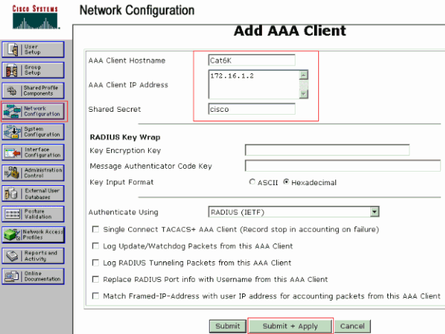
次のように、AAA クライアント ホスト名、IP アドレス、共有秘密鍵、および認証タイプを設定します。
-
AAA クライアント ホスト名 = スイッチ ホスト名(Cat6K)
-
AAA クライアントの IP アドレス = スイッチの管理インターフェイス(sc0)の IP アドレス(172.16.1.2)
-
共有秘密鍵 = スイッチで設定されている Radius キー(cisco)
-
Authenticate Using = RADIUS IETF
注:正しく操作するには、AAAクライアントとACSで共有秘密キーが同一である必要があります。キーの大文字と小文字は区別されます。
-
-
これらの変更を有効にするには、次の例に示すように Submit + Apply をクリックします。
RADIUS サーバの認証、VLAN、および IP アドレスの割り当てを設定するには、後述のステップを実行します。
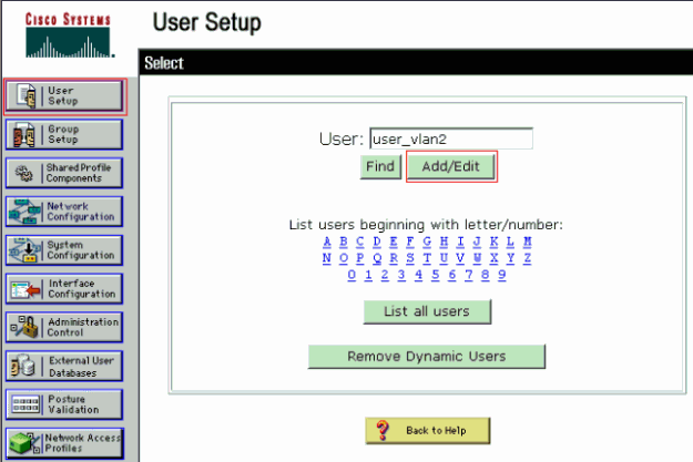
VLAN 2に接続するクライアントとVLAN 3に接続するクライアントに対して、2つのユーザ名を個別に作成する必要があります。ここでは、VLAN 2に接続するクライアント用のユーザuser_vlan2と、VLAN 3に接続するクライアント用user_vlan3が作成されます。
注:ここでは、VLAN 2のみに接続するクライアントのユーザ設定を示します。VLAN 3 に接続するユーザの場合も、同じ手順を実行してください。
-
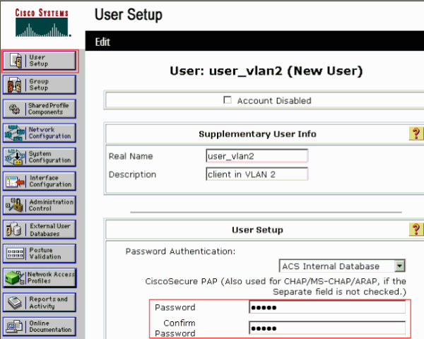
ユーザを追加し、設定するために User Setup をクリックし、ユーザ名とパスワードを定義します。
-
Assigned by AAA client pool としてクライアント IP アドレス割り当てを定義します。VLAN 2 クライアントのスイッチ上で設定された IP アドレス プールの名前を入力します。
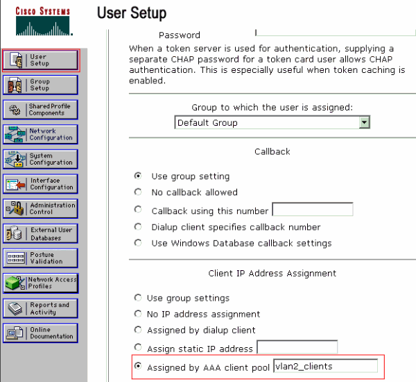
注:このオプションを選択して、AAAクライアントのIPプール名を入力します。このユーザがAAAクライアントに設定されたIPアドレスプールによって割り当てられたIPアドレスを持っている場合にのみ使用します。
-
Internet Engineering Task Force(IETF)の属性 64 および 65 を定義します。
この例のように、値のタグには 1 を設定してください。Catalystでは、1以外のタグは無視されます。ユーザを特定のVLANに割り当てるには、対応するVLAN名を使用して属性81を定義する必要があります。
注:VLAN名は、スイッチで設定されているものと完全に同じである必要があります。
注:CatOSではVLAN番号に基づくVLAN割り当てはサポートされていません。
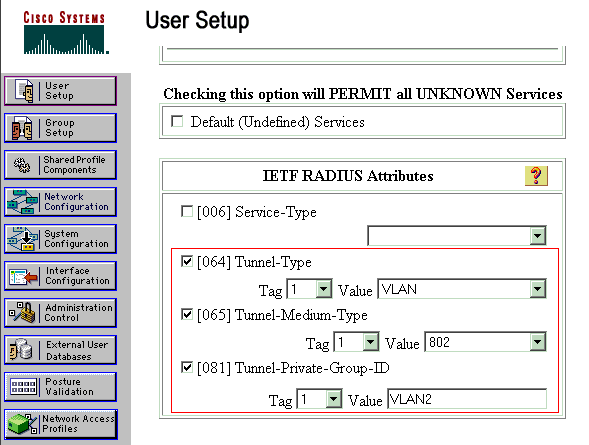
これらの IETF 属性の詳細については、『RFC 2868:IETF属性の詳細については、『RADIUS Attributes for Tunnel Protocol Support
 』を参照してください。
注:ACSサーバの初期設定では、IETF RADIUS属性がユーザ設定で表示されない場合があります。IETF 属性を有効にするために、ユーザ設定画面で Interface configuration > RADIUS (IETF) の順に選択します。次に、[User and Group] 列で属性 64、65、および 81 にチェックを付けます。
802.1x 認証を使用するための PC クライアントの設定
この設定例は、Microsoft Windows XP の Extensible Authentication Protocol(EAP)over LAN(EAPOL)クライアント固有のものです。次のステップを実行します。
-
[スタート] > [コントロールパネル] > [ネットワーク接続] の順にクリックし、[ローカルエリア接続] を右クリックして [プロパティ] を選択します。
-
General タブで、Show icon in notification area when connected にチェックを付けます。
-
[Authentication] タブで、[Enable IEEE 802.1x authentication for this network] にチェックを付けます。
-
次の例のように、EAP の種類に [MD5-Challenge] を選択します。
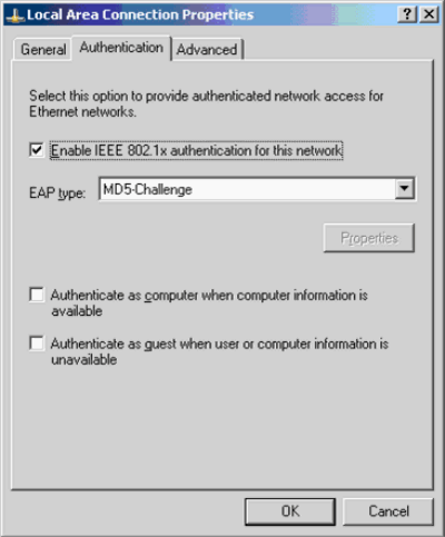
次の手順に従って、クライアントが DHCP サーバから IP アドレスを取得できるように設定します。
-
[スタート] > [コントロールパネル] > [ネットワーク接続] の順にクリックし、[ローカルエリア接続] を右クリックして [プロパティ] を選択します。
-
[General] タブで、[Internet Protocol (TCP/IP)] をクリックし、[Properties]をクリックします。
-
[Obtain an IP address automatically] を選択します。
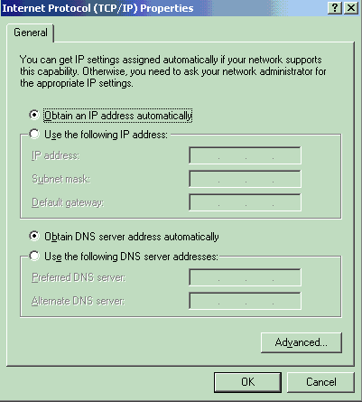
確認
ここでは、設定が正常に機能しているかどうかを確認します。
アウトプット インタープリタ ツール(登録ユーザ専用)(OIT)は、特定の show コマンドをサポートします。OIT を使用して、show コマンドの出力の分析を表示します。
PC クライアント
設定が正しく完了すると、PCクライアントにユーザ名とパスワードを入力するためのポップアッププロンプトが表示されます。
-
次の例で示すプロンプトをクリックします。
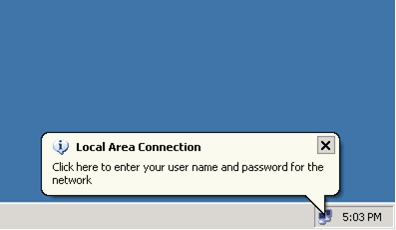
ユーザ名とパスワードの入力ウィンドウが表示されます。
-
[Username ] と [Password] を入力します。
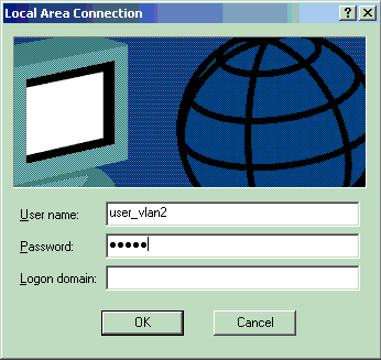
注:PC 1と2で、VLAN 2のユーザクレデンシャルを入力します。PC 3 と 4 で、VLAN 3 ユーザのクレデンシャルを入力します。
-
エラー メッセージが表示されなければ、ネットワーク リソースにアクセスしたり、ping コマンドを発行したりするなど、通常の方法で接続を確認します。次の図は PC 1 からの出力であり、PC 4 に対する ping が成功したことを示しています。
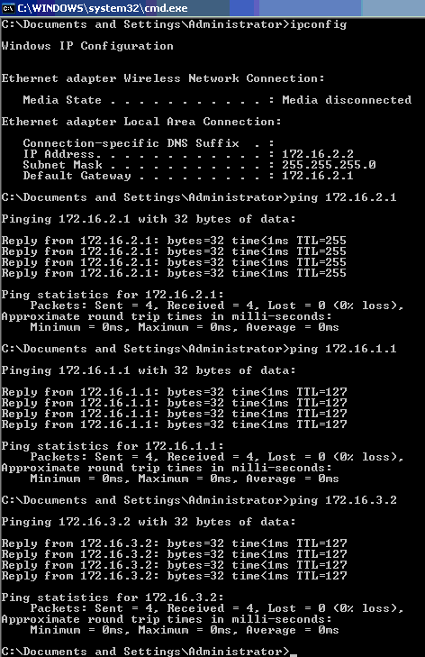
次のエラーが表示された場合は、ユーザ名とパスワードが正しく入力されているかどうかを確認します。

Catalyst 6500
パスワードとユーザ名が正しいと思われる場合は、スイッチの802.1xポートの状態を確認します。
-
authorized を示すポート状態を探します。
Cat6K> (enable) show port dot1x 3/1-5

Port  Auth-State          BEnd-State Port-Control        Port-Status
----- ------------------- ---------- ------------------- -------------
 3/1  force-authorized   idle       force-authorized    authorized

!--- This is the port to which RADIUS server is connected.

 3/2  authenticated       idle       auto                authorized
 3/3  authenticated       idle       auto                authorized
 3/4  authenticated       idle       auto                authorized
 3/5  authenticated       idle       auto                authorized

Port  Port-Mode     Re-authentication    Shutdown-timeout
----- ------------- -----------------    ----------------
 3/1  SingleAuth    disabled             disabled
 3/2  SingleAuth    disabled             disabled
 3/3  SingleAuth    disabled             disabled
 3/4  SingleAuth    disabled             disabled
 3/5  SingleAuth    disabled             disabled
認証に成功した後、VLAN ステータスを確認します。
Cat6K> (enable) show vlan VLAN Name Status IfIndex Mod/Ports, Vlans ---- -------------------------------- --------- ------- ------------------------ 1 default active 6 2/1-2 3/6-48 2 VLAN2 active 83 3/2-3 3 VLAN3 active 84 3/4-5 4 AUTHFAIL_VLAN active 85 5 GUEST_VLAN active 86 10 RADIUS_SERVER active 87 3/1 1002 fddi-default active 78 1003 token-ring-default active 81 1004 fddinet-default active 79 1005 trnet-default active 80 !--- Output suppressed. -
認証に成功した後のルーティング モジュール(MSFC)からの DHCP バインディング ステータスを確認します。
Router#show ip dhcp binding
IP address       Hardware address        Lease expiration        Type
172.16.2.2       0100.1636.3333.9c       Feb 14 2007 03:00 AM    Automatic
172.16.2.3       0100.166F.3CA3.42       Feb 14 2007 03:03 AM    Automatic
172.16.3.2       0100.145e.945f.99       Feb 14 2007 03:05 AM    Automatic
172.16.3.3       0100.1185.8D9A.F9       Feb 14 2007 03:07 AM    Automatic
トラブルシュート
現在、この設定に関する特定のトラブルシューティング情報はありません。
関連情報
更新履歴
| 改定 | 発行日 | コメント |
|---|---|---|
1.0 |
19-Mar-2007 |
初版 |
 フィードバック