アクティブ/バックアップまたはアクティブ/アクティブシナリオ用の包括SIGトンネルの設定
ダウンロード オプション
偏向のない言語
この製品のドキュメントセットは、偏向のない言語を使用するように配慮されています。このドキュメントセットでの偏向のない言語とは、年齢、障害、性別、人種的アイデンティティ、民族的アイデンティティ、性的指向、社会経済的地位、およびインターセクショナリティに基づく差別を意味しない言語として定義されています。製品ソフトウェアのユーザインターフェイスにハードコードされている言語、RFP のドキュメントに基づいて使用されている言語、または参照されているサードパーティ製品で使用されている言語によりドキュメントに例外が存在する場合があります。シスコのインクルーシブ ランゲージの取り組みの詳細は、こちらをご覧ください。
翻訳について
シスコは世界中のユーザにそれぞれの言語でサポート コンテンツを提供するために、機械と人による翻訳を組み合わせて、本ドキュメントを翻訳しています。ただし、最高度の機械翻訳であっても、専門家による翻訳のような正確性は確保されません。シスコは、これら翻訳の正確性について法的責任を負いません。原典である英語版(リンクからアクセス可能)もあわせて参照することを推奨します。
内容
はじめに
このドキュメントでは、 Cisco Umbrella Secure Internet Gateway (SIG) IPSecを使用したトンネルを Active/Active と Active/Standbyを参照。
前提条件
要件
次の項目に関する知識があることが推奨されます。
- 『シスコ
Umbrella - IPSecネゴシエーション
-
Cisco Software-Defined Wide Area Network(SD-WAN)
使用するコンポーネント
このドキュメントの情報は、次のソフトウェアとハードウェアのバージョンに基づいています。
- Cisco vManageバージョン20.4.2
- Cisco WANエッジルータC1117-4PW*バージョン17.4.2
このドキュメントの情報は、特定のラボ環境にあるデバイスに基づいて作成されました。このドキュメントで使用するすべてのデバイスは、クリアな(デフォルト)設定で作業を開始しています。本稼働中のネットワークでは、各コマンドによって起こる可能性がある影響を十分確認してください。
背景説明
Cisco Umbrella SIGの概要
『シスコ Umbrella は、重要な機能を1つにまとめるクラウド型のセキュリティサービスです。
Umbrella セキュアなWebゲートウェイ、DNSセキュリティ、クラウド提供のファイアウォール、クラウドアクセスセキュリティブローカ機能、および脅威インテリジェンスを統合
詳細な検査と制御により、アクセプタブルユースWebポリシーに準拠し、インターネットの脅威から保護します。
SD-WANルータは、ほとんどの処理を行うSecure Internet Gateway(SIG)と統合して、企業トラフィックを保護できます。
SIGが設定されると、ルートまたはポリシーに基づくすべてのクライアントトラフィックがSIGに転送されます。
Umbrella SIGトンネル帯域幅の制限
各IPsec IKEv2トンネルを Umbrella ヘッドエンドは約250 Mbpsに制限されているため、複数のトンネルを作成してトラフィックのロードバランシングを行う場合は、より高い帯域幅が必要になった場合に備えてこのような制限を克服します。
最大4 High Availability トンネルペアを作成できます。
Cisco Umbrellaポータル情報の入手
SIG統合に進むには、 Umbrella SIG Essentialsパッケージのアカウントが必要です。
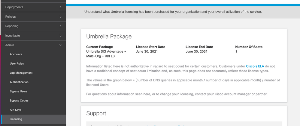
キーと秘密キーの取得
キーと秘密キーは、 Umbrella Management API KEY (このキーは「レガシーキー」の下にあります)。秘密キーを忘れた場合、または秘密キーを保存しなかった場合は、refreshをクリックします。
注意:更新ボタンをクリックすると、すべてのデバイスでこれらのキーの更新が必要になります。使用中のデバイスがある場合は、更新はお勧めできません。

組織IDの取得
組織IDは、にログインすると簡単に取得できます Umbrella ブラウザのアドレスバーからアクセスします。

アクティブ/バックアップシナリオでの包括SIGトンネルの作成
注:ECMPを使用したIPsec/GREトンネルルーティングおよびロードバランシング:この機能はvManage 20.4.1以降で使用可能で、SIGテンプレートを使用してアプリケーショントラフィックをシスコに誘導できます Umbrella またはサードパーティのSIGプロバイダー
注:Zscaler自動プロビジョニングのサポート:この機能はvManage 20.5.1以降で使用できます。この機能は、ZscalerパートナーAPIクレデンシャルを使用して、Cisco SD-WANルータからZscalerへのトンネルのプロビジョニングを自動化します。
SIG自動トンネルを設定するには、いくつかのテンプレートを作成または更新する必要があります。
- SIG Credentials機能テンプレートを作成します。
- SIGトンネルをリンクするために2つのループバックインターフェイスを作成します(複数のインターフェイスにのみ適用可能)
Active同時にトンネルを確立できますActive/Activeシナリオ)。 - SIG機能テンプレートを作成します。
- サービス側のVPNテンプレートを編集して
Service Routeを参照。
注:UDP 4500および500ポートが任意のアップストリームデバイスから許可されていることを確認します。
テンプレートの設定は、 Active/Backup および Active/Active 両方のシナリオについて個別に説明し、公開するシナリオ。
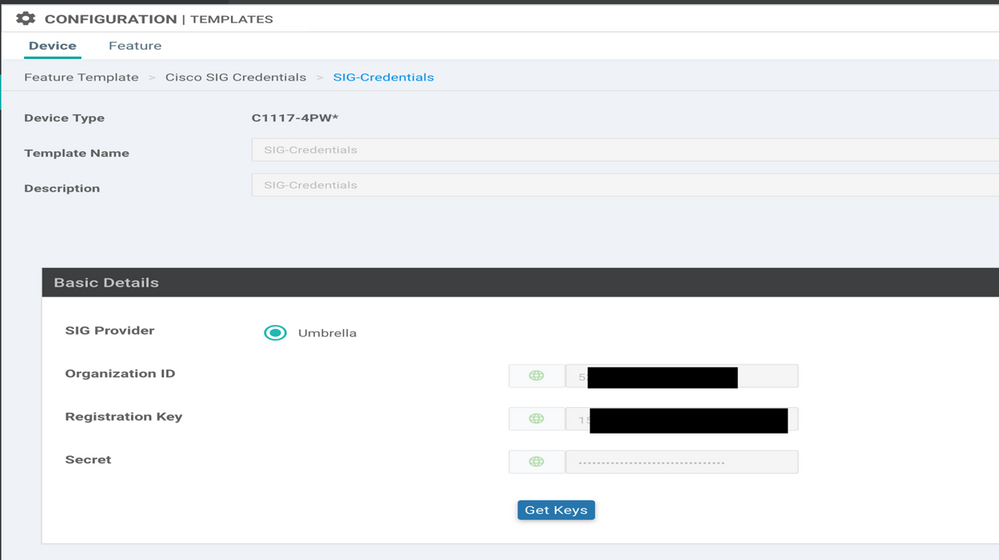
ステップ 1:SIG Credentials機能テンプレートを作成します。
機能テンプレートに移動し、 Editを参照。

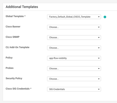
~のセクションの下で Additional templates、クリック Cisco SIG Credentialsを参照。このオプションを図に示します。
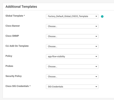
テンプレートに名前と説明を付けます。
ステップ 2:SIG機能テンプレートを作成します。
機能テンプレートに移動し、セクションの下で Transport & Management VPN Cisco Secure Internet Gateway機能テンプレートを選択します。
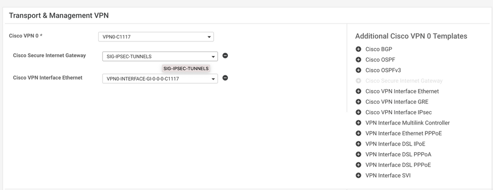
テンプレートに名前と説明を付けます。
ステップ 3:Primary TunnelにSIG Providerを選択します。
クリック Add Tunnelを参照。

基本的な詳細を設定し、 Data-Center as Primaryをクリックし、 Addを参照。
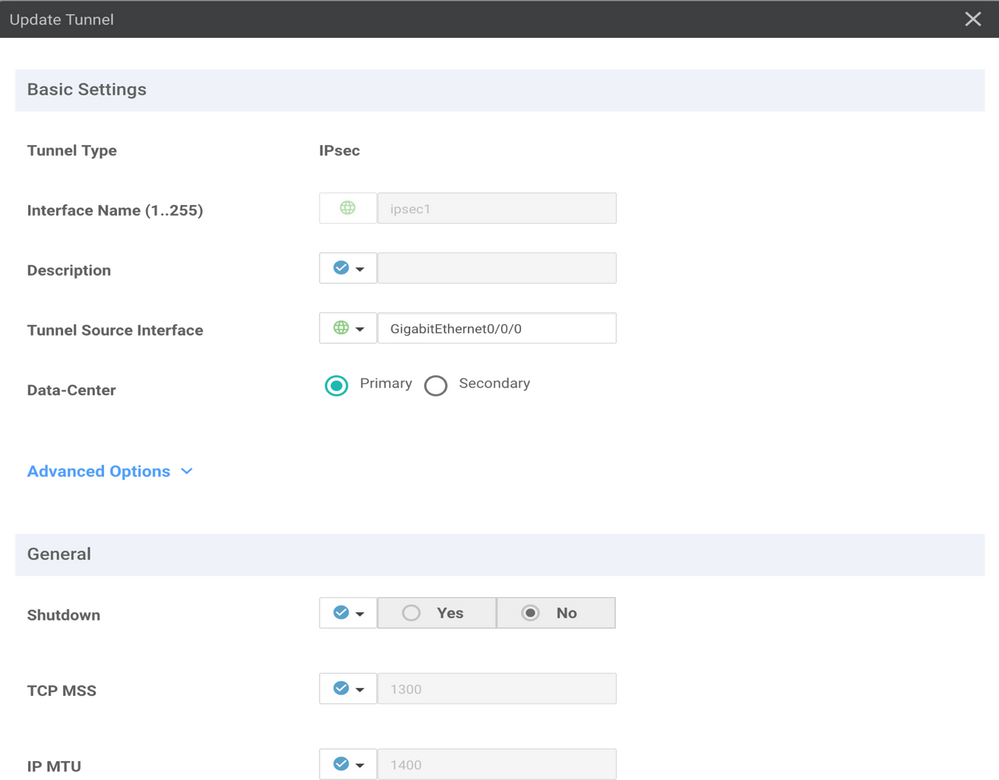
ステップ4:セカンダリトンネルを追加します。
2番目のトンネル設定を追加するには、 Data-Center as Secondary 今度は、インターフェイス名をipsec2に設定します。
vManage設定は次のように表示されます。

ステップ 5:ハイアベイラビリティペアを1つ作成します。
内部 High Availability セクションで、ipsec1をActiveとして選択し、ipsec2トンネルをBackupとして選択します。

注:最大4 High Availability トンネルペアと最大4つのアクティブトンネルを同時に作成できます。
手順 6:サービスルートを挿入するためのサービス側VPNテンプレートの編集
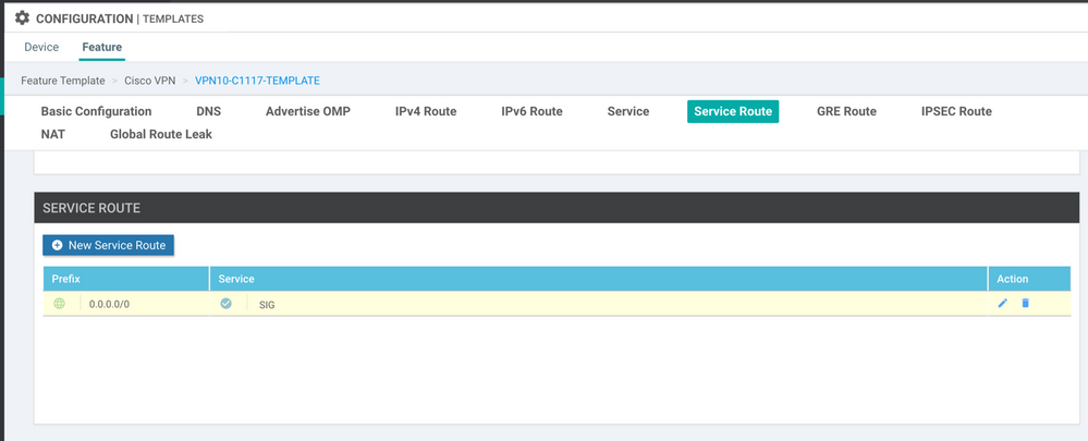
に移動します。 Service VPN セクション内および Service VPN テンプレート、セクションに移動 Service Route 0.0.0.0をSIG Service Routeを参照。このドキュメントでは、VRF/VPN 10を使用します。

次に示すように、0.0.0.0 SIGルートが表示されます。
注:サービストラフィックが実際に発信されるようにするには、WANインターフェイスでNATを設定する必要があります。
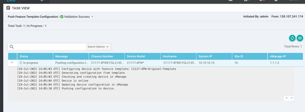
このテンプレートをデバイスに接続し、設定をプッシュします。
アクティブ/バックアップシナリオ用のWANエッジルータ設定
system
   host-name             <HOSTNAME>
   system-ip             <SYSTEM-IP>
   overlay-id            1
   site-id               <SITE-ID>
   sp-organization-name  <ORG-NAME>
   organization-name     <SP-ORG-NAME>
   vbond <VBOND-IP> port 12346
  !
  secure-internet-gateway
   umbrella org-id <UMBRELLA-ORG-ID>
   umbrella api-key <UMBRELLA-API-KEY-INFO>
   umbrella api-secret <UMBRELLA-SECRET-INFO>
  !
  sdwan
   service sig vrf global
    ha-pairs
     interface-pair Tunnel100001 active-interface-weight 1 Tunnel100002 backup-interface-weight 1
    !
   !
   interface GigabitEthernet0/0/0
    tunnel-interface
     encapsulation ipsec weight 1
     no border
     color biz-internet
     no last-resort-circuit
     no low-bandwidth-link
     no vbond-as-stun-server
     vmanage-connection-preference 5
     port-hop
     carrier                       default
     nat-refresh-interval          5
     hello-interval                1000
     hello-tolerance               12
     allow-service all
     no allow-service bgp
     allow-service dhcp
     allow-service dns
     allow-service icmp
     no allow-service sshd
     no allow-service netconf
     no allow-service ntp
     no allow-service ospf
     no allow-service stun
     allow-service https
     no allow-service snmp
     no allow-service bfd
    exit
   exit
   interface Tunnel100001
    tunnel-options tunnel-set secure-internet-gateway-umbrella tunnel-dc-preference primary-dc source-interface GigabitEthernet0/0/0
   exit
   interface Tunnel100002
    tunnel-options tunnel-set secure-internet-gateway-umbrella tunnel-dc-preference secondary-dc source-interface GigabitEthernet0/0/0
   exit
   appqoe
    no tcpopt enable
   !
  security
   ipsec
    rekey               86400
    replay-window       512
    authentication-type sha1-hmac ah-sha1-hmac
   !
  !
  service tcp-keepalives-in
  service tcp-keepalives-out
  no service tcp-small-servers
  no service udp-small-servers
  hostname <DEVICE-HOSTNAME>
  username admin privilege 15 secret 9 <SECRET-PASSWORD>
  vrf definition 10
   rd 1:10
   address-family ipv4
    route-target export 1:10
    route-target import 1:10
    exit-address-family
   !
   address-family ipv6
    exit-address-family
   !
  !
  vrf definition Mgmt-intf
   description Transport VPN
   rd          1:512
   address-family ipv4
    route-target export 1:512
    route-target import 1:512
    exit-address-family
   !
   address-family ipv6
    exit-address-family
   !
  !
  ip sdwan route vrf 10 0.0.0.0/0 service sig
  no ip http server
  no ip http secure-server
  no ip http ctc authentication
  ip nat settings central-policy
  vlan 10
  exit
  interface GigabitEthernet0/0/0
   no shutdown
   arp timeout 1200
   ip address dhcp client-id GigabitEthernet0/0/0
   no ip redirects
   ip dhcp client default-router distance 1
   ip mtu    1500
   load-interval 30
   mtu           1500
  exit
  interface GigabitEthernet0/1/0
   switchport access vlan 10
   switchport mode access
   no shutdown
  exit
  interface GigabitEthernet0/1/1
   switchport mode access
   no shutdown
  exit
  interface Vlan10
   no shutdown
   arp timeout 1200
   vrf forwarding 10
   ip address <VLAN-IP-ADDRESS> <MASK>
   ip mtu 1500
   ip nbar protocol-discovery
  exit
  interface Tunnel0
   no shutdown
   ip unnumbered GigabitEthernet0/0/0
   no ip redirects
   ipv6 unnumbered GigabitEthernet0/0/0
   no ipv6 redirects
   tunnel source GigabitEthernet0/0/0
   tunnel mode sdwan
  exit
  interface Tunnel100001
   no shutdown
   ip unnumbered GigabitEthernet0/0/0
   ip mtu     1400
   tunnel source GigabitEthernet0/0/0
   tunnel destination dynamic
   tunnel mode ipsec ipv4
   tunnel protection ipsec profile if-ipsec1-ipsec-profile
   tunnel vrf multiplexing
  exit
  interface Tunnel100002
   no shutdown
   ip unnumbered GigabitEthernet0/0/0
   ip mtu     1400
   tunnel source GigabitEthernet0/0/0
   tunnel destination dynamic
   tunnel mode ipsec ipv4
   tunnel protection ipsec profile if-ipsec2-ipsec-profile
   tunnel vrf multiplexing
  exit
  clock timezone UTC 0 0
  logging persistent size 104857600 filesize 10485760
  logging buffered 512000
  logging console
  no logging rate-limit
  aaa authentication log in default local
  aaa authorization exec default local
  aaa session-id common
  mac address-table aging-time 300
  no crypto ikev2 diagnose error
  crypto ikev2 policy policy1-global
   proposal p1-global
  !
  crypto ikev2 profile if-ipsec1-ikev2-profile
   no config-exchange request
   dpd 10 3 on-demand
   dynamic
   lifetime 86400
  !
  crypto ikev2 profile if-ipsec2-ikev2-profile
   no config-exchange request
   dpd 10 3 on-demand
   dynamic
   lifetime 86400
  !
  crypto ikev2 proposal p1-global
   encryption aes-cbc-128 aes-cbc-256
   group 14 15 16
   integrity sha1 sha256 sha384 sha512
  !
  crypto ipsec transform-set if-ipsec1-ikev2-transform esp-gcm 256
   mode tunnel
  !
  crypto ipsec transform-set if-ipsec2-ikev2-transform esp-gcm 256
   mode tunnel
  !
  crypto ipsec profile if-ipsec1-ipsec-profile
   set ikev2-profile if-ipsec1-ikev2-profile
   set transform-set if-ipsec1-ikev2-transform
   set security-association lifetime kilobytes disable
   set security-association lifetime seconds 3600
   set security-association replay window-size 512
  !
  crypto ipsec profile if-ipsec2-ipsec-profile
   set ikev2-profile if-ipsec2-ikev2-profile
   set transform-set if-ipsec2-ikev2-transform
   set security-association lifetime kilobytes disable
   set security-association lifetime seconds 3600
   set security-association replay window-size 512
  !
  no crypto isakmp diagnose error
  no network-clock revertive
アクティブ/アクティブシナリオでの包括SIGトンネルの作成
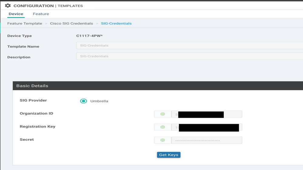
ステップ 1:SIG Credentials機能テンプレートを作成します。
機能テンプレートに移動し、 Edit

~のセクションの下で Additional templates、選択 Cisco SIG Credentialsを参照。オプションが図に示されています。
テンプレートに名前と説明を付けます。
ステップ 2:SIGトンネルをリンクする2つのループバックインターフェイスを作成します。
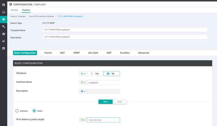
注:アクティブなモードで設定されているSIGトンネルごとにループバックインターフェイスを作成します。これは、各トンネルに一意のIKE IDが必要であるためです。
注:このシナリオはアクティブ/アクティブであるため、2つのループバックが作成されます。
ループバックのインターフェイス名とIPv4アドレスを設定します。
注:ループバックに設定されているIPアドレスはダミーアドレスです。
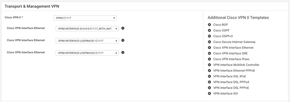
2つ目のループバックテンプレートを作成し、デバイステンプレートに接続します。デバイステンプレートには、次の2つのループバックテンプレートが接続されている必要があります。
ステップ 3:SIG機能テンプレートを作成します。
SIG機能テンプレートに移動し、 Transport & Management VPN 選択 Cisco Secure Internet Gateway
ステップ 4:Primary TunnelのSIG Providerを選択します。
クリック Add Tunnelを参照。

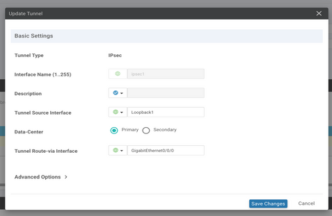
基本的な詳細を設定し、 Data-Center as Primaryを参照。
注:Tunnel Source Interfaceパラメータはループバック(このドキュメントのLoopback1)で、Tunnel Route-viaインターフェイスとして物理インターフェイス(このドキュメントのGigabitEthernet0/0/0)です。
ステップ5:セカンダリトンネルを追加します。
2番目のトンネル設定を追加するには、 Data-Center as Primary インターフェイス名もipsec2です。
vManage設定は次のように表示されます。

手順 6:2つのハイアベイラビリティペアを作成します。
内部 High Availability セクション、2つ作成 High Availability ペア。
- 最初のHAペアで、ipsec1をアクティブとして選択し、
Noneバックアップ用。 - 2番目のHAペアで、ipsec2をアクティブ選択として選択します
Noneバックアップ用です
のvManage設定 High Availability 次のように表示されます。

デバイステンプレートには、2つのループバックテンプレートとSIG機能テンプレートが添付されています。
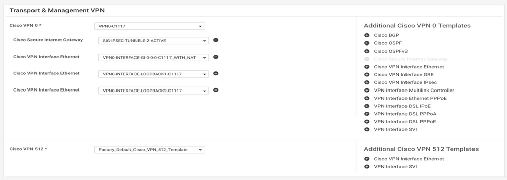
手順 7:サービスルートを挿入するためのサービス側VPNテンプレートの編集
に移動します。 Service VPN セクションに移動し、サービステンプレートのVPN内で Service Route 0.0.0.0をSIGService Route

次に示すように、0.0.0.0 SIGルートが表示されます。
注:サービストラフィックが実際に発信されるようにするには、WANインターフェイスでNATを設定する必要があります。
このテンプレートをデバイスに接続し、設定をプッシュします。
アクティブ/アクティブシナリオ用のWANエッジルータの設定
system
 host-name <HOSTNAME>
 system-ip <SYSTEM-IP>
 overlay-id 1
 site-id <SITE-ID>
 sp-organization-name <ORG-NAME>
 organization-name <SP-ORG-NAME>
 vbond <VBOND-IP> port 12346
!
secure-internet-gateway
 umbrella org-id <UMBRELLA-ORG-ID>
 umbrella api-key <UMBRELLA-API-KEY-INFO>
 umbrella api-secret <UMBRELLA-SECRET-INFO>
!
sdwan
 service sig vrf global
  ha-pairs
  interface-pair Tunnel100001 active-interface-weight 1 None backup-interface-weight 1
  interface-pair Tunnel100002 active-interface-weight 1 None backup-interface-weight 1
!
interface GigabitEthernet0/0/0
 tunnel-interface
  encapsulation ipsec weight 1
  no border
  color biz-internet
  no last-resort-circuit
  no low-bandwidth-link
  no vbond-as-stun-server
  vmanage-connection-preference 5
  port-hop
  carrier default
  nat-refresh-interval 5
  hello-interval 1000
  hello-tolerance 12
  allow-service all
  no allow-service bgp
  allow-service dhcp
  allow-service dns
  allow-service icmp
  no allow-service sshd
  no allow-service netconf
  no allow-service ntp
  no allow-service ospf
  no allow-service stun
  allow-service https
  no allow-service snmp
  no allow-service bfd
 exit
exit
interface Tunnel100001
 tunnel-options tunnel-set secure-internet-gateway-umbrella tunnel-dc-preference primary-dc source-interface Loopback1
exit
interface Tunnel100002
 tunnel-options tunnel-set secure-internet-gateway-umbrella tunnel-dc-preference primary-dc source-interface Loopback2
exit
appqoe
no tcpopt enable
!
security
ipsec
rekey 86400
replay-window 512
authentication-type sha1-hmac ah-sha1-hmac
!
!
service tcp-keepalives-in
service tcp-keepalives-out
no service tcp-small-servers
no service udp-small-servers
hostname <DEVICE HOSTNAME>
username admin privilege 15 secret 9 <secret-password>
vrf definition 10
 rd 1:10
 address-family ipv4
 route-target export 1:10
 route-target import 1:10
 exit-address-family
!
 address-family ipv6
 exit-address-family
!
!
vrf definition Mgmt-intf
 description Transport VPN
 rd 1:512
 address-family ipv4
 route-target export 1:512
 route-target import 1:512
 exit-address-family
!
 address-family ipv6
 exit-address-family
!
no ip source-route
ip sdwan route vrf 10 0.0.0.0/0 service sig
ip nat inside source list nat-dia-vpn-hop-access-list interface GigabitEthernet0/0/0 overload
ip nat translation tcp-timeout 3600
ip nat translation udp-timeout 60
ip nat settings central-policy
vlan 10
exit
interface GigabitEthernet0/0/0
 no shutdown
 arp timeout 1200
 ip address dhcp client-id GigabitEthernet0/0/0
 no ip redirects
 ip dhcp client default-router distance 1
 ip mtu 1500
 ip nat outside
 load-interval 30
 mtu 1500
exit
interface GigabitEthernet0/1/0
 switchport access vlan 10
 switchport mode access
 no shutdown
 exit
interface Loopback1
 no shutdown
 arp timeout 1200
 ip address 10.20.20.1 255.255.255.255
 ip mtu 1500
 exit
interface Loopback2
 no shutdown
 arp timeout 1200
 ip address 10.10.10.1 255.255.255.255
 ip mtu 1500
 exit
interface Vlan10
 no shutdown
 arp timeout 1200
 vrf forwarding 10
 ip address 10.1.1.1 255.255.255.252
 ip mtu 1500
 ip nbar protocol-discovery
exit
interface Tunnel0
 no shutdown
 ip unnumbered GigabitEthernet0/0/0
 no ip redirects
 ipv6 unnumbered GigabitEthernet0/0/0
 no ipv6 redirects
 tunnel source GigabitEthernet0/0/0
 tunnel mode sdwan
exit
interface Tunnel100001
 no shutdown
 ip unnumbered Loopback1
 ip mtu 1400
 tunnel source Loopback1
 tunnel destination dynamic
 tunnel mode ipsec ipv4
 tunnel protection ipsec profile if-ipsec1-ipsec-profile
 tunnel vrf multiplexing
 tunnel route-via GigabitEthernet0/0/0 mandatory
exit
interface Tunnel100002
 no shutdown
 ip unnumbered Loopback2
 ip mtu 1400
 tunnel source Loopback2
 tunnel destination dynamic
 tunnel mode ipsec ipv4
 tunnel protection ipsec profile if-ipsec2-ipsec-profile
 tunnel vrf multiplexing
 tunnel route-via GigabitEthernet0/0/0 mandatory
exit
clock timezone UTC 0 0
logging persistent size 104857600 filesize 10485760
logging buffered 512000
logging console
no logging rate-limit
aaa authentication log in default local
aaa authorization exec default local
aaa session-id common
mac address-table aging-time 300
no crypto ikev2 diagnose error
crypto ikev2 policy policy1-global
proposal p1-global
!
crypto ikev2 profile if-ipsec1-ikev2-profile
 no config-exchange request
 dpd 10 3 on-demand
 dynamic
 lifetime 86400
!
crypto ikev2 profile if-ipsec2-ikev2-profile
 no config-exchange request
 dpd 10 3 on-demand
 dynamic
 lifetime 86400
!
crypto ikev2 proposal p1-global
 encryption aes-cbc-128 aes-cbc-256
 group 14 15 16
 integrity sha1 sha256 sha384 sha512
!
crypto ipsec transform-set if-ipsec1-ikev2-transform esp-gcm 256
 mode tunnel
!
crypto ipsec transform-set if-ipsec2-ikev2-transform esp-gcm 256
 mode tunnel
!
crypto ipsec profile if-ipsec1-ipsec-profile
 set ikev2-profile if-ipsec1-ikev2-profile
 set transform-set if-ipsec1-ikev2-transform
 set security-association lifetime kilobytes disable
 set security-association lifetime seconds 3600
 set security-association replay window-size 512
!
crypto ipsec profile if-ipsec2-ipsec-profile
 set ikev2-profile if-ipsec2-ikev2-profile
 set transform-set if-ipsec2-ikev2-transform
 set security-association lifetime kilobytes disable
 set security-association lifetime seconds 3600
 set security-association replay window-size 512
!
注:このドキュメントではUmbrellaに焦点を当てていますが、同じシナリオがAzureおよびサードパーティのSIGトンネルにも適用されます。
確認
アクティブ/バックアップシナリオの確認
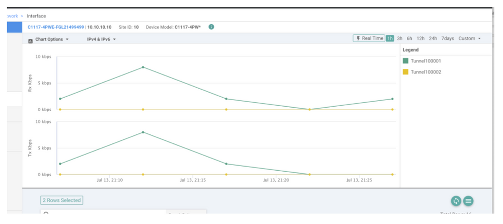
vManageでは、SIG IPSecトンネルのステータスをモニタできます。移動先 Monitor > Network, 目的のWANエッジデバイスを選択します。
ポリシーの横の [レポート(Report)] Interfaces タブをクリックします。デバイス内のすべてのインターフェイスのリストが表示されます。これには、ipsec1およびipsec2インターフェイスが含まれます。
次の図は、ipsec1トンネルがすべてのトラフィックを転送し、ipsec2がトラフィックを渡さないことを示しています。
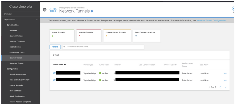
シスコでトンネルを確認することもできます Umbrella ポータルが図に示されています。
show sdwan secure-internet-gateway tunnels コマンドをCLIで発行して、トンネル情報を表示します。
C1117-4PWE-FGL21499499#show sdwan secure-internet-gateway tunnels
                                                                                  API   LAST
TUNNEL IF                                                                         HTTP  SUCCESSFUL     TUNNEL
NAME          TUNNEL ID  TUNNEL NAME                         FSM STATE            CODE  REQ            STATE
---------------------------------------------------------------------------------------------------------------
Tunnel100001  540798313  SITE10SYS10x10x10x10IFTunnel100001  st-tun-create-notif  200   create-tunnel  -
Tunnel100002  540798314  SITE10SYS10x10x10x10IFTunnel100002  st-tun-create-notif  200   create-tunnel  -
show endpoint-tracker と show ip sla summary コマンドを使用して、自動生成されたトラッカーとSLAに関する情報を表示します。
cEdge_Site1_East_01#show endpoint-tracker
Interface              Record Name            Status          RTT in msecs    Probe ID        Next Hop
Tunnel100001           #SIGL7#AUTO#TRACKER    Up              8               14              None
Tunnel100002           #SIGL7#AUTO#TRACKER    Up              2               12              None

cEdge_Site1_East_01#show ip sla summary
IPSLAs Latest Operation Summary
Codes: * active, ^ inactive, ~ pending
All Stats are in milliseconds. Stats with u are in microseconds

ID           Type        Destination       Stats       Return      Last
                                                       Code        Run
-----------------------------------------------------------------------
*12          http        10.10.10.10       RTT=6       OK          8 seconds ago


*14          http        10.10.10.10       RTT=17      OK          3 seconds ago
アクティブ/アクティブシナリオの確認
vManageでは、SIG IPSecトンネルのステータスをモニタできます。移動先 Monitor > Network, 目的のWANエッジデバイスを選択します。
ポリシーの横の [レポート(Report)] Interfaces タブをクリックすると、デバイス内のすべてのインターフェイスのリストが表示されます。これには、ipsec1およびipsec2インターフェイスが含まれます。
次の図は、ipsec1とipsec2の両方のトンネルがトラフィックを転送することを示しています。

show sdwan secure-internet-gateway tunnels コマンドをCLIで発行して、トンネル情報を表示します。
C1117-4PWE-FGL21499499#show sdwan secure-internet-gateway tunnels
                                                                                 API   LAST
TUNNEL IF                                                                         HTTP  SUCCESSFUL     TUNNEL
NAME          TUNNEL ID  TUNNEL NAME                         FSM STATE            CODE  REQ            STATE
---------------------------------------------------------------------------------------------------------------
Tunnel100001  540798313  SITE10SYS10x10x10x10IFTunnel100001  st-tun-create-notif  200   create-tunnel  -
Tunnel100002  540798314  SITE10SYS10x10x10x10IFTunnel100002  st-tun-create-notif  200   create-tunnel  -
show endpoint-tracker と show ip sla summary コマンドを使用して、自動生成されたトラッカーとSLAに関する情報を表示します。
cEdge_Site1_East_01#show endpoint-tracker
Interface              Record Name            Status          RTT in msecs    Probe ID        Next Hop
Tunnel100001           #SIGL7#AUTO#TRACKER    Up              8               14              None
Tunnel100002           #SIGL7#AUTO#TRACKER    Up              2               12              None

cEdge_Site1_East_01#show ip sla summary
IPSLAs Latest Operation Summary
Codes: * active, ^ inactive, ~ pending
All Stats are in milliseconds. Stats with u are in microseconds

ID           Type        Destination       Stats       Return      Last
                                                       Code        Run
-----------------------------------------------------------------------
*12          http        10.10.10.10       RTT=6       OK          8 seconds ago


*14          http        10.10.10.10       RTT=17      OK          3 seconds ago
関連情報
更新履歴
| 改定 | 発行日 | コメント |
|---|---|---|
6.0 |
22-Nov-2023 |
再認定 |
4.0 |
30-Dec-2021 |
小規模な変更 |
3.0 |
23-Dec-2021 |
追加情報の追加 |
2.0 |
16-Nov-2021 |
初版リリース |
1.0 |
16-Nov-2021 |
初版 |
シスコ エンジニア提供
- ダイアナ・ローラ・セラーノCisco TACエンジニア
- 編集:Amanda Nava ZarateCisco TACエンジニア
シスコに問い合わせ
- サポート ケースをオープン

- (シスコ サービス契約が必要です。)
 フィードバック