ASR1KのVRF対応L2TPv3でのXconnect
偏向のない言語
この製品のドキュメントセットは、偏向のない言語を使用するように配慮されています。このドキュメントセットでの偏向のない言語とは、年齢、障害、性別、人種的アイデンティティ、民族的アイデンティティ、性的指向、社会経済的地位、およびインターセクショナリティに基づく差別を意味しない言語として定義されています。製品ソフトウェアのユーザインターフェイスにハードコードされている言語、RFP のドキュメントに基づいて使用されている言語、または参照されているサードパーティ製品で使用されている言語によりドキュメントに例外が存在する場合があります。シスコのインクルーシブ ランゲージの取り組みの詳細は、こちらをご覧ください。
翻訳について
シスコは世界中のユーザにそれぞれの言語でサポート コンテンツを提供するために、機械と人による翻訳を組み合わせて、本ドキュメントを翻訳しています。ただし、最高度の機械翻訳であっても、専門家による翻訳のような正確性は確保されません。シスコは、これら翻訳の正確性について法的責任を負いません。原典である英語版(リンクからアクセス可能)もあわせて参照することを推奨します。
内容
概要
このドキュメントでは、IPおよびマルチプロトコルラベルスイッチング(MPLS)ネットワーク上でLayer 2 Tunneling Protocol(L2TP)v3 Xconnectを設定する際にVirtual Routing and Forwarding(VRF)を使用する方法について説明します。
背景説明
L2TPは、インターネット上のダイヤルアクセススペースでバーチャルプライベートネットワーク(VPN)を提供するために、インターネットサービスプロバイダー(ISP)によって使用されるトンネリングプロトコルです。
シスコのレイヤ2フォワーディング(L2F)プロトコルとMicrosoftのPoint-to-Point Tunneling Protocol(PPTP)を組み合わせたものです。 L2TPの主なコンポーネントは、L2TP Access Controller(LAC)とL2TP Network Server(LNS)です。
L2TPアクセスコントローラ:LACは、公衆電話交換網(PSTN)に接続されたアクセスサーバです。LACは、着信コールの発信側および発信コールの受信側です。LANまたはWAN経由でLNSに接続されます。
L2TPネットワークサーバ:LNSは、PPPセッションが終了し、認証されるL2TPプロトコルのネットワークサーバです。LNSは、発信コールの発信側と着信コールの受信側です。
L2TPv2は、IPネットワーク上でPPPトラフィックを伝送するように設計されています。ネットワークアクセス機器(DSL、ケーブルモデム、またはダイヤルアップアクセスインターフェイス)は、加入者からのPPP接続を受け入れ、L2TP経由でISPにPPPセッションをトンネリングしました。新しいバージョンL2TPv3は、バージョン2でサポートされた唯一のペイロードであるPPPに加えて、レイヤ2ペイロードを伝送するように設計されています。具体的には、レイヤ2VPNを使用してレイヤ2ペイロードをトンネリングするL2TPプロトコルをを定義します。この機能の利点は次のとおりです。
- L2TPv3はVPNの導入を簡素化
- L2TPv3にはMPLSは不要
- L2TPv3は、任意のペイロードに対してLayer 2 Tunneling over IPをサポートします
L2TPv3疑似回線の設定例を次に示します。
を選択します。![]() interface type slot/port
interface type slot/port
4.![]() xconnectpeer-ip-address vcidencapsulation l2tpv3 pw-classpw-class-name
xconnectpeer-ip-address vcidencapsulation l2tpv3 pw-classpw-class-name
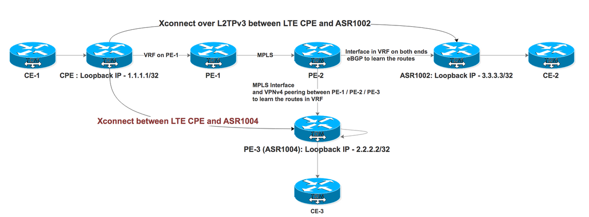
次に、VRFを使用する場合のL2TPv3 Xconnectの動作を示します。VRF1000のエンドポイントとCPEとASR1002(IP)およびASR1004(MPLS)の0間(VRF対応L2TPv3はASR1000プラットフォームではサポートされていません)。

テストケースI:VRFのエンドポイントを使用したL2TPv3 Xconnect over IPネットワーク

PE-1とPE-2は、ISPのMPLSネットワークを作成します。CPEはVRF経由でPE-1に接続され、ASR1002はVRF経由でPE-2に接続されます。ASR1002には、PE-2に接続されたインターフェイス上にVRFもあります。ASR1002からのCPEループバックの到達可能性は、VRF over IPインターフェイスを介して行われます。
ASR1002へのXconnect用CPEの設定:
interface FastEthernet4.2381

encapsulation dot1Q 2381

xconnect 3.3.3.3 2381 encapsulation l2tpv3 pw-class PSEUDO_CLASS >>>>>>>>>>> Xconnect with ASR1002


pseudowire-class PSEUDO_CLASS

encapsulation l2tpv3

interworking vlan

protocol l2tpv3 L2TP_CLASS

ip local interface Loopback0

ip tos reflect


l2tp-class L2TP_CLASS

authentication

password cisco


interface Gigabit0/1

ip address 192.168.8.190 255.255.255.0

end


Interface Loopback0

ip address 1.1.1.1 255.255.255.255

end


ip route 0.0.0.0 0.0.0.0 192.168.8.1 >>>>>>>>>>>>>> Default route towards PE-1
ASR1002の動作設定:
interface GigabitEthernet0/0/0.906 —————————————————> Interface connected to PE-2 is in VRF

encapsulation dot1Q 906

ip vrf forwarding L2TP_VRF

ip address 10.1.1.1 255.255.255.252


interface GigabitEthernet0/0/1.2381

encapsulation dot1Q 2381

xconnect 1.1.1.1 2381 encapsulation l2tpv3 pw-class PSEUDO_CLASS


pseudowire-class PSEUDO_CLASS

encapsulation l2tpv3

interworking vlan

protocol l2tpv3 L2TP_CLASS

ip local interface Loopback11


l2tp-class L2TP_CLASS

authentication

password cisco


interface Loopback11

ip vrf forwarding L2TP_VRF ————————————————————————————> Source is in VRF

ip address 3.3.3.3 255.255.255.255


router bgp 1


address-family ipv4 vrf L2TP_VRF

redistribute connected

neighbor 10.1.1.2 remote-as 2 ———————————————> eBGP with PE-2 in VRF

neighbor 10.1.1.2 activate

neighbor 10.1.1.2 soft-reconfiguration inbound

exit-address-family
VRF L2TP_VRF:
B 1.1.1.1/32 [20/0] via 10.1.1.2, 1d ——————————> Xconnect end point learned via eBGP in VRF
次に、CPEのXconnectのステータスを確認します。
CPE #sh xconnect all de

Legend:    XC ST=Xconnect State  S1=Segment1 State  S2=Segment2 State

  UP=Up       DN=Down            AD=Admin Down      IA=Inactive

  SB=Standby  HS=Hot Standby     RV=Recovering      NH=No Hardware


XC ST  Segment 1                         S1 Segment 2                         S2

------+---------------------------------+--+---------------------------------+--


UP pri   ac Fa4.2381:2381(Eth VLAN)      UP l2tp 3.3.3.3:2381              DOWN

            Interworking: vlan                   Session ID: 1906980494

                                                 Tunnel ID: 2886222725

                                                Protocol State: DOWN

                                                Remote Circuit State: DOWN

                                                pw-class: PSEUDO_CLASS_VLAN
セグメント2がダウンしているため、CPEからASR1002へのパスに問題があることが示されています。ただし、エンドポイントにpingを実行できます。CPEのデバッグは、エンドポイントへのトンネルが失敗したか、エンドポイントへのルートがないことを示します。
*Feb 15 08:12:47.225: L2TP _____:18136:8DF92CB9/uid:0[1.1.1.1/2381]: I CDN, flg TLS, ver 3, len 80

*Feb 15 08:12:47.225: L2TP _____:18136:8DF92CB9/uid:0[1.1.1.1/2381]:IETF v2:

*Feb 15 08:12:47.225: L2TP _____:18136:8DF92CB9/uid:0[1.1.1.1/2381]:Result Code

*Feb 15 08:12:47.225: L2TP _____:18136:8DF92CB9/uid:0[1.1.1.1/2381]:   Call disconnected for administrative reasons(3)

*Feb 15 08:12:47.225: L2TP _____:18136:8DF92CB9/uid:0[1.1.1.1/2381]:   Error code

*Feb 15 08:12:47.225: L2TP _____:18136:8DF92CB9/uid:0[1.1.1.1/2381]:     No error(0)

*Feb 15 08:12:47.225: L2TP _____:18136:8DF92CB9/uid:0[1.1.1.1/2381]:   Optional msg

*Feb 15 08:12:47.225: L2TP _____:18136:8DF92CB9/uid:0[1.1.1.1/2381]:       "Tunnel failed to 3.3.3.3" >>>>>>>>>>>>>>>>>

*Feb 15 08:12:47.225: L2TP _____:18136:8DF92CB9/uid:0[1.1.1.1/2381]:Cisco v3:
ここでの主な問題は、エンドポイントがASR1002上のVRF経由で到達可能であるということです。Xconnectエンドポイントを起動するには、グローバルルーティングテーブルに存在する必要があります。次に、VRF内のインターフェイスGigabitEthernet0/0/0.906を指すCPE Loopback 1.1.1.1/32のルートをグローバルに設定します。
 ip route 1.1.1.1 255.255.255.255 GigabitEthernet0/0/0.906 10.1.1.2


              S        1.1.1.1/32 [1/0] via 10.1.1.2, GigabitEthernet0/0/0.906
ダミースタティックルートが設定されると、Xconnectが起動します。Null0をポイントすることもできます。これは、VRFではなくグローバル経由でエンドポイントに到達でき、コントロールプレーンだけに使用されているとルータに認識させる回避策です。実際のデータプレーントラフィックはVRF経由のみです。
次に、VRFの有無を問わないpingの結果を示します。
ASR1002 #ping 1.1.1.1

Type escape sequence to abort.

Sending 5, 100-byte ICMP Echos to 1.1.1.1, timeout is 2 seconds:

.....

Success rate is 0 percent (0/5)


Ping vrf L2TP_VRF 1.1.1.1

Type escape sequence to abort.

Sending 5, 100-byte ICMP Echos to 1.1.1.1, timeout is 2 seconds:

!!!!!

Success rate is 100 percent (5/5), round-trip min/avg/max = 33/50/72 ms
CPEでのXconnectのステータス:
CPE #sh xconnect all de

Legend:    XC ST=Xconnect State  S1=Segment1 State  S2=Segment2 State

  UP=Up       DN=Down            AD=Admin Down      IA=Inactive

  SB=Standby  HS=Hot Standby     RV=Recovering      NH=No Hardware


XC ST  Segment 1                         S1 Segment 2                         S2

------+---------------------------------+--+---------------------------------+--


UP pri   ac Fa4.2381:2381(Eth VLAN)      UP l2tp3.3.3.3:2381             UP

            Interworking: vlan                   Session ID: 1906980494

                                                 Tunnel ID: 2886222725

                                                Protocol State: UP

                                                Remote Circuit State: UP

                                                pw-class: PSEUDO_CLASS_VLAN
テストケースII:VRFのエンドポイントを使用したMPLSネットワーク上のL2TPv3 Xconnect

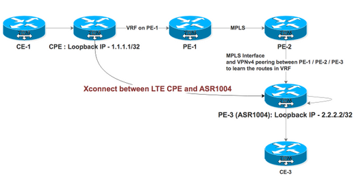
PE-1、PE-2、およびPE-3は、PE-2がルートリフレクタ(RR)として機能するISPのMPLSネットワークを作成します。CPEはVRF経由でPE-1に接続され、ASR1004はインターフェイスでMPLSが有効なPE-2に接続されます。ASR1004には、RR経由でPE-1からVPNv4ルートを受信するVRFもあります。ASR1004からのCPEループバックの到達可能性は、MPLSインターフェイス上のVRFを経由します。
ASR1004へのXconnect用CPEの設定:
interface FastEthernet4.2380

encapsulation dot1Q 2380

xconnect 2.2.2.2 2380 encapsulation l2tpv3 pw-class PSEUDO_CLASS  >>>>>>>>>>Xconnect with ASR1004


interface FastEthernet4.2381

encapsulation dot1Q 2381

xconnect 3.3.3.3 2381 encapsulation l2tpv3 pw-class PSEUDO_CLASS >>>>>>>>>>> Xconnect with ASR1002


pseudowire-class PSEUDO_CLASS

encapsulation l2tpv3

interworking vlan

protocol l2tpv3 L2TP_CLASS

ip local interface Loopback0

ip tos reflect


l2tp-class L2TP_CLASS

authentication

password cisco


interface Gigabit0/1

ip address 192.168.8.190 255.255.255.0

end


Interface Loopback0

ip address 1.1.1.1 255.255.255.255

end


ip route 0.0.0.0 0.0.0.0 192.168.8.1 >>>>>>>>>>>>>> Default route towards PE-1
ASR1004の設定:
interface GigabitEthernet0/0/1

no ip address

negotiation auto

service instance 2 ethernet

encapsulation dot1q 2380

xconnect 1.1.1.1 2380 encapsulation l2tpv3 pw-class PSEUDO_CLASS_VLAN

!

end


interface Loopback11

ip vrf forwarding L2TP_VRF —————————————————> Source Loopback in in VRF

ip address 2.2.2.2 255.255.255.255

end


pseudowire-class PSEUDO_CLASS_VLAN

encapsulation l2tpv3

interworking vlan

protocol l2tpv3 L2TP_CLASS

ip local interface Loopback11


l2tp-class L2TP_CLASS

authentication

password cisco


router bgp 2

address-family ipv4 vrf L2TP_VRF

redistribute connected

redistribute static

default-information originate

exit-address-family
Xconnectエンドポイントのルートエントリ:
ASR1004#sh ip rou vrf L2TP_VRF 1.1.1.1 .   ——————————————————> Xconnect End Point also learned via VRF

Routing Table: L2TP_VRF
Routing entry for 1.1.1.1/32
 Known via "bgp 2", distance 200, metric 0, type internal
 Last update from 11.11.11.11 6d17h ago
 Routing Descriptor Blocks:
 * 11.11.11.11 (default), from 22.22.22.22, 6d17h ago
 Route metric is 0, traffic share count is 1
 AS Hops 0
 MPLS label: 18
 MPLS Flags: MPLS Required


We observed that Segment 2 was continuously flapping on both ends.


ASR1004#sh xc all de

Legend:    XC ST=Xconnect State  S1=Segment1 State  S2=Segment2 State

  UP=Up       DN=Down            AD=Admin Down      IA=Inactive

  SB=Standby  HS=Hot Standby     RV=Recovering      NH=No Hardware


XC ST  Segment 1                         S1 Segment 2                         S2

------+---------------------------------+--+---------------------------------+--

DN pri   ac Gi0/0/1:2380(Eth VLAN)       UP l2tp 1.1.1.1:2380           DN  >>>>>>>>>>>>>>

            Interworking: vlan                   Session ID: 2543426569

                                                 Tunnel ID: 3352120314

                                                 Protocol State: DOWN

                                                 Remote Circuit State: DOWN

                                                 pw-class: PSEUDO_CLASS_VLAN

ASR1004#sh xc all de

Legend:    XC ST=Xconnect State  S1=Segment1 State  S2=Segment2 State

  UP=Up       DN=Down            AD=Admin Down      IA=Inactive

  SB=Standby  HS=Hot Standby     RV=Recovering      NH=No Hardware


XC ST  Segment 1                         S1 Segment 2                         S2

------+---------------------------------+--+---------------------------------+--

UP pri   ac Gi0/0/1:2380(Eth VLAN)       UP l2tp 1.1.1,1:2380           UP >>>>>>>>>>>>>>>>

            Interworking: vlan                   Session ID: 2543426569

                                                 Tunnel ID: 3352120314

                                                 Protocol State: UP

                                                 Remote Circuit State: UP

                                                 pw-class: PSEUDO_CLASS_VLAN
CPEからのログ:
CPE#sh xconnect all de

Legend:    XC ST=Xconnect State  S1=Segment1 State  S2=Segment2 State

  UP=Up       DN=Down            AD=Admin Down      IA=Inactive

  SB=Standby  HS=Hot Standby     RV=Recovering      NH=No Hardware


XC ST  Segment 1                         S1 Segment 2                         S2

------+---------------------------------+--+---------------------------------+--

DN pri   ac Fa4.2380:2380(Eth VLAN)      UP l2tp 2.2.2.2:2380            DN ---------------à Flapping with ASR1004

            Interworking: vlan                   Session ID: 3434660693

                                                 Tunnel ID: 1760690853

                                                 Protocol State: DOWN

                                                 Remote Circuit State: DOWN

                                                 pw-class: PSEUDO_CLASS

UP pri   ac Fa4.2381:2381(Eth VLAN)      UP l2tp 3.3.3.3:2381              UP ---------------------à Stable with ASR1002

            Interworking: vlan                   Session ID: 1906980494

                                                 Tunnel ID: 2886222725

                                                 Protocol State: UP

                                                 Remote Circuit State: UP

                                                 pw-class: PSEUDO_CLASS


CPE#sh l2tp session


L2TP Session Information Total tunnels 2 sessions 2


LocID      RemID      TunID      Username, Intf/      State  Last Chg Uniq ID

                                 Vcid, Circuit

2714490989 3697021268 1760690853 2380, Fa4.2380:2380  est   00:00:03 0  ————————> Flapping with ASR1004

1906980494 2361475239 2886222725 2381, Fa4.2381:2381  est   15:37:06 0       ————————> Stable with ASR1002
この場合、出口インターフェイスがMPLS対応インターフェイスであるため、スタティックルートを設定できません。回避策として、2つのインターフェイスが互いにループバックされ、VRF内の1つがグローバルに設定されています。
ASR1004#sh run int gi0/0/2

Building configuration...


Current configuration : 95 bytes

!

interface GigabitEthernet0/0/2 ——————————> Looped to Gi0/0/3

ip address 20.20.20.2 255.255.255.252

negotiation auto

end


#sh run int gi0/0/3

Building configuration...


Current configuration : 126 bytes

!

interface GigabitEthernet0/0/3

ip vrf forwarding L2TP_VRF

ip address 20.20.20.1 255.255.255.252

negotiation auto

end


ip route 10.246.131.62 255.255.255.255 20.20.20.1 ———————> Static route pointing towards an IP interface in Global


CPE#sh xconnect all de

Legend:    XC ST=Xconnect State  S1=Segment1 State  S2=Segment2 State

  UP=Up       DN=Down            AD=Admin Down      IA=Inactive

  SB=Standby  HS=Hot Standby     RV=Recovering      NH=No Hardware


XC ST  Segment 1                         S1 Segment 2                         S2

------+---------------------------------+--+---------------------------------+--

DN pri   ac Fa4.2380:2380(Eth VLAN)      UP l2tp 2.2.2.2:2380            UP

            Interworking: vlan                   Session ID: 3434660693

                                                 Tunnel ID: 1760690853

                                                 Protocol State: DOWN

                                                 Remote Circuit State: DOWN

                                                 pw-class: PSEUDO_CLASS

UP pri   ac Fa4.2381:2381(Eth VLAN)      UP l2tp 3.3.3.3:2381              UP

            Interworking: vlan                   Session ID: 1906980494

                                                 Tunnel ID: 2886222725

                                                 Protocol State: UP

                                                 Remote Circuit State: UP

                                                 pw-class: PSEUDO_CLASS


CPE#sh l2tp session
L2TPセッション情報合計トンネル2セッション2:
LocID      RemID      TunID      Username, Intf/      State  Last Chg Uniq ID

                                 Vcid, Circuit

2714490989 3697021268 1760690853 2380, Fa4.2380:2380  est   00:20:03 0

1906980494 2361475239 2886222725 2381, Fa4.2381:2381  est   15:37:06 0
トラフィックフローは、ASR1004の場合のように表示されます。
- トラフィックがASR1004のCPEから着信すると、MPLSインターフェイスGi0/0/1に着信し、Gi0/0/0アクセスポートに直接切り替えられます。
- アクセスポートGi0/0/0からトラフィックが着信すると、Gi0/0/0 -> Gi0/0/2 -> Gi0/0/3 -> Gi0/0/1のループパスが使用されます。
この回避策の主な問題は、パケット処理が2回行われるため、ASR1000プラットフォームでのQFP使用です。
ASR1004#  show platform packet-trace summary

Pkt   Input             Output            State  Reason

0     Gi0/0/3           Gi0/0/1           FWD

1     Gi0/0/3           Gi0/0/1           FWD

2     Gi0/0/3           Gi0/0/1           FWD

3     Gi0/0/0           Gi0/0/2           FWD

4     Gi0/0/0           Gi0/0/2           FWD

5     Gi0/0/0           Gi0/0/2           FWD

6     Gi0/0/0           Gi0/0/2           FWD

7     Gi0/0/0           Gi0/0/2           FWD
この動作は、Doc Bug:CSCvi42964
シスコ エンジニア提供
- Yogita BansalCisco TAC Engineer
シスコに問い合わせ
- サポート ケースをオープン

- (シスコ サービス契約が必要です。)
 フィードバック