Cisco IOS NAT - MPLS VPN との統合
内容
概要
Cisco IOS® ネットワーク アドレス変換(NAT)ソフトウェアを使用すると、複数の MPLS VPN 内にあるの複数のデバイスで IP アドレスがオーバーラップしている場合でも、それらの VPN から共有サービスにアクセスできます。Cisco IOS NAT は、VRF に対応しており、MPLS ネットワーク内のプロバイダー エッジ ルータで設定できます。
注:IOSのMPLSは、レガシーNATでのみサポートされます。現時点で、MPLS を搭載した NAT NVI 対応 Cisco IOS ではサポートされていません。
MPLS VPN の導入は、今後数年間で急速に増加すると予測されます。共有ネットワーク インフラストラクチャは、急速な拡大と柔軟な接続オプションに対応するため、インターネットワーク コミュニティに提供できるサービスをさらに拡充する推進力となることは間違いありません。
しかし、拡大を阻害する要因も存在します。IPv6 は予測可能な将来の接続ニーズに十分に対応する IP アドレス空間の提供を約束する技術ですが、その導入はいまだ初期段階に留まっています。既存のネットワークの多くは、RFC 1918 内で定義されているプライベート IP アドレッシング方式を使用しています。 ![]() 多くの場合、ネットワーク アドレス変換は、アドレス空間がオーバーラップしている場合や重複している部分がある場合に、ネットワークを相互接続するために使用されます。
多くの場合、ネットワーク アドレス変換は、アドレス空間がオーバーラップしている場合や重複している部分がある場合に、ネットワークを相互接続するために使用されます。
サービス プロバイダーや大規模企業は、ネットワーク アプリケーション サービスをお客様やパートナーに提供しようとする場合、またはお客様やパートナーとの間で共有しようとする場合に、サービスのユーザに対して生じる接続負担を最小限に抑える必要があります。そしてそれは、必要な限り多くの潜在的ユーザにネットワーク アプリケーション サービスを広く提供して、望ましい目標や収益を得るために求められこと、実現しなければならないことです。使用している IP アドレッシング方式が障害となって、潜在的ユーザから敬遠される事態は避ける必要があります。
一般的な MPLS VPNM インフラストラクチャ内に Cisco IOS NAT を導入することで、通信サービス プロバイダーは、お客様の接続負荷の一部を軽減できるとともに、より多くの共有アプリケーション サービスを、それらのサービスを利用するより多くのお客様に接続できるようになります。
NAT – MPLS 統合の利点
NAT と MPLS の統合は、サービス プロバイダーとその企業・官公庁のお客様の両方にメリットがあります。サービス プロバイダーは、共有サービスを導入し、それらのサービスへのアクセスを可能にするための方法をより多くの選択肢から選択できるようになります。サービスの多様化により、競合他社に対する競争力が向上します。
| サービス プロバイダーにとっての利点 | VPN にとっての利点 |
|---|---|
| サービスの多様化 | コストの削減 |
| 選択できるアクセス方法の多様化 | アクセスの簡素化 |
| 収益の向上 | アドレシングの柔軟性 |
現在のワークロードの一部をアウトソース化しようと検討している企業・官公庁のお客様も、サービス プロバイダーが多様なサービス品目を提供することのメリットを得られます。必要なアドレス変換実行の負荷をサービス プロバイダーのネットワークに転換すれば、お客様は複雑な管理作業から解放されます。お客様はそれまでどおりプライベート アドレスを使用しながら、共有サービスとインターネットへのアクセスを維持できます。サービス プロバイダーのネットワークに NAT 機能を統合すると、カスタマー エッジ ルータによる NAT 機能の実行が不要になり、企業・官公庁のお客様の総コストが低減する可能性もあります。
設計上の考慮事項
MPLS ネットワーク内で NAT を起動する設計を検討する場合は、まずアプリケーションの視点から必要なサービスを決定します。アプリケーションで使用するプロトコルや、アプリケーションに必要な特別なクライアント/サーバ通信を検討する必要があります。使用するプロトコルについて必要なサポートが提供されており、Cisco IOS NAT で対応していることを確認します。サポートされているプロトコルのリストについては、『Cisco IOS NAT アプリケーション レイヤ ゲートウェイ』を参照してください。
次に、共有サービスの予想される用途と予測されるトラフィック レート(単位:パケット/秒)を判断する必要があります。NAT は、ルータ CPU の処理能力を大量に消費する機能です。そのため、パフォーマンス要件は特定の導入オプションを選択し、対象とする NAT デバイスの数を判断する際の 1 つの要因となります。
また、セキュリティ上の問題と取るべき予防措置についても検討します。MPLS VPN は定義上プライベートであり、トラフィックが効率的に分割されますが、一般に共有サービス ネットワークは多くの VPN の間で共通です。
導入シナリオ
MPLS プロバイダー エッジ内での NAT 導入には、次の 2 つのオプションがあります。
-
出力 NAT PE を使用した集中型
-
入力 NAT PE を使用した分散型
MPLS ネットワーク内で、共有サービス ネットワークに最も近い位置にある出力ポイントに NAT 機能を設定する利点は次のとおりです。
-
設定作業の集中化によるサービス プロビジョニングの簡略化
-
トラブルシューティングの簡素化
-
運用の拡張性の向上
-
IP アドレス割り当ての要件の減少
ただし、これらの利点が得られる代わりに、拡張性やパフォーマンスは低下します。このことは、主要なトレードオフとして検討する必要があります。もちろん、MPLS ネットワークにこの機能を統合することが望ましくないと判断される場合、お客様のネットワーク内で NAT 機能を実行することも可能です。
入力 PE NAT
図1に示すように、MPLSネットワークの入力PEルータでNATを設定できます。この設計では、NAT機能を多くのエッジデバイスに分散してパフォーマンスを最適化しながら、拡張性を大幅に維持します。各 NAT PE は、その PE にローカルに接続されたサイトのトラフィックを処理します。どのパケットで変換が必要かは、NAT ルールに加え、アクセス コントロール リストまたはルート マップによって制御されます。
図 1:入力 PE NAT 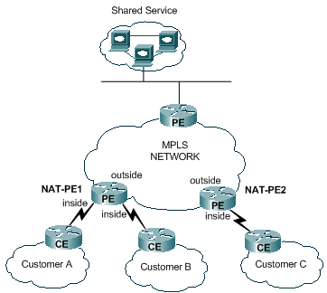
図2に示すように、2つのVRF間のNATを防止すると同時に、共有サービスにNATを提供する制限があります。これは、インターフェイスをNATの「内部」および「外部」インターフェイスとして指定する必要があるためです。1 つの PE 内にある 2 つの VRF 間での接続は、将来の Cisco IOS リリースでサポートされる予定です。
図 2:企業間 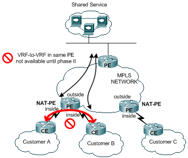
出力 PE NAT
図3に示すように、MPLSネットワークの出力PEルータでNATを設定できます。この設計では、中央PEが共有サービスにアクセスするすべての顧客ネットワークのルートを維持する必要があるため、拡張性が多少低下します。パケットの IP アドレスを変換するルータに対してトラフィックが過負荷にならないように、アプリケーション パフォーマンスの要件も考慮する必要があります。すべてのお客様の NAT がこのパスを使用して一元的に実行されるので、IP アドレス プールを共有できます。そのため、必要なサブネットの総数が少なくなります。
図 3:出力 PE NAT 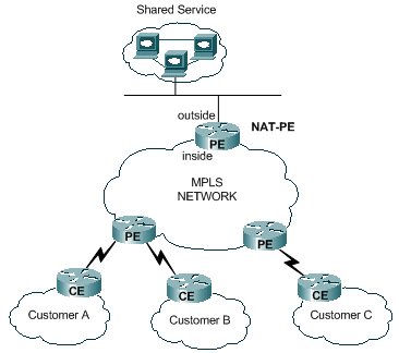
図4に示すように、出力PE NAT設計の拡張性を高めるために複数のルータを導入できます。このシナリオでは、カスタマーVPNを特定のNATルータで「プロビジョニング」できます。ネットワーク アドレス変換は、集約トラフィックと対象の VPN セットに提供される共有サービスとの間で実行されます。たとえば、顧客Aと顧客BのVPNからのトラフィックはNAT-PE1を使用し、顧客CのVPNとのトラフィックはNAT-PE2を使用します。各NAT PEは、定義された特定のVPNについてのみトラフィックをを伝送し、それらのサイトへのルートをを維持します。各 NAT PE ルータ内に別個の NAT アドレス プールを定義することで、パケットが共有サービス ネットワークから適切な NAT PE にルーティングされて変換された後、お客様の VPN に戻るようにすることができます。
図 4:複数の出力 PE NAT 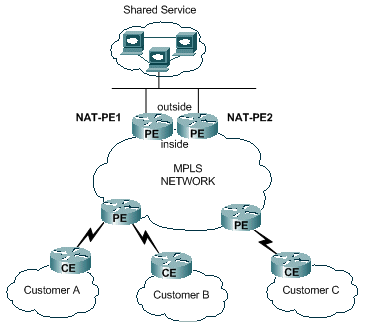
一元的設計では、共有サービス ネットワークの設定方法に大きな制約が課せられます。特に、共有サービス VPN とお客様の VPN の間で、MPLS VPN ルートのインポート/エクスポートを使用することはできません。これは、RFC 2547 で規定された MPLS 操作の性質に基づく制約です。 ![]() 拡張コミュニティとルート記述子を使用してルートをインポート/エクスポートした場合、NAT は、中央の NAT PE に送信されるパケットからソース VPN を判断できません。通常の場合、共有サービス ネットワークを VRF インターフェイスではなく汎用のインターフェイスとして設定します。次に、プロビジョニング プロセスの一環として、共有サービスへのアクセスが必要なお客様の VPN に関連付けられた各 VRF テーブルに対し、共有サービス ネットワークへのルートを中央の NAT PE に追加します。これについては、後ほど詳しく説明します。
拡張コミュニティとルート記述子を使用してルートをインポート/エクスポートした場合、NAT は、中央の NAT PE に送信されるパケットからソース VPN を判断できません。通常の場合、共有サービス ネットワークを VRF インターフェイスではなく汎用のインターフェイスとして設定します。次に、プロビジョニング プロセスの一環として、共有サービスへのアクセスが必要なお客様の VPN に関連付けられた各 VRF テーブルに対し、共有サービス ネットワークへのルートを中央の NAT PE に追加します。これについては、後ほど詳しく説明します。
導入オプションおよび設定の詳細
このセクションでは、導入オプションごとに詳細を説明します。図5に示すネットワークの例をすべて示します。このセクションの残りの部分については、この図を参照してください。
注:このドキュメントのVRF NATの動作を説明するために使用するネットワークには、PEルータのみが含まれています。コア「P」ルータは含まれていませんが、本質的なメカニズムは確認できます。
図 5:VRF NAT の設定例 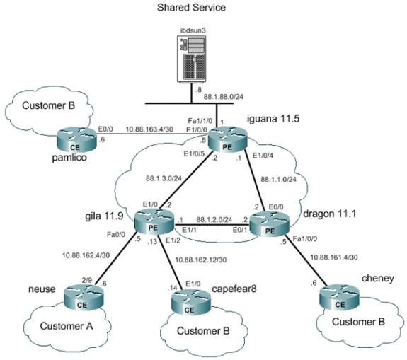
出力 PE NAT
この例では、gila と dragon の 2 つのプロバイダー エッジ ルータが、サンプル PE ルータとして設定されています。共有サービス LAN に近い中央の PE(iguana)が、NAT 用に設定されています。1 つの NAT プールが、共有サービスへのアクセスを必要とするお客様の各 VPN によって共有されています。NAT は、アドレスが 88.1.88.8 の共有サービス ホストに宛てたパケットに対してのみ実行されます。
出力 PE NAT のデータ転送
MPLS において、各パケットは入力 PE でネットワークに入り、出力 PE で MPLS ネットワークから出ます。入力側から出力側に通じるラベル スイッチング ルータのパスは、ラベル スイッチング パス(LSP)と呼ばれます。 LSP は双方向パスです。リターン トラフィックには、異なる LSP が使用されます。
出力 PE NAT の使用時に、共有サービスのユーザから送信されたすべてのトラフィックに対して、転送等価クラス(FEC)が有効に定義されます。つまり、共有サービス LAN に宛てられたすべてのパケットが共通 FEC のメンバとなります。パケットは、ネットワークの入力エッジで一度だけ特定の FEC に割り当てられ、LSP を通って出力 PE に移動します。FEC は特定のラベルを追加することで、データ パケット内で指定されます。
VPN から共有サービスへのパケット フロー
アドレス方式がオーバーラップしている複数の VPN 内のデバイスが共有サービス ホストにアクセスするには、NAT が必要です。出力 PE で NAT が設定されている場合は、重複したアドレスを区別し、正しいルーティングを保証するための VRF 識別子がネットワーク アドレス変換テーブルに追加されます。
図 6:出力 PE NAT に送信されるパケット 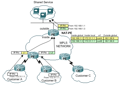
図 6 では、IP アドレッシング方式が重複している 2 つのお客様の VPN から、共有サービス ホスト宛てにパケットが送信される場合を示しています。図は、Customer Aで送信元アドレスが172.31.1.1、宛先が88.1.88.8の共有サーバであるパケットを示しています。同じ送信元IPアドレスを持つCustomer Bからの別のパケットも、同じ共有サーバに送信されます。これらのパケットが PE ルータに到達した時点で、転送情報ベース(FIB)で宛先 IP ネットワークのレイヤ 3 ルックアップが実行されます。
PE ルータは FIB エントリの指示に従い、ラベル スタックを使用してトラフィックを出力 PE に転送します。スタックのボトム ラベルは、宛先 PE ルータ(この例ではルータ iguana)によって割り当てられます。
iguana#
show ip cef vrf custA 88.1.88.8

88.1.88.8/32, version 47, epoch 0, cached adjacency 88.1.3.2
0 packets, 0 bytes
  tag information set
    local tag: VPN-route-head
    fast tag rewrite with Et1/0, 88.1.3.2, tags imposed: {24}
  via 88.1.11.5, 0 dependencies, recursive
    next hop 88.1.3.2, Ethernet1/0 via 88.1.11.5/32
    valid cached adjacency
    tag rewrite with Et1/0, 88.1.3.2, tags imposed: {24}
iguana# show ip cef vrf custB 88.1.88.8
88.1.88.8/32, version 77, epoch 0, cached adjacency 88.1.3.2
0 packets, 0 bytes
  tag information set
    local tag: VPN-route-head
    fast tag rewrite with Et1/0, 88.1.3.2, tags imposed: {28}
  via 88.1.11.5, 0 dependencies, recursive
    next hop 88.1.3.2, Ethernet1/0 via 88.1.11.5/32
    valid cached adjacency
    tag rewrite with Et1/0, 88.1.3.2, tags imposed: {28}
iguana#
上の画面表示を見ると、VRF custA から発信されたパケットにタグ値 24(0x18)が適用され、VRF custB から発信されたパケットにがタグ値 28(0x1C)が適用されていることがわかります。
この例では、ネットワーク内に「P」ルータが存在しないので、それ以外のタグは適用されません。しかしコア ルータが使用されていれば、ここで外部ラベルが適用され、パケットが出力 PE に到達するまで、コア ネットワーク内でラベル スワッピングの通常のプロセスが実行されます。
gila ルータが出力 PE に直接接続されているため、タグは追加される前にポップされることがわかります。
gila#
show tag-switching forwarding-table

Local  Outgoing    Prefix            Bytes tag  Outgoing   Next Hop
tag    tag or VC   or Tunnel Id      switched   interface
16     Pop tag     88.1.1.0/24       0          Et1/1      88.1.2.2
       Pop tag     88.1.1.0/24       0          Et1/0      88.1.3.2
17     Pop tag     88.1.4.0/24       0          Et1/1      88.1.2.2
18     Pop tag     88.1.10.0/24      0          Et1/1      88.1.2.2
19     Pop tag     88.1.11.1/32      0          Et1/1      88.1.2.2
20     Pop tag     88.1.5.0/24       0          Et1/0      88.1.3.2
21     19          88.1.11.10/32     0          Et1/1      88.1.2.2
       22          88.1.11.10/32     0          Et1/0      88.1.3.2
22     20          172.18.60.176/32  0          Et1/1      88.1.2.2
       23          172.18.60.176/32  0          Et1/0      88.1.3.2
23     Untagged    172.31.1.0/24[V]  4980       Fa0/0      10.88.162.6
24     Aggregate   10.88.162.4/30[V] 1920
25     Aggregate   10.88.162.8/30[V] 137104
26     Untagged    172.31.1.0/24[V]  570        Et1/2      10.88.162.14
27     Aggregate   10.88.162.12/30[V]   \
                                     273480
30     Pop tag     88.1.11.5/32      0          Et1/0      88.1.3.2
31     Pop tag     88.1.88.0/24      0          Et1/0      88.1.3.2
32     16          88.1.97.0/24      0          Et1/0      88.1.3.2
33     Pop tag     88.1.99.0/24      0          Et1/0      88.1.3.2
gila#
gila# show tag-switching forwarding-table  88.1.88.0 detail
Local  Outgoing    Prefix            Bytes tag  Outgoing   Next Hop
tag    tag or VC   or Tunnel Id      switched   interface
31     Pop tag     88.1.88.0/24      0          Et1/0      88.1.3.2
        MAC/Encaps=14/14, MRU=1504, Tag Stack{}
        005054D92A250090BF9C6C1C8847
        No output feature configured
    Per-packet load-sharing
gila#
次の画面表示は、出力 PE NAT ルータ(iguana のインターフェイス E1/0/5)で受信されたエコー パケットを示しています。
From CustA:
DLC:  ----- DLC Header -----
        DLC:
        DLC:  Frame 1 arrived at  16:21:34.8415; frame size is 118 (0076 hex)
            bytes.
        DLC:  Destination = Station 005054D92A25
        DLC:  Source      = Station 0090BF9C6C1C
        DLC:  Ethertype   = 8847 (MPLS)
        DLC:
  MPLS: ----- MPLS Label Stack  -----
        MPLS:
        MPLS: Label Value                   = 00018
        MPLS: Reserved For Experimental Use = 0
        MPLS: Stack Value                   = 1 (Bottom of Stack)
        MPLS: Time to Live                  = 254 (hops)
        MPLS:
  IP: ----- IP Header -----
        IP:
        IP: Version = 4, header length = 20 bytes
        IP: Type of service = 00
        IP:       000. ....   = routine
        IP:       ...0 .... = normal delay
        IP:       .... 0... = normal throughput
        IP:       .... .0.. = normal reliability
        IP:       .... ..0. = ECT bit - transport protocol will ignore the CE
            bit
        IP:       .... ...0 = CE bit - no congestion
        IP: Total length    = 100 bytes
        IP: Identification  = 175
        IP: Flags           = 0X
        IP:       .0.. .... = may fragment
        IP:       ..0. .... = last fragment
        IP: Fragment offset = 0 bytes
        IP: Time to live    = 254 seconds/hops
        IP: Protocol        = 1 (ICMP)
        IP: Header checksum = 5EC0 (correct)
        IP: Source address      = [172.31.1.1]
        IP: Destination address = [88.1.88.8]
        IP: No options
        IP:
  ICMP: ----- ICMP header -----
        ICMP:
        ICMP: Type = 8 (Echo)
        ICMP: Code = 0
        ICMP: Checksum = 4AF1 (correct)
        ICMP: Identifier = 4713
        ICMP: Sequence number = 6957
        ICMP: [72 bytes of data]
        ICMP:
        ICMP: [Normal end of "ICMP header".]
From CustB:
DLC:  ----- DLC Header -----
        DLC:
        DLC:  Frame 11 arrived at  16:21:37.1558; frame size is 118 (0076 hex)
            bytes.
        DLC:  Destination = Station 005054D92A25
        DLC:  Source      = Station 0090BF9C6C1C
        DLC:  Ethertype   = 8847 (MPLS)
        DLC:
  MPLS: ----- MPLS Label Stack  -----
        MPLS:
        MPLS: Label Value                   = 0001C
        MPLS: Reserved For Experimental Use = 0
        MPLS: Stack Value                   = 1 (Bottom of Stack)
        MPLS: Time to Live                  = 254 (hops)
        MPLS:
  IP: ----- IP Header -----
        IP:
        IP: Version = 4, header length = 20 bytes
        IP: Type of service = 00
        IP:       000. ....   = routine
        IP:       ...0 .... = normal delay
        IP:       .... 0... = normal throughput
        IP:       .... .0.. = normal reliability
        IP:       .... ..0. = ECT bit - transport protocol will ignore the CE
            bit
        IP:       .... ...0 = CE bit - no congestion
        IP: Total length    = 100 bytes
        IP: Identification  = 165
        IP: Flags           = 0X
        IP:       .0.. .... = may fragment
        IP:       ..0. .... = last fragment
        IP: Fragment offset = 0 bytes
        IP: Time to live    = 254 seconds/hops
        IP: Protocol        = 1 (ICMP)
        IP: Header checksum = 5ECA (correct)
        IP: Source address      = [172.31.1.1]
        IP: Destination address = [88.1.88.8]
        IP: No options
        IP:
  ICMP: ----- ICMP header -----
        ICMP:
        ICMP: Type = 8 (Echo)
        ICMP: Code = 0
        ICMP: Checksum = AD5E (correct)
        ICMP: Identifier = 3365
        ICMP: Sequence number = 7935
        ICMP: [72 bytes of data]
        ICMP:
        ICMP: [Normal end of "ICMP header".]
これらの ping により、出力 PE ルータ iguana にある NAT テーブルに次のエントリが作成されます。上に示すパケットに対して作成された特定のエントリの検索には、ICMP 識別子を使用できます。
iguana#
show ip nat translations

Pro Inside global      Inside local       Outside local      Outside global
icmp 192.168.1.3:3365  172.31.1.1:3365    88.1.88.8:3365     88.1.88.8:3365
icmp 192.168.1.3:3366  172.31.1.1:3366    88.1.88.8:3366     88.1.88.8:3366
icmp 192.168.1.3:3367  172.31.1.1:3367    88.1.88.8:3367     88.1.88.8:3367
icmp 192.168.1.3:3368  172.31.1.1:3368    88.1.88.8:3368     88.1.88.8:3368
icmp 192.168.1.3:3369  172.31.1.1:3369    88.1.88.8:3369     88.1.88.8:3369
icmp 192.168.1.1:4713  172.31.1.1:4713    88.1.88.8:4713     88.1.88.8:4713
icmp 192.168.1.1:4714  172.31.1.1:4714    88.1.88.8:4714     88.1.88.8:4714
icmp 192.168.1.1:4715  172.31.1.1:4715    88.1.88.8:4715     88.1.88.8:4715
icmp 192.168.1.1:4716  172.31.1.1:4716    88.1.88.8:4716     88.1.88.8:4716
icmp 192.168.1.1:4717  172.31.1.1:4717    88.1.88.8:4717     88.1.88.8:4717
iguana#
show ip nat translations verbose

Pro Inside global      Inside local       Outside local      Outside global
icmp 192.168.1.3:3365  172.31.1.1:3365    88.1.88.8:3365     88.1.88.8:3365
    create 00:00:34, use 00:00:34, left 00:00:25, Map-Id(In): 2,
    flags:
extended, use_count: 0, VRF : custB
icmp 192.168.1.3:3366  172.31.1.1:3366    88.1.88.8:3366     88.1.88.8:3366
    create 00:00:34, use 00:00:34, left 00:00:25, Map-Id(In): 2,
    flags:
extended, use_count: 0, VRF : custB
icmp 192.168.1.3:3367  172.31.1.1:3367    88.1.88.8:3367     88.1.88.8:3367
    create 00:00:34, use 00:00:34, left 00:00:25, Map-Id(In): 2,
    flags:
extended, use_count: 0, VRF : custB
icmp 192.168.1.3:3368  172.31.1.1:3368    88.1.88.8:3368     88.1.88.8:3368
    create 00:00:34, use 00:00:34, left 00:00:25, Map-Id(In): 2,
    flags:
extended, use_count: 0, VRF : custB
icmp 192.168.1.3:3369  172.31.1.1:3369    88.1.88.8:3369     88.1.88.8:3369
    create 00:00:34, use 00:00:34, left 00:00:25, Map-Id(In): 2,
    flags:
extended, use_count: 0, VRF : custB
icmp 192.168.1.1:4713  172.31.1.1:4713    88.1.88.8:4713     88.1.88.8:4713
    create 00:00:37, use 00:00:37, left 00:00:22, Map-Id(In): 1,
Pro Inside global      Inside local       Outside local      Outside global
    flags:
extended, use_count: 0, VRF : custA
icmp 192.168.1.1:4714  172.31.1.1:4714    88.1.88.8:4714     88.1.88.8:4714
    create 00:00:37, use 00:00:37, left 00:00:22, Map-Id(In): 1,
    flags:
extended, use_count: 0, VRF : custA
icmp 192.168.1.1:4715  172.31.1.1:4715    88.1.88.8:4715     88.1.88.8:4715
    create 00:00:37, use 00:00:37, left 00:00:22, Map-Id(In): 1,
    flags:
extended, use_count: 0, VRF : custA
icmp 192.168.1.1:4716  172.31.1.1:4716    88.1.88.8:4716     88.1.88.8:4716
    create 00:00:37, use 00:00:37, left 00:00:22, Map-Id(In): 1,
    flags:
extended, use_count: 0, VRF : custA
icmp 192.168.1.1:4717  172.31.1.1:4717    88.1.88.8:4717     88.1.88.8:4717
    create 00:00:37, use 00:00:37, left 00:00:22, Map-Id(In): 1,
    flags:
extended, use_count: 0, VRF : custA
iguana#
共有サービスから元の VPN への返送パケット フロー
共有サービス ホストにアクセスしたデバイスにパケットが返送されるときは、ルーティングに先立って NAT テーブルが検索されます(パケットは、NATの「outside」インターフェイスから「inside」インターフェイスに送信されます)。 一意の各エントリに対応する VRF 識別子が含まれているので、パケットが適切に変換してルーティングされます。
図 7:共有サービスのユーザへのパケットの返送 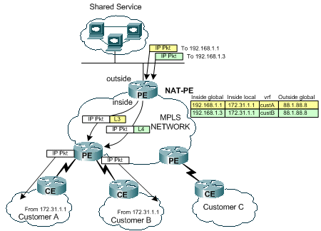
図 7 に示すように、リターン トラフィックはまず NAT によって調べられ、一致する変換エントリが検索されます。たとえば、パケットは宛先192.168.1.1に送信されます。NATテーブルが検索されます。一致するエントリが検出されると、「inside local」アドレス(172.31.1.1)への適切な変換が行われた後で、NAT エントリにある関連付けられた VRF ID を使用して、隣接ルックアップが実行されます。
iguana# show ip cef vrf custA 172.31.1.0
172.31.1.0/24, version 12, epoch 0, cached adjacency 88.1.3.1
0 packets, 0 bytes
  tag information set
    local tag: VPN-route-head
    fast tag rewrite with Et1/0/5, 88.1.3.1, tags imposed: {23}
  via 88.1.11.9, 0 dependencies, recursive
    next hop 88.1.3.1, Ethernet1/0/5 via 88.1.11.9/32
    valid cached adjacency
    tag rewrite with Et1/0/5, 88.1.3.1, tags imposed: {23}
iguana# show ip cef vrf custB 172.31.1.0
172.31.1.0/24, version 18, epoch 0, cached adjacency 88.1.3.1
0 packets, 0 bytes
  tag information set
    local tag: VPN-route-head
    fast tag rewrite with Et1/0/5, 88.1.3.1, tags imposed: {26}
  via 88.1.11.9, 0 dependencies, recursive
    next hop 88.1.3.1, Ethernet1/0/5 via 88.1.11.9/32
    valid cached adjacency
    tag rewrite with Et1/0/5, 88.1.3.1, tags imposed: {26}
iguana#
VRF custA の 172.31.1.0/24 宛てのトラフィックにはラベル 23(0x17)が使用され、VRF custB の 172.31.1.0/24 宛てパケットにはラベル 26(0x1A)が使用されています。
ルータ iguana から送信されたエコー応答パケットの情報は、次のように画面表示されます。
To custA:
  DLC:  ----- DLC Header -----
        DLC:
        DLC:  Frame 2 arrived at  16:21:34.8436; frame size is 118 (0076 hex)
            bytes.
        DLC:  Destination = Station 0090BF9C6C1C
        DLC:  Source      = Station 005054D92A25
        DLC:  Ethertype   = 8847 (MPLS)
        DLC:
  MPLS: ----- MPLS Label Stack  -----
        MPLS:
        MPLS: Label Value                   = 00017
        MPLS: Reserved For Experimental Use = 0
        MPLS: Stack Value                   = 1 (Bottom of Stack)
        MPLS: Time to Live                  = 254 (hops)
        MPLS:
  IP: ----- IP Header -----
        IP:
        IP: Version = 4, header length = 20 bytes
        IP: Type of service = 00
        IP:       000. ....   = routine
        IP:       ...0 .... = normal delay
        IP:       .... 0... = normal throughput
        IP:       .... .0.. = normal reliability
        IP:       .... ..0. = ECT bit - transport protocol will ignore the CE
            bit
        IP:       .... ...0 = CE bit - no congestion
        IP: Total length    = 100 bytes
        IP: Identification  = 56893
        IP: Flags           = 4X
        IP:       .1.. .... = don't fragment
        IP:       ..0. .... = last fragment
        IP: Fragment offset = 0 bytes
        IP: Time to live    = 254 seconds/hops
        IP: Protocol        = 1 (ICMP)
        IP: Header checksum = 4131 (correct)
        IP: Source address      = [88.1.88.8]
        IP: Destination address = [172.31.1.1]
        IP: No options
        IP:
  ICMP: ----- ICMP header -----
        ICMP:
        ICMP: Type = 0 (Echo reply)
        ICMP: Code = 0
        ICMP: Checksum = 52F1 (correct)
        ICMP: Identifier = 4713
        ICMP: Sequence number = 6957
        ICMP: [72 bytes of data]
        ICMP:
        ICMP: [Normal end of "ICMP header".]
このパケットが宛先 PE ルータに到達すると、パケットを送信するための適切な VRF とインターフェイスが、ラベルを使用して判定されます。
gila#
show mpls forwarding-table

Local  Outgoing    Prefix            Bytes tag  Outgoing   Next Hop
tag    tag or VC   or Tunnel Id      switched   interface
16     Pop tag     88.1.1.0/24       0          Et1/1      88.1.2.2
       Pop tag     88.1.1.0/24       0          Et1/0      88.1.3.2
17     Pop tag     88.1.4.0/24       0          Et1/1      88.1.2.2
18     Pop tag     88.1.10.0/24      0          Et1/1      88.1.2.2
19     Pop tag     88.1.11.1/32      0          Et1/1      88.1.2.2
20     Pop tag     88.1.5.0/24       0          Et1/0      88.1.3.2
21     19          88.1.11.10/32     0          Et1/1      88.1.2.2
       22          88.1.11.10/32     0          Et1/0      88.1.3.2
22     20          172.18.60.176/32  0          Et1/1      88.1.2.2
       23          172.18.60.176/32  0          Et1/0      88.1.3.2
23     Untagged    172.31.1.0/24[V]  6306       Fa0/0      10.88.162.6
24     Aggregate   10.88.162.4/30[V] 1920
25     Aggregate   10.88.162.8/30[V] 487120
26     Untagged    172.31.1.0/24[V]  1896       Et1/2      10.88.162.14
27     Aggregate   10.88.162.12/30[V]   \
                                     972200
30     Pop tag     88.1.11.5/32      0          Et1/0      88.1.3.2
31     Pop tag     88.1.88.0/24      0          Et1/0      88.1.3.2
32     16          88.1.97.0/24      0          Et1/0      88.1.3.2
33     Pop tag     88.1.99.0/24      0          Et1/0      88.1.3.2
gila#
設定
ここに示すコンフィギュレーションでは、簡略化のために不必要な情報は省略されています。
IGUANA:
!
ip vrf custA
 rd 65002:100
 route-target export 65002:100
 route-target import 65002:100
!
ip vrf custB
 rd 65002:200
 route-target export 65002:200
 route-target import 65002:200
!
ip cef
mpls label protocol ldp
tag-switching tdp router-id Loopback0
!
interface Loopback0
 ip address 88.1.11.5 255.255.255.255
 no ip route-cache
 no ip mroute-cache
!
interface Loopback11
 ip vrf forwarding custA
 ip address 172.16.1.1 255.255.255.255
!
interface Ethernet1/0/0
 ip vrf forwarding custB
 ip address 10.88.163.5 255.255.255.252
 no ip route-cache
 no ip mroute-cache
!
interface Ethernet1/0/4
 ip address 88.1.1.1 255.255.255.0
 ip nat inside
 no ip mroute-cache
 tag-switching ip
!
interface Ethernet1/0/5
 ip address 88.1.3.2 255.255.255.0
 ip nat inside
 no ip mroute-cache
 tag-switching ip
!
!
interface FastEthernet1/1/0
 ip address 88.1.88.1 255.255.255.0
 ip nat outside
 full-duplex
!
interface FastEthernet5/0/0
 ip address 88.1.99.1 255.255.255.0
 speed 100
 full-duplex
!
router ospf 881
 log-adjacency-changes
 redistribute static subnets
 network 88.1.0.0 0.0.255.255 area 0
!
router bgp 65002
 no synchronization
 no bgp default ipv4-unicast
 bgp log-neighbor-changes
 neighbor 88.1.11.1 remote-as 65002
 neighbor 88.1.11.1 update-source Loopback0
 neighbor 88.1.11.9 remote-as 65002
 neighbor 88.1.11.9 update-source Loopback0
 neighbor 88.1.11.10 remote-as 65002
 neighbor 88.1.11.10 update-source Loopback0
 no auto-summary
 !
 address-family ipv4 multicast
 no auto-summary
 no synchronization
 exit-address-family
 !
 address-family vpnv4
 neighbor 88.1.11.1 activate
 neighbor 88.1.11.1 send-community extended
 neighbor 88.1.11.9 activate
 neighbor 88.1.11.9 send-community extended
 no auto-summary
 exit-address-family
 !
 address-family ipv4
 neighbor 88.1.11.1 activate
 neighbor 88.1.11.9 activate
 neighbor 88.1.11.10 activate
 no auto-summary
 no synchronization
 exit-address-family
 !
 address-family ipv4 vrf custB
 redistribute connected
 redistribute static
 no auto-summary
 no synchronization
 exit-address-family
 !
 address-family ipv4 vrf custA
 redistribute static
 no auto-summary
 no synchronization
 exit-address-family
!
ip nat pool SSPOOL1 192.168.1.1 192.168.1.254 prefix-length 24
ip nat inside source list 181 pool SSPOOL1 vrf custA overload
ip nat inside source list 181 pool SSPOOL1 vrf custB overload
ip classless
ip route 88.1.88.0 255.255.255.0 FastEthernet1/1/0
ip route 88.1.97.0 255.255.255.0 FastEthernet5/0/0 88.1.99.2
ip route 88.1.99.0 255.255.255.0 FastEthernet5/0/0 88.1.99.2
ip route 192.168.1.0 255.255.255.0 Null0
ip route vrf custA 88.1.88.8 255.255.255.255 FastEthernet1/1/0 88.1.88.8 global
ip route vrf custB 10.88.208.0 255.255.240.0 10.88.163.6
ip route vrf custB 64.102.0.0 255.255.0.0 10.88.163.6
ip route vrf custB 88.1.88.8 255.255.255.255 FastEthernet1/1/0 88.1.88.8 global
ip route vrf custB 128.0.0.0 255.0.0.0 10.88.163.6
no ip http server
!
access-list 181 permit ip any host 88.1.88.8
!
GILA:

!
ip vrf custA
 rd 65002:100
 route-target export 65002:100
 route-target import 65002:100
!
ip vrf custB
 rd 65002:200
 route-target export 65002:200
 route-target import 65002:200
!
ip cef
mpls label protocol ldp
tag-switching tdp router-id Loopback0
!
interface Loopback0
 ip address 88.1.11.9 255.255.255.255
!
interface FastEthernet0/0
 ip vrf forwarding custA
 ip address 10.88.162.5 255.255.255.252
 duplex full
!
interface Ethernet1/0
 ip address 88.1.3.1 255.255.255.0
 no ip mroute-cache
 duplex half
 tag-switching ip
!
interface Ethernet1/1
 ip address 88.1.2.1 255.255.255.0
 no ip mroute-cache
 duplex half
 tag-switching ip
!
interface Ethernet1/2
 ip vrf forwarding custB
 ip address 10.88.162.13 255.255.255.252
 ip ospf cost 100
 duplex half
!
interface FastEthernet2/0
 ip vrf forwarding custA
 ip address 10.88.162.9 255.255.255.252
 duplex full
!
router ospf 881
 log-adjacency-changes
 redistribute static subnets
 network 88.1.0.0 0.0.255.255 area 0
 default-metric 30
!
router bgp 65002
 no synchronization
 no bgp default ipv4-unicast
 bgp log-neighbor-changes
 neighbor 88.1.11.1 remote-as 65002
 neighbor 88.1.11.1 update-source Loopback0
 neighbor 88.1.11.1 activate
 neighbor 88.1.11.5 remote-as 65002
 neighbor 88.1.11.5 update-source Loopback0
 neighbor 88.1.11.5 activate
 no auto-summary
 !
 address-family ipv4 vrf custB
 redistribute connected
 redistribute static
 no auto-summary
 no synchronization
 exit-address-family
 !
 address-family ipv4 vrf custA
 redistribute connected
 redistribute static
 no auto-summary
 no synchronization
 exit-address-family
 !
 address-family vpnv4
 neighbor 88.1.11.1 activate
 neighbor 88.1.11.1 send-community extended
 neighbor 88.1.11.5 activate
 neighbor 88.1.11.5 send-community extended
 no auto-summary
 exit-address-family
!
ip classless
ip route vrf custA 172.31.1.0 255.255.255.0 FastEthernet0/0 10.88.162.6
ip route vrf custB 172.31.1.0 255.255.255.0 Ethernet1/2 10.88.162.14
!
ルータ dragon の設定は、gila の設定とほぼ同じです。
ルート ターゲットのインポート/エクスポートは不可
共有サービス ネットワークを VRF インスタンス自体として設定する場合、中央の NAT を出力 PE に置くことはできません。出力 PE NAT では異なる着信パケットの違いが区別できず、送信元のサブネットヘは 1 つのルートしか存在しないためです。
注:次の表示は、無効な設定の結果を示すことを目的としています。
サンプル ネットワークの設定では、共有サービス ネットワークが VRF インスタンス(VRF 名:sserver)として定義されています。 そこで、入力 PE の CEF テーブルは、次のように画面表示されます。
gila# show ip cef vrf custA 88.1.88.0
88.1.88.0/24, version 45, epoch 0, cached adjacency 88.1.3.2
0 packets, 0 bytes
  tag information set
    local tag: VPN-route-head
    fast tag rewrite with Et1/0, 88.1.3.2, tags imposed: {24}
  via 88.1.11.5, 0 dependencies, recursive
    next hop 88.1.3.2, Ethernet1/0 via 88.1.11.5/32
    valid cached adjacency
    tag rewrite with Et1/0, 88.1.3.2, tags imposed: {24}
gila#
gila# show ip cef vrf custB 88.1.88.0
88.1.88.0/24, version 71, epoch 0, cached adjacency 88.1.3.2
0 packets, 0 bytes
  tag information set
    local tag: VPN-route-head
    fast tag rewrite with Et1/0, 88.1.3.2, tags imposed: {24}
  via 88.1.11.5, 0 dependencies, recursive
    next hop 88.1.3.2, Ethernet1/0 via 88.1.11.5/32
    valid cached adjacency
    tag rewrite with Et1/0, 88.1.3.2, tags imposed: {24}
gila#
iguana#
show tag-switching forwarding vrftags 24
Local  Outgoing    Prefix            Bytes tag  Outgoing   Next Hop
tag    tag or VC   or Tunnel Id      switched   interface
24     Aggregate   88.1.88.0/24[V]   10988
iguana#
注:タグ値24がVRF custAとVRF custBの両方に対して課されていることに注意してください。
以下の画面表示は、共有サービスである VRF インスタンス「sserver」のルーティング テーブルを示します。
iguana#
show ip route vrf sserver 172.31.1.1
Routing entry for 172.31.1.0/24
  Known via "bgp 65002", distance 200, metric 0, type internal
  Last update from 88.1.11.9 1d01h ago
  Routing Descriptor Blocks:
  * 88.1.11.9 (Default-IP-Routing-Table), from 88.1.11.9, 1d01h ago
      Route metric is 0, traffic share count is 1
      AS Hops 0
注:出力PEルータ(iguana)の観点から見ると、宛先ネットワークに対して1つのルートしか存在しません。
そのため、複数のお客様の VPN からのトラフィックを区別できず、リターン トラフィックを適切な VPN に返送することができません。共有サービスを VRF インスタンスとして定義する必要がある場合は、NAT 機能を入力 PE に移動します。
入力 PE NAT
この例では、gila と dragon の 2 つのプロバイダー エッジ ルータが、NAT として設定されています。共有サービスへのアクセスを必要とするお客様の各 VPN に対して、1 つの NAT プールが定義されています。NAT 処理されるお客様の各ネットワーク アドレスに対して、適切なプールが使用されます。NAT は、アドレスが 88.1.88.8 の共有サービス ホストに宛てたパケットに対してのみ実行されます。
ip nat pool SSPOOL1 192.168.1.1 192.168.1.254 prefix-length 24
ip nat pool SSPOOL2 192.168.2.1 192.168.2.254 prefix-length 24
ip nat inside source list 181 pool SSPOOL1 vrf custA overload
ip nat inside source list 181 pool SSPOOL2 vrf custB overload
注:このシナリオでは、共有プールはサポートされていません。共有サービス LAN(出力 PE にある)が汎用のインターフェイス経由で接続されている場合は、NAT プールを共有できます。
neuse と capefear8 に接続している各ネットワーク内の重複したアドレス(172.31.1.1)から ping を送信すると、次の NAT エントリが取得されます。
gila からの出力:
gila#
show ip nat translations

Pro Inside global      Inside local       Outside local      Outside global
icmp 192.168.1.1:2139  172.31.1.1:2139    88.1.88.8:2139     88.1.88.8:2139
icmp 192.168.1.1:2140  172.31.1.1:2140    88.1.88.8:2140     88.1.88.8:2140
icmp 192.168.1.1:2141  172.31.1.1:2141    88.1.88.8:2141     88.1.88.8:2141
icmp 192.168.1.1:2142  172.31.1.1:2142    88.1.88.8:2142     88.1.88.8:2142
icmp 192.168.1.1:2143  172.31.1.1:2143    88.1.88.8:2143     88.1.88.8:2143
icmp 192.168.2.2:676   172.31.1.1:676     88.1.88.8:676      88.1.88.8:676
icmp 192.168.2.2:677   172.31.1.1:677     88.1.88.8:677      88.1.88.8:677
icmp 192.168.2.2:678   172.31.1.1:678     88.1.88.8:678      88.1.88.8:678
icmp 192.168.2.2:679   172.31.1.1:679     88.1.88.8:679      88.1.88.8:679
icmp 192.168.2.2:680   172.31.1.1:680     88.1.88.8:680      88.1.88.8:680
注:同じ内部ローカルアドレス(172.31.1.1)が、ソースVRFに従って定義された各プールに変換されます。VRF は、show ip nat translation verbose コマンドで表示できます。
gila# show ip nat translations verbose
Pro Inside global      Inside local       Outside local      Outside global
icmp 192.168.1.1:2139  172.31.1.1:2139    88.1.88.8:2139     88.1.88.8:2139
    create 00:00:08, use 00:00:08, left 00:00:51, Map-Id(In): 3,
    flags:
extended, use_count: 0, VRF : custA
icmp 192.168.1.1:2140  172.31.1.1:2140    88.1.88.8:2140     88.1.88.8:2140
    create 00:00:08, use 00:00:08, left 00:00:51, Map-Id(In): 3,
    flags:
extended, use_count: 0, VRF : custA
icmp 192.168.1.1:2141  172.31.1.1:2141    88.1.88.8:2141     88.1.88.8:2141
    create 00:00:08, use 00:00:08, left 00:00:51, Map-Id(In): 3,
    flags:
extended, use_count: 0, VRF : custA
icmp 192.168.1.1:2142  172.31.1.1:2142    88.1.88.8:2142     88.1.88.8:2142
    create 00:00:08, use 00:00:08, left 00:00:51, Map-Id(In): 3,
    flags:
extended, use_count: 0, VRF : custA
icmp 192.168.1.1:2143  172.31.1.1:2143    88.1.88.8:2143     88.1.88.8:2143
    create 00:00:08, use 00:00:08, left 00:00:51, Map-Id(In): 3,
    flags:
extended, use_count: 0, VRF : custA
icmp 192.168.2.2:676   172.31.1.1:676     88.1.88.8:676      88.1.88.8:676
    create 00:00:10, use 00:00:10, left 00:00:49, Map-Id(In): 2,
    flags:
extended, use_count: 0, VRF : custB
icmp 192.168.2.2:677   172.31.1.1:677     88.1.88.8:677      88.1.88.8:677
    create 00:00:10, use 00:00:10, left 00:00:49, Map-Id(In): 2,
    flags:
extended, use_count: 0, VRF : custB
icmp 192.168.2.2:678   172.31.1.1:678     88.1.88.8:678      88.1.88.8:678
    create 00:00:10, use 00:00:10, left 00:00:49, Map-Id(In): 2,
    flags:
extended, use_count: 0, VRF : custB
icmp 192.168.2.2:679   172.31.1.1:679     88.1.88.8:679      88.1.88.8:679
    create 00:00:10, use 00:00:10, left 00:00:49, Map-Id(In): 2,
    flags:
extended, use_count: 0, VRF : custB
icmp 192.168.2.2:680   172.31.1.1:680     88.1.88.8:680      88.1.88.8:680
    create 00:00:10, use 00:00:10, left 00:00:49, Map-Id(In): 2,
    flags:
extended, use_count: 0, VRF : custB
以下の各出力は、顧客 A と顧客 B のローカルに接続された、それぞれの VPN へのルーティング情報を示します。
gila# show ip route vrf custA
Codes: C - connected, S - static, R - RIP, M - mobile, B - BGP
       D - EIGRP, EX - EIGRP external, O - OSPF, IA - OSPF inter area
       N1 - OSPF NSSA external type 1, N2 - OSPF NSSA external type 2
       E1 - OSPF external type 1, E2 - OSPF external type 2
       I - IS-IS, L1 - IS-IS level-1, L2 - IS-IS level-2, ia - IS-IS inter area
       * - candidate default, U - per-user static route, o - ODR
       P - periodic downloaded static route
Gateway of last resort is 88.1.11.1 to network 0.0.0.0
     172.18.0.0/32 is subnetted, 2 subnets
B       172.18.60.179 [200/0] via 88.1.11.1, 00:03:59
B       172.18.60.176 [200/0] via 88.1.11.1, 00:03:59
     172.31.0.0/24 is subnetted, 1 subnets
S       172.31.1.0 [1/0] via 10.88.162.6, FastEthernet0/0
     10.0.0.0/8 is variably subnetted, 5 subnets, 2 masks
B       10.88.0.0/20 [200/0] via 88.1.11.1, 00:03:59
B       10.88.32.0/20 [200/0] via 88.1.11.1, 00:03:59
C       10.88.162.4/30 is directly connected, FastEthernet0/0
C       10.88.162.8/30 is directly connected, FastEthernet2/0
B       10.88.161.8/30 [200/0] via 88.1.11.1, 00:04:00
     88.0.0.0/24 is subnetted, 2 subnets
B       88.1.88.0 [200/0] via 88.1.11.5, 00:04:00
B       88.1.99.0 [200/0] via 88.1.11.5, 00:04:00
S    192.168.1.0/24 is directly connected, Null0
B*   0.0.0.0/0 [200/0] via 88.1.11.1, 00:04:00
gila# show ip route vrf custB
Codes: C - connected, S - static, R - RIP, M - mobile, B - BGP
       D - EIGRP, EX - EIGRP external, O - OSPF, IA - OSPF inter area
       N1 - OSPF NSSA external type 1, N2 - OSPF NSSA external type 2
       E1 - OSPF external type 1, E2 - OSPF external type 2
       I - IS-IS, L1 - IS-IS level-1, L2 - IS-IS level-2, ia - IS-IS inter area
       * - candidate default, U - per-user static route, o - ODR
       P - periodic downloaded static route
Gateway of last resort is not set
     64.0.0.0/16 is subnetted, 1 subnets
B       64.102.0.0 [200/0] via 88.1.11.5, 1d21h
     172.18.0.0/32 is subnetted, 2 subnets
B       172.18.60.179 [200/0] via 88.1.11.1, 1d21h
B       172.18.60.176 [200/0] via 88.1.11.1, 1d21h
     172.31.0.0/24 is subnetted, 1 subnets
S       172.31.1.0 [1/0] via 10.88.162.14, Ethernet1/2
     10.0.0.0/8 is variably subnetted, 6 subnets, 3 masks
B       10.88.194.16/28 [200/100] via 88.1.11.1, 1d20h
B       10.88.208.0/20 [200/0] via 88.1.11.5, 1d21h
B       10.88.194.4/30 [200/100] via 88.1.11.1, 1d20h
B       10.88.163.4/30 [200/0] via 88.1.11.5, 1d21h
B       10.88.161.4/30 [200/0] via 88.1.11.1, 1d21h
C       10.88.162.12/30 is directly connected, Ethernet1/2
     11.0.0.0/24 is subnetted, 1 subnets
B       11.1.1.0 [200/100] via 88.1.11.1, 1d20h
     88.0.0.0/24 is subnetted, 2 subnets
B       88.1.88.0 [200/0] via 88.1.11.5, 1d21h
B       88.1.99.0 [200/0] via 88.1.11.5, 1d21h
S    192.168.2.0/24 is directly connected, Null0
B    128.0.0.0/8 [200/0] via 88.1.11.5, 1d21h
注:各NATプールのルートは、スタティック設定から追加されています。これらのサブネットは、その後、出力 PE ルータ iguana で共有サーバ VRF にインポートされます。
iguana# show ip route vrf sserver
Routing Table: sserver
Codes: C - connected, S - static, R - RIP, M - mobile, B - BGP
       D - EIGRP, EX - EIGRP external, O - OSPF, IA - OSPF inter area
       N1 - OSPF NSSA external type 1, N2 - OSPF NSSA external type 2
       E1 - OSPF external type 1, E2 - OSPF external type 2
       I - IS-IS, L1 - IS-IS level-1, L2 - IS-IS level-2, ia - IS-IS inter area
       * - candidate default, U - per-user static route, o - ODR
       P - periodic downloaded static route
Gateway of last resort is not set
     64.0.0.0/16 is subnetted, 1 subnets
B       64.102.0.0 [20/0] via 10.88.163.6 (custB), 1d20h
     172.18.0.0/32 is subnetted, 2 subnets
B       172.18.60.179 [200/0] via 88.1.11.1, 1d20h
B       172.18.60.176 [200/0] via 88.1.11.1, 1d20h
     172.31.0.0/24 is subnetted, 1 subnets
B       172.31.1.0 [200/0] via 88.1.11.9, 1d05h
     10.0.0.0/8 is variably subnetted, 8 subnets, 3 masks
B       10.88.194.16/28 [200/100] via 88.1.11.1, 1d20h
B       10.88.208.0/20 [20/0] via 10.88.163.6 (custB), 1d20h
B       10.88.194.4/30 [200/100] via 88.1.11.1, 1d20h
B       10.88.162.4/30 [200/0] via 88.1.11.9, 1d20h
B       10.88.163.4/30 is directly connected, 1d20h, Ethernet1/0/0
B       10.88.161.4/30 [200/0] via 88.1.11.1, 1d20h
B       10.88.162.8/30 [200/0] via 88.1.11.9, 1d20h
B       10.88.162.12/30 [200/0] via 88.1.11.9, 1d20h
     11.0.0.0/24 is subnetted, 1 subnets
B       11.1.1.0 [200/100] via 88.1.11.1, 1d20h
     12.0.0.0/24 is subnetted, 1 subnets
S       12.12.12.0 [1/0] via 88.1.99.10
     88.0.0.0/24 is subnetted, 3 subnets
C       88.1.88.0 is directly connected, FastEthernet1/1/0
S       88.1.97.0 [1/0] via 88.1.99.10
C       88.1.99.0 is directly connected, FastEthernet5/0/0
B    192.168.1.0/24 [200/0] via 88.1.11.9, 1d20h
B    192.168.2.0/24 [200/0] via 88.1.11.9, 01:59:23
B    128.0.0.0/8 [20/0] via 10.88.163.6 (custB), 1d20h
設定
ここに示すコンフィギュレーションでは、簡略化のために不必要な情報は省略されています。
GILA:
ip vrf custA
 rd 65002:100
 route-target export 65002:100
 route-target export 65002:1001
 route-target import 65002:100
!
ip vrf custB
 rd 65002:200
 route-target export 65002:200
 route-target export 65002:2001
 route-target import 65002:200
 route-target import 65002:10
!
ip cef
mpls label protocol ldp
!
interface Loopback0
 ip address 88.1.11.9 255.255.255.255
!
interface FastEthernet0/0
 ip vrf forwarding custA
 ip address 10.88.162.5 255.255.255.252
 ip nat inside
 duplex full
!
interface Ethernet1/0
 ip address 88.1.3.1 255.255.255.0
 ip nat outside
 no ip mroute-cache
 duplex half
 tag-switching ip
!
interface Ethernet1/1
 ip address 88.1.2.1 255.255.255.0
 ip nat outside
 no ip mroute-cache
 duplex half
 tag-switching ip
!
interface Ethernet1/2
 ip vrf forwarding custB
 ip address 10.88.162.13 255.255.255.252
 ip nat inside
 duplex half
!
router ospf 881
 log-adjacency-changes
 redistribute static subnets
 network 88.1.0.0 0.0.255.255 area 0
 default-metric 30
!
router bgp 65002
 no synchronization
 no bgp default ipv4-unicast
 bgp log-neighbor-changes
 neighbor 88.1.11.1 remote-as 65002
 neighbor 88.1.11.1 update-source Loopback0
 neighbor 88.1.11.1 activate
 neighbor 88.1.11.5 remote-as 65002
 neighbor 88.1.11.5 update-source Loopback0
 neighbor 88.1.11.5 activate
 no auto-summary
 !
 address-family ipv4 vrf custB
 redistribute connected
 redistribute static
 no auto-summary
 no synchronization
 exit-address-family
 !
 address-family ipv4 vrf custA
 redistribute connected
 redistribute static
 no auto-summary
 no synchronization
 exit-address-family
 !
 address-family vpnv4
 neighbor 88.1.11.1 activate
 neighbor 88.1.11.1 send-community extended
 neighbor 88.1.11.5 activate
 neighbor 88.1.11.5 send-community extended
 no auto-summary
 exit-address-family
!
ip nat pool SSPOOL1 192.168.1.1 192.168.1.254 prefix-length 24
ip nat pool SSPOOL2 192.168.2.1 192.168.2.254 prefix-length 24
ip nat inside source list 181 pool SSPOOL1 vrf custA overload
ip nat inside source list 181 pool SSPOOL2 vrf custB overload
ip classless
ip route vrf custA 172.31.1.0 255.255.255.0 FastEthernet0/0 10.88.162.6
ip route vrf custA 192.168.1.0 255.255.255.0 Null0
ip route vrf custB 172.31.1.0 255.255.255.0 Ethernet1/2 10.88.162.14
ip route vrf custB 192.168.2.0 255.255.255.0 Null0
!
access-list 181 permit ip any host 88.1.88.8
!
注:お客様のネットワークに面するインターフェイスは、NATの「内部」インターフェイスとして指定され、MPLSインターフェイスはNATの「外部」インターフェイスとして指定されます。
iguana:
ip vrf custB
 rd 65002:200
 route-target export 65002:200
 route-target export 65002:2001
 route-target import 65002:200
 route-target import 65002:10
!
ip vrf sserver
 rd 65002:10
 route-target export 65002:10
 route-target import 65002:2001
 route-target import 65002:1001
!
ip cef distributed
mpls label protocol ldp
!
interface Loopback0
 ip address 88.1.11.5 255.255.255.255
 no ip route-cache
 no ip mroute-cache
!
interface Ethernet1/0/0
 ip vrf forwarding custB
 ip address 10.88.163.5 255.255.255.252
 no ip route-cache
 no ip mroute-cache
!
interface Ethernet1/0/4
 ip address 88.1.1.1 255.255.255.0
 no ip route-cache
 no ip mroute-cache
 tag-switching ip
!
interface Ethernet1/0/5
 ip address 88.1.3.2 255.255.255.0
 no ip route-cache
 no ip mroute-cache
 tag-switching ip
!
interface FastEthernet1/1/0
 ip vrf forwarding sserver
 ip address 88.1.88.1 255.255.255.0
 no ip route-cache
 no ip mroute-cache
 full-duplex
!
router ospf 881
 log-adjacency-changes
 redistribute static subnets
 network 88.1.0.0 0.0.255.255 area 0
!
router bgp 65002
 no synchronization
 no bgp default ipv4-unicast
 bgp log-neighbor-changes
 neighbor 88.1.11.1 remote-as 65002
 neighbor 88.1.11.1 update-source Loopback0
 neighbor 88.1.11.9 remote-as 65002
 neighbor 88.1.11.9 update-source Loopback0
 neighbor 88.1.11.10 remote-as 65002
 neighbor 88.1.11.10 update-source Loopback0
 no auto-summary
 !
 address-family ipv4 multicast
 no auto-summary
 no synchronization
 exit-address-family
 !
 address-family vpnv4
 neighbor 88.1.11.1 activate
 neighbor 88.1.11.1 send-community extended
 neighbor 88.1.11.9 activate
 neighbor 88.1.11.9 send-community extended
 no auto-summary
 exit-address-family
 !
 address-family ipv4
 neighbor 88.1.11.1 activate
 neighbor 88.1.11.9 activate
 neighbor 88.1.11.10 activate
 no auto-summary
 no synchronization
 exit-address-family
 !
 address-family ipv4 vrf sserver
 redistribute connected
 no auto-summary
 no synchronization
 exit-address-family
 !
 address-family ipv4 vrf custB
 redistribute connected
 redistribute static
 no auto-summary
 no synchronization
 exit-address-family
ルータ dragon の設定は、gila の設定とほぼ同じです。
入力 PE NAT の後に中央 PE に到着したパケット
以下のインターフェイスは、宛先の共有サービス ネットワークが VRF インスタンスとして設定されている場合の、一意の NAT プールの要件を示しています。ここでも、図5のダイアグラムを参照してください。次に示すパケットは、ルータiguanaでMPLS IPインターフェイスe1/0/5に入ったときにキャプチャされました。
顧客 A の VPN からのエコー
ここでは、VRF custA の送信元 IP アドレス 172.31.1.1 から送信されたエコー要求の出力を示します。送信元アドレスは、NAT 設定の指定に従い、192.168.1.1 に変換されています。
ip nat pool SSPOOL1 192.168.1.1 192.168.1.254 prefix-length 24
ip nat inside source list 181 pool SSPOOL1 vrf custA overload
DLC:  ----- DLC Header -----
        DLC:
        DLC:  Frame 1 arrived at  09:15:29.8157; frame size is 118 (0076 hex)
            bytes.
        DLC:  Destination = Station 005054D92A25
        DLC:  Source      = Station 0090BF9C6C1C
        DLC:  Ethertype   = 8847 (MPLS)
        DLC:
  MPLS: ----- MPLS Label Stack  -----
        MPLS:
        MPLS: Label Value                   = 00019
        MPLS: Reserved For Experimental Use = 0
        MPLS: Stack Value                   = 1 (Bottom of Stack)
        MPLS: Time to Live                  = 254 (hops)
        MPLS:
  IP: ----- IP Header -----
        IP:
        IP: Version = 4, header length = 20 bytes
        IP: Type of service = 00
        IP:       000. ....   = routine
        IP:       ...0 .... = normal delay
        IP:       .... 0... = normal throughput
        IP:       .... .0.. = normal reliability
        IP:       .... ..0. = ECT bit - transport protocol will ignore the CE
            bit
        IP:       .... ...0 = CE bit - no congestion
        IP: Total length    = 100 bytes
        IP: Identification  = 0
        IP: Flags           = 0X
        IP:       .0.. .... = may fragment
        IP:       ..0. .... = last fragment
        IP: Fragment offset = 0 bytes
        IP: Time to live    = 254 seconds/hops
        IP: Protocol        = 1 (ICMP)
        IP: Header checksum = 4AE6 (correct)
        IP: Source address      = [192.168.1.1]
        IP: Destination address = [88.1.88.8]
        IP: No options
        IP:
  ICMP: ----- ICMP header -----
        ICMP:
        ICMP: Type = 8 (Echo)
        ICMP: Code = 0
        ICMP: Checksum = 932D (correct)
        ICMP: Identifier = 3046
        ICMP: Sequence number = 3245
        ICMP: [72 bytes of data]
        ICMP:
        ICMP: [Normal end of "ICMP header".]
        ICMP:
顧客 B の VPN からのエコー
ここでは、VRF custB の送信元 IP アドレス 172.31.1.1 から送信されたエコー要求の出力を示します。送信元アドレスは、NAT 設定の指定に従い、192.168.2.1 に変換されています。
ip nat pool SSPOOL2 192.168.2.1 192.168.2.254 prefix-length 24
ip nat inside source list 181 pool SSPOOL2 vrf custB overload
DLC:  ----- DLC Header -----
        DLC:
        DLC:  Frame 11 arrived at  09:15:49.6623; frame size is 118 (0076 hex)
            bytes.
        DLC:  Destination = Station 005054D92A25
        DLC:  Source      = Station 0090BF9C6C1C
        DLC:  Ethertype   = 8847 (MPLS)
        DLC:
  MPLS: ----- MPLS Label Stack  -----
        MPLS:
        MPLS: Label Value                   = 00019
        MPLS: Reserved For Experimental Use = 0
        MPLS: Stack Value                   = 1 (Bottom of Stack)
        MPLS: Time to Live                  = 254 (hops)
        MPLS:
  IP: ----- IP Header -----
        IP:
        IP: Version = 4, header length = 20 bytes
        IP: Type of service = 00
        IP:       000. ....   = routine
        IP:       ...0 .... = normal delay
        IP:       .... 0... = normal throughput
        IP:       .... .0.. = normal reliability
        IP:       .... ..0. = ECT bit - transport protocol will ignore the CE
            bit
        IP:       .... ...0 = CE bit - no congestion
        IP: Total length    = 100 bytes
        IP: Identification  = 15
        IP: Flags           = 0X
        IP:       .0.. .... = may fragment
        IP:       ..0. .... = last fragment
        IP: Fragment offset = 0 bytes
        IP: Time to live    = 254 seconds/hops
        IP: Protocol        = 1 (ICMP)
        IP: Header checksum = 49D6 (correct)
        IP: Source address      = [192.168.2.2]
        IP: Destination address = [88.1.88.8]
        IP: No options
        IP:
  ICMP: ----- ICMP header -----
        ICMP:
        ICMP: Type = 8 (Echo)
        ICMP: Code = 0
        ICMP: Checksum = AB9A (correct)
        ICMP: Identifier = 4173
        ICMP: Sequence number = 4212
        ICMP: [72 bytes of data]
        ICMP:
        ICMP: [Normal end of "ICMP header".]
注:上に示す両パケットのMPLSラベル値は0019です。
顧客 A の VPN へのエコー応答
次に、VRF custA の宛先 IP アドレス 192.168.1.1 に返送されたエコー応答の出力を示します。宛先アドレスは、入力 PE NAT 機能によって 172.31.1.1 に変換されます。
To VRF custA:
  DLC:  ----- DLC Header -----
        DLC:
        DLC:  Frame 2 arrived at  09:15:29.8198; frame size is 118 (0076 hex)
            bytes.
        DLC:  Destination = Station 0090BF9C6C1C
        DLC:  Source      = Station 005054D92A25
        DLC:  Ethertype   = 8847 (MPLS)
        DLC:
  MPLS: ----- MPLS Label Stack  -----
        MPLS:
        MPLS: Label Value                   = 0001A
        MPLS: Reserved For Experimental Use = 0
        MPLS: Stack Value                   = 1 (Bottom of Stack)
        MPLS: Time to Live                  = 254 (hops)
        MPLS:
  IP: ----- IP Header -----
        IP:
        IP: Version = 4, header length = 20 bytes
        IP: Type of service = 00
        IP:       000. ....   = routine
        IP:       ...0 .... = normal delay
        IP:       .... 0... = normal throughput
        IP:       .... .0.. = normal reliability
        IP:       .... ..0. = ECT bit - transport protocol will ignore the CE
            bit
        IP:       .... ...0 = CE bit - no congestion
        IP: Total length    = 100 bytes
        IP: Identification  = 18075
        IP: Flags           = 4X
        IP:       .1.. .... = don't fragment
        IP:       ..0. .... = last fragment
        IP: Fragment offset = 0 bytes
        IP: Time to live    = 254 seconds/hops
        IP: Protocol        = 1 (ICMP)
        IP: Header checksum = C44A (correct)
        IP: Source address      = [88.1.88.8]
        IP: Destination address = [192.168.1.1]
        IP: No options
        IP:
  ICMP: ----- ICMP header -----
        ICMP:
        ICMP: Type = 0 (Echo reply)
        ICMP: Code = 0
        ICMP: Checksum = 9B2D (correct)
        ICMP: Identifier = 3046
        ICMP: Sequence number = 3245
        ICMP: [72 bytes of data]
        ICMP:
        ICMP: [Normal end of "ICMP header".]
        ICMP:
顧客 B の VPN へのエコー応答
ここでは、VRF custB の宛先 IP アドレス 192.168.1.1 に返送されたエコー応答の出力を示します。宛先アドレスは、入力 PE NAT 機能によって 172.31.1.1 に変換されます。
To VRF custB:
DLC:  ----- DLC Header -----
        DLC:
        DLC:  Frame 12 arrived at  09:15:49.6635; frame size is 118 (0076 hex) bytes.
        DLC:  Destination = Station 0090BF9C6C1C
        DLC:  Source      = Station 005054D92A25
        DLC:  Ethertype   = 8847 (MPLS)
        DLC:
  MPLS: ----- MPLS Label Stack  -----
        MPLS:
        MPLS: Label Value                   = 0001D
        MPLS: Reserved For Experimental Use = 0
        MPLS: Stack Value                   = 1 (Bottom of Stack)
        MPLS: Time to Live                  = 254 (hops)
        MPLS:
  IP: ----- IP Header -----
        IP:
        IP: Version = 4, header length = 20 bytes
        IP: Type of service = 00
        IP:       000. ....   = routine
        IP:       ...0 .... = normal delay
        IP:       .... 0... = normal throughput
        IP:       .... .0.. = normal reliability
        IP:       .... ..0. = ECT bit - transport protocol will ignore the CE bit
        IP:       .... ...0 = CE bit - no congestion
        IP: Total length    = 100 bytes
        IP: Identification  = 37925
        IP: Flags           = 4X
        IP:       .1.. .... = don't fragment
        IP:       ..0. .... = last fragment
        IP: Fragment offset = 0 bytes
        IP: Time to live    = 254 seconds/hops
        IP: Protocol        = 1 (ICMP)
        IP: Header checksum = 75BF (correct)
        IP: Source address      = [88.1.88.8]
        IP: Destination address = [192.168.2.2]
        IP: No options
        IP:
  ICMP: ----- ICMP header -----
        ICMP:
        ICMP: Type = 0 (Echo reply)
        ICMP: Code = 0
        ICMP: Checksum = B39A (correct)
        ICMP: Identifier = 4173
        ICMP: Sequence number = 4212
        ICMP: [72 bytes of data]
        ICMP:
        ICMP: [Normal end of "ICMP header".]
注:戻りパケットでは、MPLSラベルの値が含まれ、異なります。VRF custA のラベル値が 001A であるのに対し、VRF CustB は 001D となり、異なるラベル値が指定されています。
顧客 A の VPN からのエコー:宛先が汎用インターフェイスの場合
以下の一連のパケットは、共有サービス LAN へのインターフェイスが汎用のインターフェイスであって、VRF インスタンスの一部でない場合の違いを示しています。ここでは、オーバーラップした IP アドレスを持つ両方のローカル VPN に対して共通のプールを使用するように設定が変更されています。
ip nat pool SSPOOL1 192.168.1.1 192.168.1.254 prefix-length 24
ip nat inside source list 181 pool SSPOOL1 vrf custA overload
ip nat inside source list 181 pool SSPOOL1 vrf custB overload
DLC:  ----- DLC Header -----
        DLC:
        DLC:  Frame 1 arrived at  09:39:19.6580; frame size is 118 (0076 hex)
            bytes.
        DLC:  Destination = Station 005054D92A25
        DLC:  Source      = Station 0090BF9C6C1C
        DLC:  Ethertype   = 8847 (MPLS)
        DLC:
  MPLS: ----- MPLS Label Stack  -----
        MPLS:
        MPLS: Label Value                   = 00019
        MPLS: Reserved For Experimental Use = 0
        MPLS: Stack Value                   = 1 (Bottom of Stack)
        MPLS: Time to Live                  = 254 (hops)
        MPLS:
  IP: ----- IP Header -----
        IP:
        IP: Version = 4, header length = 20 bytes
        IP: Type of service = 00
        IP:       000. ....   = routine
        IP:       ...0 .... = normal delay
        IP:       .... 0... = normal throughput
        IP:       .... .0.. = normal reliability
        IP:       .... ..0. = ECT bit - transport protocol will ignore the CE
            bit
        IP:       .... ...0 = CE bit - no congestion
        IP: Total length    = 100 bytes
        IP: Identification  = 55
        IP: Flags           = 0X
        IP:       .0.. .... = may fragment
        IP:       ..0. .... = last fragment
        IP: Fragment offset = 0 bytes
        IP: Time to live    = 254 seconds/hops
        IP: Protocol        = 1 (ICMP)
        IP: Header checksum = 4AAF (correct)
        IP: Source address      = [192.168.1.1]
        IP: Destination address = [88.1.88.8]
        IP: No options
        IP:
  ICMP: ----- ICMP header -----
        ICMP:
        ICMP: Type = 8 (Echo)
        ICMP: Code = 0
        ICMP: Checksum = 0905 (correct)
        ICMP: Identifier = 874
        ICMP: Sequence number = 3727
        ICMP: [72 bytes of data]
        ICMP:
        ICMP: [Normal end of "ICMP header".]
顧客 B の VPN からのエコー:宛先が汎用インターフェイスの場合
ここでは、VRF custB の送信元 IP アドレス 172.31.1.1 から送信されたエコー要求の出力を示します。送信元アドレスは、NAT 設定の指定に従い、192.168.1.3 に変換されています(共通プール SSPOOL1 から取得)。
ip nat pool SSPOOL1 192.168.1.1 192.168.1.254 prefix-length 24
ip nat inside source list 181 pool SSPOOL1 vrf custA overload
ip nat inside source list 181 pool SSPOOL1 vrf custB overload
DLC:  ----- DLC Header -----
        DLC:
        DLC:  Frame 11 arrived at  09:39:26.4971; frame size is 118 (0076 hex)
            bytes.
        DLC:  Destination = Station 005054D92A25
        DLC:  Source      = Station 0090BF9C6C1C
        DLC:  Ethertype   = 8847 (MPLS)
        DLC:
  MPLS: ----- MPLS Label Stack  -----
        MPLS:
        MPLS: Label Value                   = 0001F
        MPLS: Reserved For Experimental Use = 0
        MPLS: Stack Value                   = 1 (Bottom of Stack)
        MPLS: Time to Live                  = 254 (hops)
        MPLS:
  IP: ----- IP Header -----
        IP:
        IP: Version = 4, header length = 20 bytes
        IP: Type of service = 00
        IP:       000. ....   = routine
        IP:       ...0 .... = normal delay
        IP:       .... 0... = normal throughput
        IP:       .... .0.. = normal reliability
        IP:       .... ..0. = ECT bit - transport protocol will ignore the CE
            bit
        IP:       .... ...0 = CE bit - no congestion
        IP: Total length    = 100 bytes
        IP: Identification  = 75
        IP: Flags           = 0X
        IP:       .0.. .... = may fragment
        IP:       ..0. .... = last fragment
        IP: Fragment offset = 0 bytes
        IP: Time to live    = 254 seconds/hops
        IP: Protocol        = 1 (ICMP)
        IP: Header checksum = 4A99 (correct)
        IP: Source address      = [192.168.1.3]
        IP: Destination address = [88.1.88.8]
        IP: No options
        IP:
  ICMP: ----- ICMP header -----
        ICMP:
        ICMP: Type = 8 (Echo)
        ICMP: Code = 0
        ICMP: Checksum = 5783 (correct)
        ICMP: Identifier = 4237
        ICMP: Sequence number = 977
        ICMP: [72 bytes of data]
        ICMP:
        ICMP: [Normal end of "ICMP header".]
注:出力PEのインターフェイスが(VRFインスタンスではなく)汎用インターフェイスである場合、課されるラベルは異なります。この例では、0x19 と 0x1F です。
顧客 A の VPN へのエコー応答:宛先が汎用インターフェイスの場合
次に、VRF custA の宛先 IP アドレス 192.168.1.1 に返送されたエコー応答の出力を示します。宛先アドレスは、入力 PE NAT 機能によって 172.31.1.1 に変換されます。
DLC:  ----- DLC Header -----
        DLC:
        DLC:  Frame 2 arrived at  09:39:19.6621; frame size is 114 (0072 hex)
            bytes.
        DLC:  Destination = Station 0090BF9C6C1C
        DLC:  Source      = Station 005054D92A25
        DLC:  Ethertype   = 0800 (IP)
        DLC:
  IP: ----- IP Header -----
        IP:
        IP: Version = 4, header length = 20 bytes
        IP: Type of service = 00
        IP:       000. ....   = routine
        IP:       ...0 .... = normal delay
        IP:       .... 0... = normal throughput
        IP:       .... .0.. = normal reliability
        IP:       .... ..0. = ECT bit - transport protocol will ignore the CE
            bit
        IP:       .... ...0 = CE bit - no congestion
        IP: Total length    = 100 bytes
        IP: Identification  = 54387
        IP: Flags           = 4X
        IP:       .1.. .... = don't fragment
        IP:       ..0. .... = last fragment
        IP: Fragment offset = 0 bytes
        IP: Time to live    = 254 seconds/hops
        IP: Protocol        = 1 (ICMP)
        IP: Header checksum = 3672 (correct)
        IP: Source address      = [88.1.88.8]
        IP: Destination address = [192.168.1.1]
        IP: No options
        IP:
  ICMP: ----- ICMP header -----
        ICMP:
        ICMP: Type = 0 (Echo reply)
        ICMP: Code = 0
        ICMP: Checksum = 1105 (correct)
        ICMP: Identifier = 874
        ICMP: Sequence number = 3727
        ICMP: [72 bytes of data]
        ICMP:
        ICMP: [Normal end of "ICMP header".]
顧客 B の VPN へのエコー応答:宛先が汎用インターフェイスの場合
ここでは、VRF custB の宛先 IP アドレス 192.168.1.3 に返送されたエコー応答の出力を示します。宛先アドレスは、入力 PE NAT 機能によって 172.31.1.1 に変換されます。
DLC:  ----- DLC Header -----
        DLC:
        DLC:  Frame 12 arrived at  09:39:26.4978; frame size is 114 (0072 hex)
            bytes.
        DLC:  Destination = Station 0090BF9C6C1C
        DLC:  Source      = Station 005054D92A25
        DLC:  Ethertype   = 0800 (IP)
        DLC:
  IP: ----- IP Header -----
        IP:
        IP: Version = 4, header length = 20 bytes
        IP: Type of service = 00
        IP:       000. ....   = routine
        IP:       ...0 .... = normal delay
        IP:       .... 0... = normal throughput
        IP:       .... .0.. = normal reliability
        IP:       .... ..0. = ECT bit - transport protocol will ignore the CE
            bit
        IP:       .... ...0 = CE bit - no congestion
        IP: Total length    = 100 bytes
        IP: Identification  = 61227
        IP: Flags           = 4X
        IP:       .1.. .... = don't fragment
        IP:       ..0. .... = last fragment
        IP: Fragment offset = 0 bytes
        IP: Time to live    = 254 seconds/hops
        IP: Protocol        = 1 (ICMP)
        IP: Header checksum = 1BB8 (correct)
        IP: Source address      = [88.1.88.8]
        IP: Destination address = [192.168.1.3]
        IP: No options
        IP:
  ICMP: ----- ICMP header -----
        ICMP:
        ICMP: Type = 0 (Echo reply)
        ICMP: Code = 0
        ICMP: Checksum = 5F83 (correct)
        ICMP: Identifier = 4237
        ICMP: Sequence number = 977
        ICMP: [72 bytes of data]
        ICMP:
        ICMP: [Normal end of "ICMP header".]
注:応答はグローバルアドレス宛てであるため、VRFラベルは付加されません。
共有サービス LAN セグメントへの出口インターフェイスが汎用インターフェイスとして定義されているので、共通プールを使用できます。この ping によって、ルータ gila にこれらの NAT エントリが返されます。
gila# show ip nat translations
Pro Inside global      Inside local       Outside local      Outside global
icmp 192.168.1.3:4237  172.31.1.1:4237    88.1.88.8:4237     88.1.88.8:4237
icmp 192.168.1.3:4238  172.31.1.1:4238    88.1.88.8:4238     88.1.88.8:4238
icmp 192.168.1.3:4239  172.31.1.1:4239    88.1.88.8:4239     88.1.88.8:4239
icmp 192.168.1.3:4240  172.31.1.1:4240    88.1.88.8:4240     88.1.88.8:4240
icmp 192.168.1.3:4241  172.31.1.1:4241    88.1.88.8:4241     88.1.88.8:4241
icmp 192.168.1.1:874   172.31.1.1:874     88.1.88.8:874      88.1.88.8:874
icmp 192.168.1.1:875   172.31.1.1:875     88.1.88.8:875      88.1.88.8:875
icmp 192.168.1.1:876   172.31.1.1:876     88.1.88.8:876      88.1.88.8:876
icmp 192.168.1.1:877   172.31.1.1:877     88.1.88.8:877      88.1.88.8:877
icmp 192.168.1.1:878   172.31.1.1:878     88.1.88.8:878      88.1.88.8:878
gila#
gila# show ip nat tr ver
Pro Inside global      Inside local       Outside local      Outside global
icmp 192.168.1.3:4237  172.31.1.1:4237    88.1.88.8:4237     88.1.88.8:4237
    create 00:00:08, use 00:00:08, left 00:00:51, Map-Id(In): 2,
    flags:
extended, use_count: 0, VRF : custB
icmp 192.168.1.3:4238  172.31.1.1:4238    88.1.88.8:4238     88.1.88.8:4238
    create 00:00:08, use 00:00:08, left 00:00:51, Map-Id(In): 2,
    flags:
extended, use_count: 0, VRF : custB
icmp 192.168.1.3:4239  172.31.1.1:4239    88.1.88.8:4239     88.1.88.8:4239
    create 00:00:08, use 00:00:08, left 00:00:51, Map-Id(In): 2,
    flags:
extended, use_count: 0, VRF : custB
icmp 192.168.1.3:4240  172.31.1.1:4240    88.1.88.8:4240     88.1.88.8:4240
    create 00:00:08, use 00:00:08, left 00:00:51, Map-Id(In): 2,
    flags:
extended, use_count: 0, VRF : custB
icmp 192.168.1.3:4241  172.31.1.1:4241    88.1.88.8:4241     88.1.88.8:4241
    create 00:00:08, use 00:00:08, left 00:00:51, Map-Id(In): 2,
    flags:
extended, use_count: 0, VRF : custB
icmp 192.168.1.1:874   172.31.1.1:874     88.1.88.8:874      88.1.88.8:874
    create 00:00:16, use 00:00:16, left 00:00:43, Map-Id(In): 3,
Pro Inside global      Inside local       Outside local      Outside global
    flags:
extended, use_count: 0, VRF : custA
icmp 192.168.1.1:875   172.31.1.1:875     88.1.88.8:875      88.1.88.8:875
    create 00:00:18, use 00:00:18, left 00:00:41, Map-Id(In): 3,
    flags:
extended, use_count: 0, VRF : custA
icmp 192.168.1.1:876   172.31.1.1:876     88.1.88.8:876      88.1.88.8:876
    create 00:00:18, use 00:00:18, left 00:00:41, Map-Id(In): 3,
    flags:
extended, use_count: 0, VRF : custA
icmp 192.168.1.1:877   172.31.1.1:877     88.1.88.8:877      88.1.88.8:877
    create 00:00:18, use 00:00:18, left 00:00:41, Map-Id(In): 3,
    flags:
extended, use_count: 0, VRF : custA
icmp 192.168.1.1:878   172.31.1.1:878     88.1.88.8:878      88.1.88.8:878
    create 00:00:18, use 00:00:18, left 00:00:41, Map-Id(In): 3,
    flags:
extended, use_count: 0, VRF : custA
gila#
debug ip nat vrf

IP NAT VRF debugging is on
gila#
.Jan  2 09:34:54 EST: NAT-TAGSW(p) : Tag Pkt s=172.18.60.179, d=10.88.162.9, vrf=custA
.Jan  2 09:35:02 EST: NAT-TAGSW(p) : Tag Pkt s=172.18.60.179, d=10.88.162.13, vrf=custB
.Jan  2 09:35:12 EST: NAT-ip2tag : Tag Pkt s=172.31.1.1, d=88.1.88.8, vrf=custA
.Jan  2 09:35:12 EST: NAT-ip2tag: Punting to process
.Jan  2 09:35:12 EST: NAT-ip2tag : Tag Pkt s=172.31.1.1, d=88.1.88.8, vrf=custA
.Jan  2 09:35:12 EST: NAT-ip2tag: Punting to process
.Jan  2 09:35:12 EST: NAT-ip2tag : Tag Pkt s=172.31.1.1, d=88.1.88.8, vrf=custA
.Jan  2 09:35:12 EST: NAT-ip2tag: Punting to process
.Jan  2 09:35:12 EST: NAT-ip2tag : Tag Pkt s=172.31.1.1, d=88.1.88.8, vrf=custA
.Jan  2 09:35:12 EST: NAT-ip2tag: Punting to process
.Jan  2 09:35:12 EST: NAT-ip2tag : Tag Pkt s=172.31.1.1, d=88.1.88.8, vrf=custA
.Jan  2 09:35:12 EST: NAT-ip2tag: Punting to process
.Jan  2 09:35:19 EST: NAT-ip2tag : Tag Pkt s=172.31.1.1, d=88.1.88.8, vrf=custB
.Jan  2 09:35:19 EST: NAT-ip2tag: Punting to process
.Jan  2 09:35:19 EST: NAT-ip2tag : Tag Pkt s=172.31.1.1, d=88.1.88.8, vrf=custB
.Jan  2 09:35:19 EST: NAT-ip2tag: Punting to process
.Jan  2 09:35:19 EST: NAT-ip2tag : Tag Pkt s=172.31.1.1, d=88.1.88.8, vrf=custB
.Jan  2 09:35:19 EST: NAT-ip2tag: Punting to process
.Jan  2 09:35:19 EST: NAT-ip2tag : Tag Pkt s=172.31.1.1, d=88.1.88.8, vrf=custB
.Jan  2 09:35:19 EST: NAT-ip2tag: Punting to process
.Jan  2 09:35:19 EST: NAT-ip2tag : Tag Pkt s=172.31.1.1, d=88.1.88.8, vrf=custB
.Jan  2 09:35:19 EST: NAT-ip2tag: Punting to process
gila#
サービスの例
共有仮想IP PBXサービスの例を図8に示します。これは、前述の入力と出力の例のバリアントを示しています。
この設計では、共有 VoIP サービスのフロントエンドとして、NAT 機能を実行する一連のルータが使用されています。これらのルータには、VRF-Lite という機能を使用する複数の VRF インターフェイスがあります。これにより、トラフィックが共有 Cisco CallManager クラスタに送信されます。また会社別にファイアウォール サービスが提供されています。企業間コールがファイアウォールを通過する必要があるのに対し、企業内コールは、企業の内部アドレッシング方式を使用してお客様 VPN 間で処理されます。
図 8:管理対象の仮想 PBX サービスの例 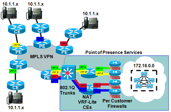
アベイラビリティ
MPLS VPN に対する Cisco IOS NAT のサポートは、Cisco IOS リリース 12.2(13)T で提供されています。MPLS をサポートするすべてのプラットフォームで利用でき、この早期導入リリース トレインで実行できます。
結論
Cisco IOS NAT には、拡張性に富んだ共有サービスをすぐに導入できる機能が用意されています。シスコは、お客様にとって重要なプロトコルをサポートする NAT アプリケーション レベル ゲートウェイ(ALG)を今後も開発し続けます。変換機能のパフォーマンス向上とハードウェア アクセラレーションにより、NAT および ALG は当面の間、許容できるソリューションを提供することができます。シスコは、関連する標準化活動やコミュニティの動きについて、常に注意を傾けています。他の標準が開発されたときには、お客様の要望、ニーズ、および用途に基づいてその使用が評価されます。
 フィードバック