シングルホーム/マルチホーム環境における、BGPを使用したロードシェアリングについて
ダウンロード オプション
偏向のない言語
この製品のドキュメントセットは、偏向のない言語を使用するように配慮されています。このドキュメントセットでの偏向のない言語とは、年齢、障害、性別、人種的アイデンティティ、民族的アイデンティティ、性的指向、社会経済的地位、およびインターセクショナリティに基づく差別を意味しない言語として定義されています。製品ソフトウェアのユーザインターフェイスにハードコードされている言語、RFP のドキュメントに基づいて使用されている言語、または参照されているサードパーティ製品で使用されている言語によりドキュメントに例外が存在する場合があります。シスコのインクルーシブ ランゲージの取り組みの詳細は、こちらをご覧ください。
翻訳について
シスコは世界中のユーザにそれぞれの言語でサポート コンテンツを提供するために、機械と人による翻訳を組み合わせて、本ドキュメントを翻訳しています。ただし、最高度の機械翻訳であっても、専門家による翻訳のような正確性は確保されません。シスコは、これら翻訳の正確性について法的責任を負いません。原典である英語版(リンクからアクセス可能)もあわせて参照することを推奨します。
内容
はじめに
このドキュメントでは、ロードシェアリングについて説明します。ロードシェアリングを使用すると、ルータで発信トラフィックと着信トラフィックを複数のパスに分散できます。
前提条件
要件
この設定を開始する前に、次の要件が満たされていることを確認してください。
-
BGP でベスト パスを選択するアルゴリズムに関する知識
使用するコンポーネント
このドキュメントの内容は、特定のソフトウェアやハードウェアのバージョンに限定されるものではありません。
このドキュメントの情報は、特定のラボ環境にあるデバイスに基づいて作成されました。このドキュメントで使用するすべてのデバイスは、クリアな(デフォルト)設定で作業を開始しています。本稼働中のネットワークでは、各コマンドによって起こる可能性がある影響を十分確認してください。
背景説明
着信および発信トラフィックパスは、静的に、または次のようなダイナミックプロトコルによって取得されます。
-
Routing Information Protocol(RIP)
-
Enhanced Interior Gateway Routing Protocol(EIGRP)
-
Open Shortest Path First(OSPF)プロトコル
デフォルトでは、Border Gateway Protocol(BGP)が単一のベスト パスを選択するだけで、ロード バランシングは実行しません。このドキュメントでは、BGPを使用したさまざまなシナリオでロードシェアリングを実行する方法について説明します。ロードバランスについての詳細は、『ロードバランスの機能のしくみ』を参照してください。
BGP ネイバーとしてのループバック アドレスとのロード シェアリング
このシナリオでは、複数の(最大 6 つの)等コスト リンクがある場合にロード シェアリングを実行する方法について説明します。リンクはローカルの自律システム(AS)の 1 つのルータと、シングルホーム接続の BGP 環境内のリモート AS の別のルータで終端されます。ネットワーク図は一例です。
ネットワーク図
このセクションでは、次のネットワーク設定を使用します。

コンフィギュレーション
このセクションでは、次の設定例を使用しています。
RouterA
interface loopback 0
 ip address 192.168.1.1 255.255.255.255

interface GigabitEthernet0/1
 ip address 10.20.20.1 255.255.255.0

interface GigabitEthernet0/0
 ip address 10.10.10.1 255.255.255.0

router bgp 11
 neighbor 192.168.2.2 remote-as 10
 neighbor 192.168.2.2 update-source loopback 0

!--- Use the IP address of the loopback interface for TCP connections.

neighbor 192.168.2.2 ebgp-multihop

!--- You must configure ebgp-multihop whenever the external BGP (eBGP) connections are not on the same network address.

router eigrp 12
 network 192.168.1.1 0.0.0.0
 network 10.0.0.0
 no auto-summary
RouterB
interface loopback 0
 ip address 192.168.2.2 255.255.255.255

interface GigabitEthernet0/1
 ip address 10.20.20.2 255.255.255.0

interface GigabitEthernet0/0
 ip address 10.10.10.2 255.255.255.0

router bgp 10
 neighbor 192.168.1.1 remote-as 11
 neighbor 192.168.1.1 update-source loopback 0

!--- Use the IP address of the loopback interface for TCP connections.

neighbor 192.168.1.1 ebgp-multihop

!--- You must configure ebgp-multihop whenever the eBGP connections are not on the same network address.

router eigrp 12
 network 192.168.2.2 0.0.0.0
 network 10.0.0.0
 no auto-summary
注:ルーティングプロトコルの代わりにスタティックルートを使用して、宛先に到達する2つの等コストパスを導入できます。しかし、この例では、ループバック情報を共有するためにEIGRPが使用されました。
確認
ここでは、設定が正常に動作していることを確認します。
Cisco CLI アナライザ(登録ユーザ専用)は、特定の show コマンドをサポートします。show コマンド出力の分析を表示するには、Cisco CLI アナライザを使用します。
show ip routeコマンドの出力には、EIGRPによって学習された192.168.2.2ネットワークへの両方のパスが表示されます。show ip bgp summaryコマンドでは、BGPネイバーがリモートルータのループバックを使用して構築されたことが示されています。tracerouteコマンドの出力は、負荷が2つのシリアルリンク間に分散されていることを示しています。このシナリオでは、パケット単位でロード シェアリングが実行されます。シリアル インターフェイスで ip route-cache コマンドを発行すると、宛先単位でロード シェアリングを実行できます。また、Cisco Express Forwarding では、パケット単位および宛先単位のロード シェアリングを設定することもできます。Cisco Express Forwarding の設定方法の詳細は、「Cisco Express Forwarding の設定」を参照してください。
RouterA#show ip route Codes: L - local, C - connected, S - static, R - RIP, M - mobile, B - BGP D - EIGRP, EX - EIGRP external, O - OSPF, IA - OSPF inter area N1 - OSPF NSSA external type 1, N2 - OSPF NSSA external type 2 E1 - OSPF external type 1, E2 - OSPF external type 2 i - IS-IS, su - IS-IS summary, L1 - IS-IS level-1, L2 - IS-IS level-2 ia - IS-IS inter area, * - candidate default, U - per-user static route o - ODR, P - periodic downloaded static route, H - NHRP, l - LISP a - application route + - replicated route, % - next hop override, p - overrides from PfR Gateway of last resort is not set 10.0.0.0/8 is variably subnetted, 4 subnets, 2 masks C 10.10.10.0/24 is directly connected, GigabitEthernet0/0 L 10.10.10.1/32 is directly connected, GigabitEthernet0/0 C 10.20.20.0/24 is directly connected, GigabitEthernet0/1 L 10.20.20.1/32 is directly connected, GigabitEthernet0/1 192.168.1.0/32 is subnetted, 1 subnets C 192.168.1.1 is directly connected, Loopback0 192.168.2.0/32 is subnetted, 1 subnets D 192.168.2.2 [90/130816] via 10.20.20.2, 00:02:01, GigabitEthernet0/1 [90/130816] via 10.10.10.2, 00:02:01, GigabitEthernet0/0 RouterA#RouterA#show ip bgp summary BGP router identifier 192.168.1.1, local AS number 11 BGP table version is 1, main routing table version 1 Neighbor V AS MsgRcvd MsgSent TblVer InQ OutQ Up/Down State/PfxRcd 192.168.2.2 4 10 20 20 1 0 0 00:15:05 0RouterA#traceroute 192.168.2.2 Type escape sequence to abort. Tracing the route to 192.168.2.2 VRF info: (vrf in name/id, vrf out name/id) 1 10.10.10.2 2 msec 10.20.20.2 2 msec 10.10.10.2 2 msec RouterA#
トラブルシュート
現在のところ、この設定に関する特定のトラブルシューティング情報はありません。
単一のローカル ルータを通じた 1 つのインターネット サービス プロバイダー(ISP)へのデュアルホーム接続時のロード シェアリング
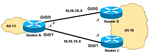
このシナリオでは、リモート AS とローカル AS 間に複数のリンクが存在する場合にロード シェアリングを実行する方法について説明します。これらのリンクはローカル AS の 1 つのルータと、シングルホーム接続の BGP 環境内のリモート AS の複数のルータで終端されます。ネットワーク図に、このようなネットワークの例を示します。
この構成例では、maximum-paths コマンドを使用します。デフォルトでは、BGP は 1 つの AS から取得した使用可能な等コスト パスの中から 1 つのベスト パスを選択します。ただし、許可されているパラレル等コスト パスの最大数は変更できます。これを変更するには、BGP 構成の下に maximum-paths paths コマンドを含めます。paths の引数として 1 ~ 6 の数字を使用します。
ネットワーク図
このセクションでは、次のネットワーク設定を使用します。
コンフィギュレーション
このセクションでは、次の設定例を使用しています。
RouterA
interface Loopback0
 ip address 192.168.1.1 255.255.255.255
!
interface GigabitEthernet0/0
 ip address 10.20.20.1 255.255.255.0
!
!
interface GigabitEthernet0/1
 ip address 10.10.10.1 255.255.255.0
!
!
router bgp 11
 neighbor 10.20.20.2 remote-as 10
 neighbor 10.10.10.2 remote-as 10
 network 192.168.1.1 mask 255.255.255.255
 maximum-paths 2

!--- This command specifies the maximum number of paths to install in the routing table for a specific destination.
RouterB
interface GigabitEthernet0/2
 ip address 172.16.2.1 255.255.255.0
!
interface GigabitEthernet0/0
 ip address 10.20.20.2 255.255.255.0
!
!
router bgp 10
 neighbor 10.20.20.1 remote-as 11
 network 172.16.2.0 mask 255.255.255.0
RouterC
interface GigabitEthernet0/2
 ip address 172.16.2.2 255.255.255.0
!
interface GigabitEthernet0/1
 ip address 10.10.10.2 255.255.255.0
!
!
router bgp 10
neighbor 10.10.10.1 remote-as 11
network 172.16.2.0 mask 255.255.255.0
確認
ここでは、設定が正常に動作していることを確認します。
Cisco CLI アナライザ(登録ユーザ専用)は、特定の show コマンドをサポートします。show コマンド出力の分析を表示するには、Cisco CLI アナライザを使用します。
show ip routeコマンドの出力には、172.16.2.0ネットワークへの両方のパスがBGPによって学習されたことが示されています。tracerouteコマンドの出力は、負荷が2つのシリアルリンク間に分散されていることを示しています。このシナリオでは、宛先単位でロード シェアリングが実行されます。show ip bgp コマンドは、172.16.2.0 ネットワークに有効なエントリを提供します。
RouterA#show ip route Codes: L - local, C - connected, S - static, R - RIP, M - mobile, B - BGP D - EIGRP, EX - EIGRP external, O - OSPF, IA - OSPF inter area N1 - OSPF NSSA external type 1, N2 - OSPF NSSA external type 2 E1 - OSPF external type 1, E2 - OSPF external type 2 i - IS-IS, su - IS-IS summary, L1 - IS-IS level-1, L2 - IS-IS level-2 ia - IS-IS inter area, * - candidate default, U - per-user static route o - ODR, P - periodic downloaded static route, H - NHRP, l - LISP a - application route + - replicated route, % - next hop override, p - overrides from PfR Gateway of last resort is not set 10.0.0.0/8 is variably subnetted, 4 subnets, 2 masks C 10.10.10.0/24 is directly connected, GigabitEthernet0/1 L 10.10.10.1/32 is directly connected, GigabitEthernet0/1 C 10.20.20.0/24 is directly connected, GigabitEthernet0/0 L 10.20.20.1/32 is directly connected, GigabitEthernet0/0 172.16.0.0/24 is subnetted, 1 subnets B 172.16.2.0 [20/0] via 10.20.20.2, 00:08:51 [20/0] via 10.10.10.2, 00:08:51 192.168.1.0/32 is subnetted, 1 subnets C 192.168.1.1 is directly connected, Loopback0RouterA#traceroute 172.16.2.2 source loopback0 Type escape sequence to abort. Tracing the route to 172.16.2.2 VRF info: (vrf in name/id, vrf out name/id) 1 10.10.10.2 3 msec 10.20.20.2 3 msec 10.10.10.2 3 msec RouterA#RouterA#show ip bgp BGP table version is 4, local router ID is 192.168.1.1 Status codes: s suppressed, d damped, h history, * valid, > best, i - internal, r RIB-failure, S Stale, m multipath, b backup-path, f RT-Filter, x best-external, a additional-path, c RIB-compressed, t secondary path, Origin codes: i - IGP, e - EGP, ? - incomplete RPKI validation codes: V valid, I invalid, N Not found Network Next Hop Metric LocPrf Weight Path *m 172.16.2.0/24 10.10.10.2 0 0 10 i *> 10.20.20.2 0 0 10 i *> 192.168.1.1/32 0.0.0.0 0 32768 i
トラブルシュート
現在のところ、この設定に関する特定のトラブルシューティング情報はありません。
複数のローカル ルータを通じた 1 つの ISP へのデュアルホーム接続時のロード シェアリング
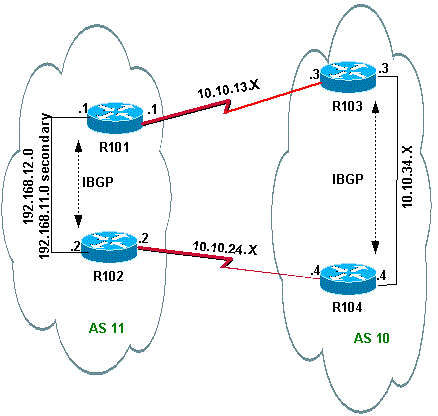
このシナリオでは、複数のローカル ルータを通じた同じ ISP への接続が複数ある場合に、ロード シェアリングを実行する方法について説明します。2 つの eBGP ピアは 2 つの個別のローカル ルータで終端されます。BGPはeBGPと内部BGP(iBGP)から学習したネットワークの中から最適なパスを1つだけ選択するため、2つのリンクでロードバランシングを行うことはできません。AS 10 への複数のパス間でのロード シェアリングが 2 番目に最適な選択肢です。このタイプのロード シェアリングでは、特定のネットワークへのトラフィックは、事前に定義されたポリシーに基づき、両方のリンクを通じて移動します。さらに、各リンクはもう一方のリンクに障害が発生した場合には、そのリンクのバックアップとして機能します。
説明を簡単にするため、AS 11のBGPルーティングポリシーを次のように想定します。
-
AS 11 は AS 10 からのローカル ルートとともに、残りのインターネット ルートのデフォルトを受け入れます。
-
発信トラフィック ポリシーは次のとおりです。
-
R101からインターネットに向かうトラフィックはすべて、R101-R103リンクを通ります。
-
R101-R103リンクに障害が発生した場合、R101からインターネットへのすべてのトラフィックはR102を経由してAS 10に向かいます。
-
同様に、R102からインターネットに向かうトラフィックはすべてR102-R104リンクを通過します。
-
R102-R104リンクに障害が発生した場合、R102からインターネットへのすべてのトラフィックはR101を経由してAS 10に向かいます。
-
-
着信トラフィック ポリシーは、次のとおりです。
-
インターネットからネットワーク192.168.11.0/24宛てのトラフィックは、R103-R101リンクから到達します。
-
インターネットからネットワーク192.168.12.0/24宛てのトラフィックは、R104-R102リンクから到達します。
-
AS 10へのリンクの1つに障害が発生した場合、もう1つのリンクはすべてのネットワーク宛てのトラフィックをインターネットからAS 11にルーティングして戻します。
-
これを実現するために、192.168.11.0はR102からR104にアナウンスされるAS_PATHよりも短いAS_PATHでR101からR103にアナウンスされます。AS 10 は R103-R101 リンクを通じてベスト パスを検索します。同様に、192.168.12.0 は R102-R104 リンクを通じて短いパスでアナウンスされます。AS 10は、AS 11の192.168.12.0にバインドされたトラフィックに対してR104-R102リンクを優先します。
発信トラフィックの場合、BGPはeBGPを通じて学習したルートに基づいてベストパスを決定します。これらのルートは iBGP を通じて取得したルートよりも優先されます。そのため、R101 は eBGP を通じて R103 から、iBGP を通じて R102 から 10.10.34.0 を取得します。内部パスよりも外部パスが選択されます。R101設定のBGPテーブルを見ると、10.10.34.0へのルートはネクストホップが10.10.13.3のR101-R103リンクを通っています。R102では、10.10.34.0に向かうルートはR102-R104リンクを通り、ネクストホップは10.10.24.4です。これにより、10.10.34.0宛てのトラフィックのロードシェアリングが実現します。同様の理由が、R101とR102のデフォルトルートにも当てはまります。BGP パスの選択基準の詳細については、『BGP でベスト パスを選択するアルゴリズム』を参照してください。
ネットワーク図
このセクションでは、次のネットワーク設定を使用します。
コンフィギュレーション
このセクションでは、次の設定例を使用しています。
R101
hostname R101
!
interface Ethernet0/0
 ip address 192.168.11.1 255.255.255.0 secondary
 ip address 192.168.12.1 255.255.255.0
!
interface Serial8/0
 ip address 10.10.13.1 255.255.255.0
!
router bgp 11
 no synchronization
 bgp log-neighbor-changes
 network 192.168.11.0
 network 192.168.12.0
 neighbor 10.10.13.3 remote-as 10
 neighbor 10.10.13.3 route-map R101-103-MAP out

!--- The AS_PATH is increased for 192.168.12.0.

 neighbor 192.168.12.2 remote-as 11
 neighbor 192.168.12.2 next-hop-self
 maximum-paths 2
 no auto-summary
!
access-list 1 permit 192.168.12.0
access-list 2 permit 192.168.11.0
route-map R101-103-MAP permit 10
 match ip address 1
 set as-path prepend 11 11 11
!
route-map R101-103-MAP permit 20
 match ip address 2
R102
hostname R102
!
interface Ethernet0/0
 ip address 192.168.11.2 255.255.255.0 secondary
 ip address 192.168.12.2 255.255.255.0
!
interface Serial8/0
 ip address 10.10.24.2 255.255.255.0
!
router bgp 11
 no synchronization
 bgp log-neighbor-changes
 network 192.168.11.0
 network 192.168.12.0
 neighbor 10.10.24.4 remote-as 10
 neighbor 10.10.24.4 route-map R102-104-MAP out

!--- The AS_PATH is increased for 192.168.11.0.

 neighbor 192.168.12.1 remote-as 11
 neighbor 192.168.12.1 next-hop-self
 no auto-summary
!
access-list 1 permit 192.168.11.0
access-list 2 permit 192.168.12.0
route-map R102-104-MAP permit 10
 match ip address 1
 set as-path prepend 11 11 11
!
route-map R102-104-MAP permit 20
 match ip address 2
R103
hostname R103
!
interface Ethernet0/0
 ip address 10.10.34.3 255.255.255.0
!
interface Serial8/0
 ip address 10.10.13.3 255.255.255.0
!
router bgp 10
no synchronization
 bgp log-neighbor-changes
 network 10.10.34.0 mask 255.255.255.0
 neighbor 10.10.13.1 remote-as 11
 neighbor 10.10.13.1 default-originate
 neighbor 10.10.34.4 remote-as 10
 neighbor 10.10.34.4 next-hop-self
 no auto-summary
R104
hostname R104
!
interface Ethernet0/0
 ip address 10.10.34.4 255.255.255.0
!
interface Serial8/0
 ip address 10.10.24.4 255.255.255.0
!
router bgp 10
 no synchronization
 bgp log-neighbor-changes
 neighbor 10.10.24.2 remote-as 11
 neighbor 10.10.24.2 default-originate
 neighbor 10.10.34.3 remote-as 10
 neighbor 10.10.34.3 next-hop-self
 no auto-summary
確認
このセクションでは、設定が正常に動作しているかどうかを確認する際に役立つ情報を示しています。
特定のshowコマンドは、Cisco CLI Analyzer(登録ユーザ専用)でサポートされています。このユーティリティを使用すると、showコマンド出力を分析できます。
AS 11 と AS 10 間の両方のリンクが稼動している場合の検証
発信トラフィックの検証
注:show ip bgpコマンド出力の大なり記号(>)は、使用可能なパス間の当該ネットワークに使用するベストパスを表します。詳細については、BGP ベスト パス選択アルゴリズムを参照してください。
R101のBGPテーブルは、インターネットへのすべての発信トラフィックがR101-R103リンクを経由するベストパスを示しています。show ip route コマンドの出力では、ルーティング テーブルのルートを確認します。
R101#show ip bgp

BGP table version is 5, local router ID is 192.168.12.1
Status codes: s suppressed, d damped, h history, * valid, > best, i - internal
Origin codes: i - IGP, e - EGP, ? - incomplete

   Network          Next Hop            Metric LocPrf Weight Path
* i0.0.0.0          192.168.12.2                  100      0 10 i
*>                  10.10.13.3                             0 10 i
!--- This is the next hop of R103.

* i10.10.34.0/24    192.168.12.2                  100      0 10 i
*>                  10.10.13.3               0             0 10 i
!--- This is the next hop of R103.
* i192.168.11.0     192.168.12.2             0    100      0 i
*>                  0.0.0.0                  0         32768 i
* i192.168.12.0     192.168.12.2             0    100      0 i
*>                  0.0.0.0                  0         32768 i

R101#show ip route

!--- Output suppressed.

Gateway of last resort is 10.10.13.3 to network 0.0.0.0

C    192.168.12.0/24 is directly connected, Ethernet0/0
C    192.168.11.0/24 is directly connected, Ethernet0/0
     10.0.0.0/24 is subnetted, 2 subnets
C       10.10.13.0 is directly connected, Serial8/0
B       10.10.34.0 [20/0] via 10.10.13.3, 00:08:53
!--- This is the next hop of R103.

B*   0.0.0.0/0 [20/0] via 10.10.13.3, 00:08:53
!--- This is the next hop of R103.
次に、R102 の BGP とルーティング テーブルを示します。ポリシーに基づいて、R102はすべてのトラフィックをR102-R104リンク経由でAS 10にルーティングします。
R102#show ip bgp

BGP table version is 7, local router ID is 192.168.12.2
Status codes: s suppressed, d damped, h history, * valid, > best, i - internal
Origin codes: i - IGP, e - EGP, ? - incomplete

   Network          Next Hop            Metric LocPrf Weight Path
*> 0.0.0.0          10.10.24.4                             0 10 i
!--- This is the next hop of R104.

* i                 192.168.12.1                  100      0 10 i
*> 10.10.34.0/24    10.10.24.4                             0 10 i
!--- This is the next hop of R104.

* i                 192.168.12.1             0    100      0 10 i
* i192.168.11.0     192.168.12.1             0    100      0 i
*>                  0.0.0.0                  0         32768 i
* i192.168.12.0     192.168.12.1             0    100      0 i
*>                  0.0.0.0                  0         32768 i

R102#show ip route

!--- Output suppressed.

Gateway of last resort is 10.10.24.4 to network 0.0.0.0

C    192.168.12.0/24 is directly connected, Ethernet0/0
C    192.168.11.0/24 is directly connected, Ethernet0/0
     10.0.0.0/24 is subnetted, 2 subnets
C       10.10.24.0 is directly connected, Serial8/0
B       10.10.34.0 [20/0] via 10.10.24.4, 00:11:21
!--- This is the next hop of R104.

B*   0.0.0.0/0 [20/0] via 10.10.24.4, 00:11:21
!--- This is the next hop of R104.
AS 10 から AS 11 への着信トラフィックの検証
ネットワーク192.168.11.0と192.168.12.0はAS 11に属しています。ポリシーに基づいて、AS 11はネットワーク192.168.11.0宛てのトラフィックに対してはR103-R101リンクを優先し、ネットワーク192.168.12.0宛てのトラフィックに対してはR104-R102リンクを優先します。
R103#show ip bgp

BGP table version is 4, local router ID is 10.10.34.3
Status codes: s suppressed, d damped, h history, * valid, > best, i - internal
Origin codes: i - IGP, e - EGP, ? - incomplete

   Network          Next Hop            Metric LocPrf Weight Path
*> 10.10.34.0/24    0.0.0.0                  0         32768 i
*> 192.168.11.0     10.10.13.1               0             0 11 i
!--- The next hop is R101.
*  192.168.12.0     10.10.13.1               0             0 11 11 11 11 i
*>i                 10.10.34.4               0    100      0 11 i
!--- The next hop is R104.


R103#show ip route

!--- Output suppressed.
Gateway of last resort is not set

B    192.168.12.0/24 [200/0] via 10.10.34.4, 00:04:46
!--- The next hop is R104.

B    192.168.11.0/24 [20/0] via 10.10.13.1, 00:04:46
!--- The next hop is R101.

     10.0.0.0/24 is subnetted, 2 subnets
C       10.10.13.0 is directly connected, Serial8/0
C       10.10.34.0 is directly connected, Ethernet0/0
R103上のネットワーク192.168.11.0のベストパスはR103-R101リンクを経由し、ネットワーク192.168.12.0のベストパスはR104を経由してAS 11に到達します。この場合、最短パス長によってベストパスが決定されます。
同様に、R104 では、BGP とルーティング テーブルは次のようになります。
R104#show ip bgp

BGP table version is 13, local router ID is 10.10.34.4
Status codes: s suppressed, d damped, h history, * valid, > best, i - internal
Origin codes: i - IGP, e - EGP, ? - incomplete

   Network          Next Hop            Metric LocPrf Weight Path
*>i10.10.34.0/24    10.10.34.3               0    100      0 i
*>i192.168.11.0     10.10.34.3               0    100      0 11 i
*                   10.10.24.2               0             0 11 11 11 11 i
*> 192.168.12.0     10.10.24.2               0             0 11 i

R104#show ip route

!--- Output suppressed.
Gateway of last resort is not set

B    192.168.12.0/24 [20/0] via 10.10.24.2, 00:49:06
!--- The next hop is R102.

B    192.168.11.0/24 [200/0] via 10.10.34.3, 00:07:36
!--- The next hop is R103.

     10.0.0.0/24 is subnetted, 2 subnets
C       10.10.24.0 is directly connected, Serial8/0
C       10.10.34.0 is directly connected, Ethernet0/0
R101-R103 リンクに障害が発生した場合の検証
R101-R103リンクに障害が発生すると、すべてのトラフィックはR102を経由して再ルーティングする必要があります。次の図に、この変更を示します。
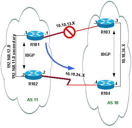
この状況をシミュレーションするため、R103 の R103-R101 リンクをシャットダウンします。
R103(config)#interface serial 8/0
R103(config-if)#shutdown

*May 1 00:52:33.379: %BGP-5-ADJCHANGE: neighbor 10.10.13.1 Down Interface flap
*May 1 00:52:35.311: %LINK-5-CHANGED: Interface Serial8/0, changed state to administratively down
*May 1 00:52:36.127: %LINEPROTO-5-UPDOWN: Line protocol on Interface Serial8/0, changed state to down
AS 10 への発信ルートを確認します。
R101#show ip bgp

BGP table version is 17, local router ID is 192.168.12.1
Status codes: s suppressed, d damped, h history, * valid, > best, i - internal
Origin codes: i - IGP, e - EGP, ? - incomplete

   Network          Next Hop            Metric LocPrf Weight Path
*>i0.0.0.0          192.168.12.2                  100      0 10 i
!--- This is the next hop of R102.
*>i10.10.34.0/24    192.168.12.2                  100      0 10 i
!--- This is the next hop of R102.

* i192.168.11.0     192.168.12.2             0    100      0 i
*>                  0.0.0.0                  0         32768 i
* i192.168.12.0     192.168.12.2             0    100      0 i
*>                  0.0.0.0                  0         32768 i

R101#show ip route

!--- Output suppressed.

Gateway of last resort is 192.168.12.2 to network 0.0.0.0

C    192.168.12.0/24 is directly connected, Ethernet0/0
C    192.168.11.0/24 is directly connected, Ethernet0/0
     10.0.0.0/24 is subnetted, 1 subnets
B       10.10.34.0 [200/0] via 192.168.12.2, 00:01:34
B*   0.0.0.0/0 [200/0] via 192.168.12.2, 00:01:34

!--- All outbound traffic goes through R102.

R102#show ip route

!--- Output suppressed.

Gateway of last resort is 10.10.24.4 to network 0.0.0.0

C    192.168.12.0/24 is directly connected, Ethernet0/0
 C    192.168.11.0/24 is directly connected, Ethernet0/0
     10.0.0.0/24 is subnetted, 2 subnets
C       10.10.24.0 is directly connected, Serial8/0
B       10.10.34.0 [20/0] via 10.10.24.4, 00:13:22
B*   0.0.0.0/0 [20/0] via 10.10.24.4, 00:55:22

!--- All outbound traffic on R102 goes through R104.
R101-R103 がダウンした場合の着信トラフィック ルートを確認します。
R103#show ip bgp

BGP table version is 6, local router ID is 10.10.34.3
Status codes: s suppressed, d damped, h history, * valid, > best, i - internal
Origin codes: i - IGP, e - EGP, ? - incomplete

   Network          Next Hop            Metric LocPrf Weight Path
*> 10.10.34.0/24    0.0.0.0                  0         32768 i
*>i192.168.11.0     10.10.34.4               0    100      0 11 11 11 11 i
*>i192.168.12.0     10.10.34.4               0    100      0 11 i

R103#show ip route

!--- Output suppressed.
Gateway of last resort is not set

B    192.168.12.0/24 [200/0] via 10.10.34.4, 00:14:55
!--- The next hop is R104.

B    192.168.11.0/24 [200/0] via 10.10.34.4, 00:05:46
!--- The next hop is R104.
     10.0.0.0/24 is subnetted, 1 subnets
C       10.10.34.0 is directly connected, Ethernet0/0
R104 で、192.168.11.0 と 192.168.12.0 へのトラフィックは R104-R102 リンクを通過します。
R104#show ip route

!--- Output suppressed.

Gateway of last resort is not set

B    192.168.12.0/24 [20/0] via 10.10.24.2, 00:58:35
!--- The next hop is R102.

B    192.168.11.0/24 [20/0] via 10.10.24.2, 00:07:57
!--- The next hop is R102.

     10.0.0.0/24 is subnetted, 2 subnets
C       10.10.24.0 is directly connected, Serial8/0
C       10.10.34.0 is directly connected, Ethernet0/0
トラブルシュート
現在のところ、この設定に関する特定のトラブルシューティング情報はありません。
単一のローカル ルータを通じた 2 つの ISP へのマルチホーム接続時のロード シェアリング
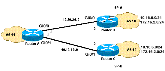
このシナリオでは、ロード バランシングはマルチスレッド環境でのオプションではありません。そのため、実行できるのはロード シェアリングのみです。BGPは異なるASから学習したBGPルートの中から宛先への最適なパスを1つだけ選択するため、ロードバランシングは実行できません。これは、1.0.0.xから128.0.0.xまでの範囲のルートについてはISP(A)から学習した方に大きいメトリックを設定し、それ以外のルートについてはISP(B)から学習した方に大きいメトリックを設定するというものです。ネットワーク図は一例です。
詳細は、「2 つの異なるサービス プロバイダー(マルチホーミング)を使用した BGP の設定例」を参照してください。
ネットワーク図
このセクションでは、次のネットワーク設定を使用します。
コンフィギュレーション
このセクションでは、次の設定例を使用しています。
RouterA
interface GigabitEthernet0/0
 ip address 10.20.20.1 255.255.255.0

interface GigabitEthernet0/1
 ip address 10.10.10.1 255.255.255.0

router bgp 11
 neighbor 10.20.20.2 remote-as 10
 neighbor 10.20.20.2 route-map UPDATES-1 in

!--- This allows only the networks up to 128.0.0.x.

neighbor 10.10.10.2 remote-as 12
neighbor 10.10.10.2 route-map UPDATES-2 in

!--- This allows anything above the 128.0.0.x network.

route-map UPDATES-1 permit 10
 match ip address 1
 set weight 100

route-map UPDATES-1 permit 20
 match ip address 2

route-map UPDATES-2 permit 10
 match ip address 1

route-map UPDATES-2 permit 20
 match ip address 2
 set weight 100

access-list 1 permit 0.0.0.0 127.255.255.255
access-list 2 deny 0.0.0.0 127.255.255.255
access-list 2 permit any
RouterB
interface GigabitEthernet0/2
 ip address 172.16.2.1 255.255.255.0

interface GigabitEthernet0/3
 ip address 10.16.6.1 255.255.255.0

interface GigabitEthernet0/0
 ip address 10.20.20.2 255.255.255.0

router bgp 10
 neighbor 10.20.20.1 remote-as 11
 network 172.16.2.0 mask 255.255.255.0
 network 10.16.6.0 mask 255.255.255.0
RouterC
interface GigabitEthernet0/3
 ip address 10.16.6.2 255.255.255.0

interface GigabitEthernet0/2
 ip address 172.16.2.2 255.255.255.0

interface GigabitEthernet0/1
 ip address 10.10.10.2 255.255.255.0

router bgp 12
 neighbor 10.10.10.1 remote-as 11
 network 172.16.2.0 mask 255.255.255.0
 network 10.16.6.0 mask 255.255.255.0
確認
ここでは、設定が正常に動作していることを確認します。
Cisco CLI アナライザ(登録ユーザ専用)は、特定の show コマンドをサポートします。show コマンド出力の分析を表示するには、Cisco CLI アナライザを使用します。
show ip routeコマンドの出力とtracerouteコマンドの出力には、128.0.0.xよりも低いネットワークが10.20.20.2を経由してルータAから出ることが示されています。このルートは、シリアル 0 インターフェイス外のネクスト ホップです。残りのネットワークは、シリアル 1 インターフェイス外のネクスト ホップである 10.10.10.2 から通り抜けます。
RouterA#show ip route
!--- Output suppressed.
Gateway of last resort is not set
B 172.16.2.0/24 [20/0] via 10.10.10.2, 00:13:16
!--- This is the next hop out through GigabitEthernet0/0.
B 10.16.6.0/24 [20/0] via 10.20.20.2, 00:13:16 !--- This is the next hop out through GigabitEthernet0/1.
!--- Output suppressed.RouterA#show ip cef 172.16.2.0 172.16.2.0/24 nexthop 10.10.10.2 GigabitEthernet0/1 RouterA#show ip cef 10.16.6.0 10.16.6.0/24 nexthop 10.20.20.2 GigabitEthernet0/0RouterA#show ip bgp BGP table version is 10, local router ID is 192.168.1.1 Status codes: s suppressed, d damped, h history, * valid, > best, i - internal, r RIB-failure, S Stale, m multipath, b backup-path, f RT-Filter, x best-external, a additional-path, c RIB-compressed, t secondary path, Origin codes: i - IGP, e - EGP, ? - incomplete RPKI validation codes: V valid, I invalid, N Not found Network Next Hop Metric LocPrf Weight Path *> 10.16.6.0/24 10.20.20.2 0 100 10 i * 10.10.10.2 0 0 12 i * 172.16.2.0/24 10.20.20.2 0 0 10 i *> 10.10.10.2 0 100 12 i *> 192.168.1.1/32 0.0.0.0 0 32768 iRouterA#traceroute 172.16.2.1 source loopback0 Type escape sequence to abort. Tracing the route to 172.16.2.1 VRF info: (vrf in name/id, vrf out name/id) 1 10.10.10.2 2 msec 3 msec 2 msec 2 172.16.2.1 [AS 12] 3 msec 3 msec * RouterA#traceroute 10.16.6.1 source loopback0 Type escape sequence to abort. Tracing the route to 10.16.6.1 VRF info: (vrf in name/id, vrf out name/id) 1 10.20.20.2 3 msec 2 msec * RouterA#
トラブルシュート
現在のところ、この設定に関する特定のトラブルシューティング情報はありません。
複数のローカル ルータを通じた 2 つの ISP へのマルチホーム接続時のロード シェアリング
2 つの ISP が存在するマルチホーム環境ではロード バランシングは不可能です。BGPは、異なるASから学習したBGPパスの中から、宛先への最適なパスを1つだけ選択するため、ロードバランシングは不可能になります。しかし、次のマルチホーム接続の BGP ネットワークではロード シェアリングが可能です。あらかじめ定められたポリシーに基づき、さまざまな BGP 属性でトラフィック フローが制御されます。
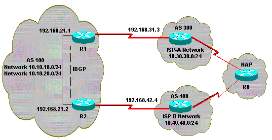
このセクションでは、最も頻繁に使用されるマルチホーム設定について説明します。この設定で、ロード シェアリングの実現方法を示します。ネットワーク図を参照してください。この図では、AS 100 のマルチホームで信頼性とロード シェアリングを実現します。
注:この例のIPアドレスは、プライベートアドレス空間に関するRFC 1918標準に準拠しています。
説明を簡単にするため、AS 100のBGPルーティングポリシーを次のように想定します。
-
AS 100は、両方のプロバイダーからのローカルルートと、他のインターネットルートのデフォルトを受け入れます。
-
発信トラフィック ポリシーは次のとおりです。
-
AS 300宛てのトラフィックは、R1-ISP(A)リンクを通過します。
-
AS 400宛てのトラフィックは、R2-ISP(B)リンクを通過します。
-
その他のトラフィックはすべて、R1-ISP(A)リンクを経由するデフォルトルート0.0.0.0を優先します。
-
R1-ISP(A)リンクに障害が発生した場合、すべてのトラフィックはR2-ISP(B)リンクを通過します。
-
-
着信トラフィック ポリシーは、次のとおりです。
-
インターネットからネットワーク10.10.10.0/24宛てのトラフィックは、ISP(A)- R1リンクから到達します。
-
インターネットからネットワーク10.10.20.0/24宛てのトラフィックは、ISP(B)- R2リンクから到達します。
-
一方のISPに障害が発生すると、もう一方のISPはすべてのネットワークのトラフィックをインターネットからAS 100にルーティングして戻します。
-
ネットワーク図
このセクションでは、次のネットワーク設定を使用します。
コンフィギュレーション
このセクションでは、次の設定例を使用しています。
R2
interface Ethernet0
 ip address 192.168.21.2 255.255.255.0
 !
interface Serial0
  ip address 192.168.42.2 255.255.255.0
router bgp 100
 no synchronization
 bgp log-neighbor-changes

!--- The next two lines announce the networks to BGP peers.

 network 10.10.10.0 mask 255.255.255.0
 network 10.10.20.0 mask 255.255.255.0

!--- The next line configures iBGP on R1.

  neighbor 192.168.21.1 remote-as 100
  neighbor 192.168.21.1 next-hop-self

!--- The next line configures eBGP with ISP(B).

 neighbor 192.168.42.4 remote-as 400

!--- This is the incoming policy route map for the application of attributes to specific routes.

 neighbor 192.168.42.4 route-map AS-400-INCOMING in

!--- This is the outgoing policy route map for the application of attributes to specific routes.

 neighbor 192.168.42.4 route-map AS-400-OUTGOING out
 no auto-summary

!--- This line sets the AS path access list, it permits all routes within the routing domain of the provider.

ip as-path access-list 1 permit ^400$

!--- These two lines set the access list.

access-list 10 permit 10.10.10.0 0.0.0.255
access-list 20 permit 10.10.20.0 0.0.0.255

!--- The next three lines configure LOCAL_PREF for routes that match AS path access list 1.

route-map AS-400-INCOMING permit 10
 match as-path 1
 set local-preference 150

!--- Here, the route map prepends AS 100 to BGP updates for networks that are permitted by access list 10.

route-map AS-400-OUTGOING permit 10
 match ip address 10
 set as-path prepend 100

!--- This line announces the network that is permitted by access list 20 without any changes in BGP attributes.

route-map AS-400-OUTGOING permit 20
 match ip address 20
R1
interface Serial0/0
 ip address 192.168.31.1 255.255.255.0
!
interface Ethernet1/0
 ip address 192.168.21.1 255.255.255.0
!
router bgp 100
 no synchronization
 bgp log-neighbor-changes
 network 10.10.10.0 mask 255.255.255.0
 network 10.10.20.0 mask 255.255.255.0

!--- IBGP peering with R2

neighbor 192.168.21.2 remote-as 100
neighbor 192.168.21.2 next-hop-self

!--- This line sets eBGP peering with ISP(A).

neighbor 192.168.31.3 remote-as 300

!--- This is the incoming policy route map for the application of attributes to specific routes.

 neighbor 192.168.31.3 route-map AS-300-INCOMING in

!--- This is the outgoing policy route map for the application of attributes to specific routes.

neighbor 192.168.31.3 route-map AS-300-OUTGOING out
 no auto-summary

!--- This line sets the AS path access list, it permits all routes within the routing domain of the provider.

ip as-path access-list 1 permit ^300$

!--- These two lines set the IP access list.

access-list 10 permit 10.10.20.0 0.0.0.255
access-list 20 permit 10.10.10.0 0.0.0.255

!--- The next three lines configure LOCAL_PREF for routes that match AS path access list 1.

route-map AS-300-INCOMING permit 10
 match as-path 1
 set local-preference 200

!--- Here, the route map prepends AS 100 to BGP updates for networks that are permitted by access list 10.

route-map AS-300-OUTGOING permit 10
 match ip address 10
 set as-path prepend 100

!--- This line announces the network that is permitted by access list 20 without any changes in BGP attributes.

route-map AS-300-OUTGOING permit 20
 match ip address 20
!
確認
ここでは、設定が正常に動作していることを確認します。
Cisco CLI アナライザ(登録ユーザ専用)は、特定の show コマンドをサポートします。show コマンド出力の分析を表示するには、Cisco CLI アナライザを使用します。
発着信ポリシーが機能していることを確認するため、show ip bgp コマンドを発行します。
注:show ip bgp出力の大なり記号(>)は、使用可能なパスの中で、そのネットワークに使用するベストパスを表します。詳細については、BGP ベスト パス選択アルゴリズムを参照してください。
R1#show ip bgp

BGP table version is 6, local router ID is 192.168.31.1
Status codes: s suppressed, d damped, h history, * valid, > best, i - internal
Origin codes: i - IGP, e - EGP, ? - incomplete

BGP table version is 6, local router ID is 192.168.31.1
Status codes: s suppressed, d damped, h history, * valid, > best, i - internal
Origin codes: i - IGP, e - EGP, ? - incomplete

Network          Next Hop            Metric LocPrf Weight Path
*> 0.0.0.0          192.168.31.3                  200      0 300 i

!--- This line shows that the default route 0.0.0.0/0 is preferred through AS 300, ISP(A).

* i10.10.10.0/24    192.168.21.2             0    100      0 i
*>                  0.0.0.0                  0         32768 i
* i10.10.20.0/24    192.168.21.2             0    100      0 i
*>                  0.0.0.0                  0         32768 i
*> 10.30.30.0/24    192.168.31.3             0    200      0 300 i
*>i10.40.40.0/24    192.168.21.2             0    150      0 400 i


!--- The route to network 10.30.30.0/24 (AS 300) is preferred through the R1-ISP(A) link.
!--- The route to network 10.40.40.0/24 (AS 400) is preferred through the R2-ISP(B) link.
次に、R2 での show ip bgp の出力を示します。
R2#show ip bgp

BGP table version is 8, local router ID is 192.168.42.2
Status codes: s suppressed, d damped, h history, * valid, > best, i - internal
Origin codes: i - IGP, e - EGP, ? - incomplete

   Network          Next Hop            Metric LocPrf Weight Path
*  0.0.0.0          192.168.42.4                  150      0 400 i
*>i                 192.168.21.1                  200      0 300 i

!--- This line shows that the default route 0.0.0.0/0 is preferred through AS 300, through the R2-ISP(B) link.

*> 10.10.10.0/24    0.0.0.0                  0         32768 i
* i                 192.168.21.1             0    100      0 i
*> 10.10.20.0/24    0.0.0.0                  0         32768 i
* i                 192.168.21.1             0    100      0 i
*>i10.30.30.0/24    192.168.21.1             0    200      0 300 i
*> 10.40.40.0/24    192.168.42.4             0    150      0 400 i

!--- The route to network 10.30.30.0/24 (AS 300) is preferred through the R1-ISP(A) link.
!--- The route to network 10.40.40.0/24 (AS 400) is preferred through the R2-ISP(B) link.
ルータ6でshow ip bgpコマンドを発行して、ネットワーク10.10.10.0/24および10.10.20.0/24の着信ポリシーを確認します。
R6#show ip bgp

BGP table version is 15, local router ID is 192.168.64.6
Status codes: s suppressed, d damped, h history, * valid, > best, i - internal
Origin codes: i - IGP, e - EGP, ? - incomplete

   Network          Next Hop            Metric LocPrf Weight Path
*> 10.10.10.0/24    192.168.63.3                           0 300 100 100 i

!--- This line shows that network 10.10.10.0/24 is routed through AS 300
!--- with the ISP(A)-R1 link.

*                   192.168.64.4                           0 400 100 100 100 i
*  10.10.20.0/24    192.168.63.3                           0 300 100 100 i
*>                  192.168.64.4                           0 400 100 i

!--- This line shows that network 10.10.20.0/24 is routed through AS 400
!--- with the ISP(B)-R2 link.

*> 10.30.30.0/24    192.168.63.3             0             0 300 i
*> 10.40.40.0/24    192.168.64.4             0             0 400 i
R1 の R1-ISP(A) リンクをシャットダウンし、BGP テーブルを観察します。インターネットへのすべてのトラフィックは、R2-ISP(B)リンクを介してルーティングされると予想されます。
R1(config)#interface serial 0/0
R1(config-if)#shutdown

*May  2 19:00:47.377: %BGP-5-ADJCHANGE: neighbor 192.168.31.3 Down Interface flap
*May  2 19:00:48.277: %LINK-5-CHANGED: Interface Serial0/0, changed state to
 administratively  down
*May 23 12:00:51.255: %LINEPROTO-5-UPDOWN: Line protocol on Interface Serial0, changed
 state to down

R1#show ip bgp

BGP table version is 12, local router ID is 192.168.31.1
Status codes: s suppressed, d damped, h history, * valid, > best, i - internal
Origin codes: i - IGP, e - EGP, ? - incomplete

   Network          Next Hop            Metric LocPrf Weight Path
*>i0.0.0.0          192.168.21.2                  150      0 400 i

!--- The best default path is now through the R2-ISP(B) link.

* i10.10.10.0/24    192.168.21.2             0    100      0 i
*>                  0.0.0.0                  0         32768 i
* i10.10.20.0/24    192.168.21.2             0    100      0 i
*>                  0.0.0.0                  0         32768 i
*>i10.40.40.0/24    192.168.21.2             0    150      0 400 i

R2#show ip bgp

BGP table version is 14, local router ID is 192.168.42.2
Status codes: s suppressed, d damped, h history, * valid, > best, i - internal
Origin codes: i - IGP, e - EGP, ? - incomplete

   Network          Next Hop            Metric LocPrf Weight Path
*> 0.0.0.0          192.168.42.4                  150      0 400 i

!--- The best default route is now through ISP(B) with a local preference of 150.

* i10.10.10.0/24    192.168.21.1             0    100      0 i
*>                  0.0.0.0                  0         32768 i
* i10.10.20.0/24    192.168.21.1             0    100      0 i
*>                  0.0.0.0                  0         32768 i
*> 10.40.40.0/24    192.168.42.4             0    150      0 400 i
ルータ 6 のネットワーク 10.10.10.0/24 のルータを確認します。
R6#show ip bgp

BGP table version is 14, local router ID is 192.168.64.6
Status codes: s suppressed, d damped, h history, * valid, > best, i - internal
Origin codes: i - IGP, e - EGP, ? - incomplete

   Network          Next Hop            Metric LocPrf Weight Path
*> 10.10.10.0/24    192.168.64.4                           0 400 100 100 i

!--- Network 10.10.10.0 is reachable through ISP(B), which announced the network with AS path prepend.

*> 10.10.20.0/24    192.168.64.4                           0 400 100 i

*> 10.30.30.0/24    192.168.63.3             0             0 300 i
*> 10.40.40.0/24    192.168.64.4             0             0 400 i
トラブルシュート
現在のところ、この設定に関する特定のトラブルシューティング情報はありません。
関連情報
更新履歴
| 改定 | 発行日 | コメント |
|---|---|---|
3.0 |
30-Aug-2023 |
タイトル、背景情報、スタイルの要件、および書式を更新。 |
2.0 |
21-Jul-2022 |
再認定 |
1.0 |
10-Dec-2001 |
初版 |
 フィードバック