ポリシー ルーティングについて
概要
ポリシー ベース ルーティングは、ネットワーク管理者が定義したポリシーに基づいてデータ パケットを転送およびルーティングするためのツールを提供します。事実上、これは、ルーティング プロトコルの決定をポリシーがオーバーライドするための方法です。ポリシー ベース ルーティングには、アクセス リスト、パケット サイズ、または他の基準に基づいて選択的にポリシーを適用するための機能が含まれています。実行されるアクションには、ユーザ定義のルートでのパケットのルーティング、優先順位や ToS ビットなどの設定を含めることができます。
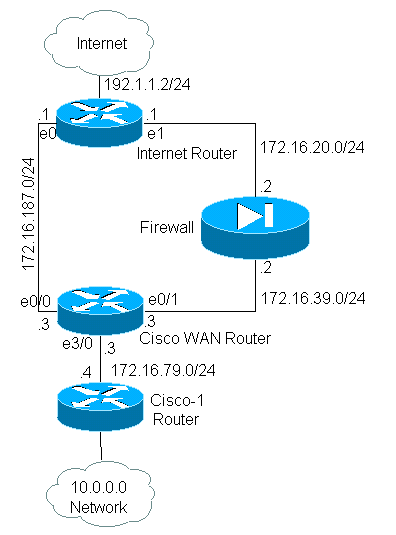
このドキュメントでは、ファイアウォールを使用して、10.0.0.0/8プライベートアドレスをサブネット172.16.255.0/24に属するインターネットでルーティング可能なアドレスに変換しています。次の図を参照してください。
詳細については、『ポリシー ルーティングについて』を参照してください。
前提条件
要件
このドキュメントに特有の要件はありません。
使用するコンポーネント
このドキュメントは、特定のハードウェアやソフトウェアのバージョンに限定されるものではありません。
このドキュメントの情報は、次のソフトウェアおよびハードウェアのバージョンに基づいています。
-
Cisco IOS® Software リリース 12.3(3)
-
Cisco 2500 シリーズ ルータ
このマニュアルの情報は、特定のラボ環境に置かれたデバイスに基づいて作成されました。このドキュメントで使用するすべてのデバイスは、初期(デフォルト)設定の状態から起動しています。実稼動中のネットワークで作業をしている場合、実際にコマンドを使用する前に、その潜在的な影響について理解しておく必要があります。
表記法
ドキュメント表記の詳細は、『シスコ テクニカル ティップスの表記法』を参照してください。
設定
この例において、通常のルーティングでは、10.0.0.0/8 ネットワークからインターネットに送信されるすべてのパケットが、(サブネット 172.16.187.0/24 を経由して)Cisco WAN ルータのインターフェイス イーサネット 0/0 を経由するパスを、最小メトリックの最適なパスとして利用します。ポリシー ベース ルーティングの場合は、これらのパケットがファイアウォールからインターネットまでのパスを利用するように、ユーザはポリシー ルーティングを設定して、通常のルーティング動作を上書きする必要があります。ファイアウォールは 10.0.0.0/8 ネットワークからインターネットに送信されるすべてのパケットを変換しますが、この作業はポリシー ルーティングの動作に必要ありません。
ネットワーク図

ファイアウォールの設定
次のファイアウォール設定は、完全な概念を示すために記載されています。ただし、このドキュメントで説明するポリシー ルーティングの問題とは関係ありません。この例のファイアウォールは、PIX やその他のファイアウォール デバイスに簡単に置き換えられます。
!
ip nat pool net-10 172.16.255.1 172.16.255.254 prefix-length 24
ip nat inside source list 1 pool net-10
!
interface Ethernet0
 ip address 172.16.20.2 255.255.255.0
 ip nat outside
!
interface Ethernet1
 ip address 172.16.39.2 255.255.255.0
 ip nat inside
!
router eigrp 1
 redistribute static
 network 172.16.0.0
 default-metric 10000 100 255 1 1500
!
ip route 172.16.255.0 255.255.255.0 Null0
access-list 1 permit 10.0.0.0 0.255.255.255
!
end
ip nat に関連するコマンドの詳細については、『IP アドレッシング コマンドおよびサービス コマンド』を参照してください。
この例では、Cisco WAN ルータは、10.0.0.0/8 ネットワークから送信された IP パケットが、ファイアウォールを経由して送信されるようにルーティングするポリシーを実行しています。次の設定には、10.0.0.0/8 ネットワークから送信されるパケットをファイアウォールへ送信する、access-list ステートメントが含まれています。
Cisco_WAN_Router の設定
!
interface Ethernet0/0
 ip address 172.16.187.3 255.255.255.0
 no ip directed-broadcast
!
interface Ethernet0/1
 ip address 172.16.39.3 255.255.255.0
 no ip directed-broadcast
!
interface Ethernet3/0
 ip address 172.16.79.3 255.255.255.0
 no ip directed-broadcast
 ip policy route-map net-10
!
router eigrp 1
 network 172.16.0.0
!

access-list 111 permit ip 10.0.0.0 0.255.255.255 any
!
route-map net-10 permit 10
 match ip address 111
 set interface Ethernet0/1
!
route-map net-10 permit 20
!
end
route-map に関連するコマンドの詳細については、route-map コマンドのドキュメントを参照してください。
注:access-listコマンドのlogキーワードは、PBRではサポートされていません。log キーワードを設定すると、ヒットが表示されなくなります。
Cisco-1 ルータの設定
!
version 12.3

!

interface Ethernet0


!-- Interface connecting to 10.0.0.0 network


ip address 10.1.1.1 255.0.0.0


!
interface Ethernet1


!-- Interface connecting to Cisco_Wan_Router

ip address 172.16.79.4 255.255.255.0

!
router eigrp 1
network 10.0.0.0
network 172.16.0.0
no auto-summary
!


!---Output Suppressed
Internet_Router の設定
!
version 12.3

!
interface Ethernet1


!-- Interface connecting to Firewall


ip address 172.16.20.1 255.255.255.0


interface Serial0


!--- Interface connecting to Internet

ip address 192.1.1.2 255.255.255.0
clockrate 64000
no fair-queue
!
interface Ethernet0


!--- Interface connecting to Cisco_Wan_Router

ip address 172.16.187.1 255.255.255.0
!

!
router eigrp 1
redistribute static


!--- Redistributing the static default route for other routers to reach Internet

network 172.16.0.0
no auto-summary
!
ip classless
ip route 0.0.0.0 0.0.0.0 192.1.1.1


!-- Static default route pointing to the router connected to Internet


!---Output Suppressed
この例のテストでは、Cisco-1 ルータの 10.1.1.1 から、extended ping コマンド を使用してインターネット上のホストに ping が送信されています。この例では、192.1.1.1 が宛先アドレスとして使用されています。インターネット ルータで行われている動作を確認するため、debug ip packet 101 detail コマンドの使用中はファースト スイッチングをオフにしました。
 警告:実稼働ルータでdebug ip packet detailコマンドを使用すると、CPUの使用率が高くなり、パフォーマンスが大幅に低下したり、ネットワークが停止したりする可能性があります。debug コマンドを使用する前に、『ping および traceroute コマンドについて』の 「デバッグ コマンドの使用方法」のセクションに目を通しておくことを推奨します。
注:アクセスリスト101 permit icmp any any文は、debug ip packetの出力をフィルタするために使用されます。この access-list がないと、debug ip packet コマンドがコンソールに大量の出力を生成し、ルータが停止することがあります。PBR を設定する際は、拡張 ACL を使用してください。ACL を設定して一致条件が確立されないと、すべてのトラフィックがポリシー ルーティングされます。
Results of ping from Cisco_1 to 192.1.1.1/internet taken from Internet_Router:
Packet never makes it to Internet_Router

Cisco_1# ping
Protocol [ip]:
Target IP address: 192.1.1.1
Repeat count [5]:
Datagram size [100]:
Timeout in seconds [2]:
Extended commands [n]: y
Source address or interface: 10.1.1.1
Type of service [0]:
Set DF bit in IP header? [no]:
Validate reply data? [no]:
Data pattern [0xABCD]:
Loose, Strict, Record, Timestamp, Verbose[none]:
Sweep range of sizes [n]:
Type escape sequence to abort.
Sending 5, 100-byte ICMP Echos to 192.1.1.1, timeout is 2 seconds:
Packet sent with a source address of 10.1.1.1
.....
Success rate is 0 percent (0/5)
出力例からわかるように、パケットはインターネット ルータに到達していません。次の debug コマンドは Cisco WAN ルータのもので、これにより行われた動作が表示されます。
Debug commands run from Cisco_WAN_Router:
"debug ip policy"
*Mar  1 00:43:08.367: IP: s=10.1.1.1 (Ethernet3/0), d=192.1.1.1, len 100, policy match
*Mar  1 00:43:08.367: IP: route map net-10, item 10, permit

!--- Packet with source address belonging to 10.0.0.0/8 network !--- is matched by route-map "net-10" statement 10.


*Mar  1 00:43:08.367: IP: s=10.1.1.1 (Ethernet3/0), d=192.1.1.1 (Ethernet0/1), len 100, policy routed
*Mar  1 00:43:08.367: Ethernet3/0 to Ethernet0/1 192.1.1.1

!--- matched packets previously are forwarded out of interface !--- ethernet 0/1 by the set command.
パケットは、意図したとおり net-10 ポリシー マップのポリシー エントリ 10 と一致しました。では、なぜパケットがインターネット ルータに到達しなかったのでしょうか。
"debug arp"
*Mar  1 00:06:09.619: IP ARP: creating incomplete entry for IP address: 192.1.1.1 interface Ethernet0/1
*Mar  1 00:06:09.619: IP ARP: sent req src 172.16.39.3 00b0.64cb.eab1,
                 dst 192.1.1.1 0000.0000.0000 Ethernet0/1
*Mar  1 00:06:09.635: IP ARP rep filtered src 192.1.1.1 0010.7b81.0b19, dst 172.16.39.3
                 00b0.64cb.eab1 wrong cable, interface Ethernet0/1

Cisco_Wan_Router# show arp
Protocol  Address          Age (min)  Hardware Addr   Type   Interface
Internet  172.16.39.3             -   00b0.64cb.eab1  ARPA   Ethernet0/1
Internet  172.16.39.2             3   0010.7b81.0b19  ARPA   Ethernet0/1
Internet  192.1.1.1               0   Incomplete      ARPA
debug arp の出力に、この答えが示されています。Cisco WAN ルータは、指定された内容を実行しようと試みて、パケットを直接イーサネット 0/1 インターフェイスに送信します。このためには、ルータが宛先アドレス 192.1.1.1 のアドレス解決プロトコル(ARP)リクエストを送信する必要があります。これによって、このインターフェイスにないことをルータが理解するので、show arp コマンドで示されているように、このアドレスの ARP エントリは「Incomplete」(不完全)です。ルータはパケットを ARP エントリなしで伝送できないため、次にカプセル化が失敗します。
ファイアウォールを next-hop として指定すれば、この問題は発生せず、route-map は意図したとおりに機能します。
Config changed on Cisco_WAN_Router:
!
route-map net-10 permit 10
 match ip address 111
 set ip next-hop 172.16.39.2
!
同じ debug ip packet 101 detail コマンドをインターネット ルータで使用すると、パケットが正しいパスを使用することがわかります。また、パケットがファイアウォールによって 172.16.255.1 に変換され、ping が実行されたマシン 192.1.1.1 が応答したこともわかります。
Cisco_1# ping
Protocol [ip]:
Target IP address: 192.1.1.1
Repeat count [5]:
Datagram size [100]:
Timeout in seconds [2]:
Extended commands [n]: y
Source address or interface: 10.1.1.1
Type of service [0]:
Set DF bit in IP header? [no]:
Validate reply data? [no]:
Data pattern [0xABCD]:
Loose, Strict, Record, Timestamp, Verbose[none]:
Sweep range of sizes [n]:
Type escape sequence to abort.
Sending 5, 100-byte ICMP Echos to 192.1.1.1, timeout is 2 seconds:
Packet sent with a source address of 10.1.1.1
!!!!!
Success rate is 100 percent (5/5), round-trip min/avg/max = 68/70/76 ms

Results of ping from Cisco_1 to 192.1.1.1/internet taken from Internet_Router:
Internet_Router#
*Mar  1 00:06:11.619: IP: s=172.16.255.1 (Ethernet1), d=192.1.1.1 (Serial0), g=192.1.1.1, len 100, forward
*Mar  1 00:06:11.619:     ICMP type=8, code=0

!--- Packets sourced from 10.1.1.1 are getting translated to 172.16.255.1 by !--- the Firewall before it reaches the Internet_Router.


*Mar  1 00:06:11.619:
*Mar  1 00:06:11.619: IP: s=192.1.1.1 (Serial0), d=172.16.255.1 (Ethernet1), g=172.16.20.2, len 100, forward
*Mar  1 00:06:11.619:     ICMP type=0, code=0

!--- Packets returning from Internet arrive with the destination !--- address 172.16.255.1 before it reaches the Firewall.

*Mar  1 00:06:11.619:
Cisco WAN ルータで debug ip policy コマンドを実行すると、パケットがファイアウォール(172.16.39.2)に転送されたことがわかります。
Cisco_WAN_Router からの debug コマンド の出力
"debug ip policy"
*Mar  1 00:06:11.619: s=10.1.1.1 (Ethernet3/0), d=192.1.1.1, len 100, policy match
*Mar  1 00:06:11.619: IP: route map net-10, item 20, permit
*Mar  1 00:06:11.619: s=10.1.1.1 (Ethernet3/0), d=192.1.1.1 (Ethernet0/1), len 100, policy routed
*Mar  1 00:06:11.619: Ethernet3/0 to Ethernet0/1 172.16.39.2
暗号化されたトラフィックのポリシー ベース ルーティング
ポリシー ルーティングに基づいて暗号化されたトラフィックをルーティングし、インターフェイスで PBR を実行するために、復号化されたトラフィックをループバック インターフェイスへ転送します。暗号化されたトラフィックは VPN トンネルを経由して渡され、インターフェイス上で ip cef を無効にし、vpn トンネルを終了します。
 フィードバック