EtherSwitch サービス モジュール(ES)の設定例
目次
概要
このドキュメントでは、Integrated Service Router(ISR)に取り付けられた EtherSwitch サービス モジュールの設定例を紹介しています。 ただしこのドキュメントでは、EtherSwitch ネットワーク モジュールの設定例については説明していません。
前提条件
要件
このドキュメントに関する固有の要件はありません。
使用するコンポーネント
このドキュメントの情報は、次のソフトウェアとハードウェアのバージョンに基づくものです。
-
Cisco 2800 シリーズ ルータ on Cisco IOS® ソフトウェア リリース 12.4(10)
-
NME-16ES-1G-P:16 ポート 10/100 Cisco EtherSwitch サービス モジュール
このドキュメントの情報は、特定のラボ環境にあるデバイスに基づいて作成されたものです。 このドキュメントで使用するすべてのデバイスは、クリアな(デフォルト)設定で作業を開始しています。 ネットワークが稼働中の場合は、コマンドが及ぼす潜在的な影響を十分に理解しておく必要があります。
関連製品
この設定は、Cisco 2600/3600/3700/3800 シリーズ ルータにも使用できます。
詳細は、『Cisco EtherSwitch サービス モジュール:データ シート』の表 6 を参照してください。
表記法
ドキュメント表記の詳細は、『シスコ テクニカル ティップスの表記法』を参照してください。
EtherSwitch モジュール:概念
Cisco ISR で使用できる EtherSwitch モジュールには次の 2 種類があります。
-
EtherSwitch サービス モジュール(ES):ES モジュールには、ホスト ルータのリソースとは独立して動作する、独自のプロセッサ、スイッチング エンジン、ソフトウェアおよびフラッシュ メモリが搭載されています。 ES モジュールをルータに取り付けると、ホスト ルータから ES モジュールにコンソール接続できます。 ここで、ES モジュールから、VLAN の作成や、VLAN、スパニングツリー、Virtual Terminal Protocol(VTP; 仮想端末プロトコル)の設定を行えます。 ES モジュールは Catalyst 3750 プラットフォームをベースとしています。 このドキュメントで紹介しているのは、ES モジュールの設定例だけです。
-
ES モジュールの詳細については、『Cisco EtherSwitch サービス モジュール:データ シート』を参照してください。
-
ES モジュールの管理方法については、『Cisco EtherSwitch サービス モジュール機能ガイド』を参照してください。
-
ES モジュールの設定方法については、『Catalyst 3750 シリーズ スイッチ:設定ガイド』を参照してください。
-
-
EtherSwitch ネットワーク モジュール(ESW):ESW モジュールは、ルータの IOS により設定されます。 これらのモジュールでは独立したソフトウェアは実行されません。 ソフトウェアはホスト ルータの IOS に統合されています。 VLAN の作成や、VLAN、スパニングツリー、VTP の設定は、ホスト ルータから行えます。 ルータでは、VLAN データベース ファイル(vlan.dat)をフラッシュに格納します。
-
ESW モジュールの詳細については、『Cisco EtherSwitch ネットワーク モジュール:データ シート』を参照してください。
-
ESW モジュールの設定方法については、『Cisco EtherSwitch ネットワーク モジュール機能ガイド』を参照してください。
-
基本的な ESW モジュールの設定については、『EtherSwitch ネットワーク モジュール(ESW)の設定例』を参照してください。
-
設定
この項では、このドキュメントで説明する機能の設定に必要な情報を提供します。
注: このセクションで使用されているコマンドの詳細を調べるには、Command Lookup Tool(登録ユーザ専用)を使用してください。
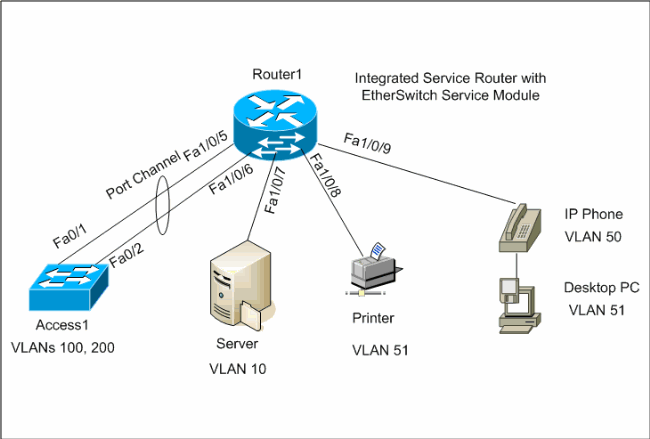
ネットワーク図
このドキュメントでは、次のネットワーク構成を使用しています。

設定
このドキュメントでは、次の設定を使用します。
EtherSwitch モジュールの初期設定
ES モジュールをルータに取り付けた後、新しい GigabitEthernet interface x/0(x はスロット番号)が IOS により認識されていることが確認できます。 次の出力は、ES モジュールをルータに取り付けた後に取得されたものです。
Router1#show ip interface brief
Interface                  IP-Address      OK? Method Status                Protocol

GigabitEthernet0/0         1.1.1.3         YES NVRAM  up                    down

GigabitEthernet0/1         unassigned      YES NVRAM  administratively down down

GigabitEthernet1/0         unassigned      YES unset  administratively down down

Vlan1                      unassigned      YES NVRAM  up                    up
service-module gigabitEthernet x/0 session コマンドは特権 EXEC モード コマンドで、ホスト ルータから ES モジュールにコンソール接続するために使用します。 ES モジュールを設定するためには、ES モジュールにコンソール接続する必要があります。 ES モジュールにコンソール接続するためには、GigabitEthernet interface x/0 の IP アドレスを設定する必要があります。 IP アドレスを割り当てずにモジュールにコンソール接続しようとすると、次のエラー メッセージが表示されます。
Router1#service-module gigabitEthernet 1/0 session
IP address needs to be configured on interface GigabitEthernet1/0
| Router1 |
|---|
Find out the router interface connected to the ES module.

Router1#show cdp neighbors
Capability Codes: R - Router, T - Trans Bridge, B - Source Route Bridge
                  S - Switch, H - Host, I - IGMP, r - Repeater, P - Phone

Device ID    Local Intrfce   Holdtme    Capability   Platform    Port ID
Lab-2811     Gi 1/0          157               R     NME-16ES-1G Gi 1/0/2


!--- The Local interface shows the interface !--- on the router connected internally to the switch.


Configure the host router to manage the ES module.


Router1#configure terminal
Enter configuration commands, one per line.  End with CNTL/Z.
Router1(config)#interface gigabitethernet 1/0

Router1(config-if)#ip address 172.16.1.1 255.255.255.0
Router1(config-if)#no shutdown
Router1(config-if)#exit
Router1(config)#exit


Console into the ES Module


Router1#service-module gigabitEthernet 1/0 session
Trying 172.16.1.1, 2066 ... Open

         --- System Configuration Dialog ---

Would you like to enter the initial configuration dialog? [yes/no]: no

Would you like to terminate autoinstall? [yes]:
Switch>enable
Switch#configure terminal
Enter configuration commands, one per line.  End with CNTL/Z.
Switch(config)#hostname Switch-ES
Switch-ES(config)#interface gigabitethernet 1/0/2

Switch-ES(config-if)#no switchport
Switch-ES(config-if)#ip address 172.16.1.2 255.255.255.0
Switch-ES(config-if)#exit

!--- GigabitEthernet 1/0/2 connects the ES module to the router.


Switch-ES(config)#line console 0
Switch-ES(config-line)#password a99l3
Switch-ES(config-line)#exec-timeout 30
Switch-ES(config-line)#exit
Switch-ES(config)#line vty 0 4
Switch-ES(config-line)#password a99l3
Switch-ES(config-line)#login
Switch-ES(config-line)#exec-timeout 30
Switch-ES(config-line)#exit
|
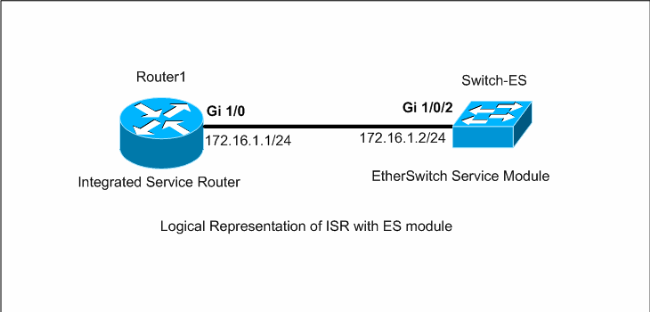
この出力には、ES モジュールからの show ip interface brief コマンドが示されています。 GigabitEthernet1/0/2 インターフェイスは、ES モジュールをホスト ルータの GigabitEthernet1/0 インターフェイスに接続します。
Switch-ES#show ip int brief
Interface              IP-Address      OK? Method Status                Protocol
Vlan1                  unassigned      YES unset  administratively down down
FastEthernet1/0/1      unassigned      YES unset  down                  down
FastEthernet1/0/2      unassigned      YES unset  down                  down
FastEthernet1/0/3      unassigned      YES unset  down                  down
FastEthernet1/0/4      unassigned      YES unset  down                  down
FastEthernet1/0/5      unassigned      YES unset  down                  down
FastEthernet1/0/6      unassigned      YES unset  down                  down
FastEthernet1/0/7      unassigned      YES unset  down                  down
FastEthernet1/0/8      unassigned      YES unset  down                  down
FastEthernet1/0/9      unassigned      YES unset  down                  down
FastEthernet1/0/10     unassigned      YES unset  down                  down
FastEthernet1/0/11     unassigned      YES unset  down                  down
FastEthernet1/0/12     unassigned      YES unset  down                  down
FastEthernet1/0/13     unassigned      YES unset  down                  down
FastEthernet1/0/14     unassigned      YES unset  down                  down
FastEthernet1/0/15     unassigned      YES unset  down                  down
FastEthernet1/0/16     unassigned      YES unset  down                  down
GigabitEthernet1/0/1   unassigned      YES unset  down                  down
GigabitEthernet1/0/2   172.16.1.2      YES manual  up                    up
ES モジュール、または ES モジュールに接続されているデバイスがホスト ルータを介して外部ネットワークと通信する必要がある場合、このポート(GigabitEthernet1/0/2)はレイヤ 3 ポートであるか、レイヤ 3 VLAN のメンバである必要があります。 ES モジュールでのルーティングの設定方法については、このドキュメントの「ルーティングの設定」のセクションを参照してください。
次の図で、ホスト ルータと ES モジュールの論理接続を説明します。

ホスト ルータに戻るには、Ctrl+Shift+6 を押してから X を押す必要があります。
ルータからセッションをクリアする必要がある場合は、ルータの特権 EXEC モードから service-module gigabitEthernet x/0 session clear コマンドを発行します。
VTP と VLAN の設定
デフォルトでは、ES モジュールでの VTP モードはサーバで、VTP ドメイン名は null です。 デフォルトでは、すべてのポートが vlan1 に属します。 この例では、DHCP サーバ(172.16.10.20)が vlan 10 に位置しています。 DHCP サーバからこれらの VLAN に位置しているデバイスの IP アドレスを取得するため、vlan 10 を除くすべての VLAN 上で ip helper-address 172.16.10.20 コマンドが設定されています。
| Switch-ES |
|---|
VTP Configuration Switch-ES(config)#vtp mode transparent Setting device to VTP TRANSPARENT mode. Switch-ES(config)#vtp domain LAB Changing VTP domain name from NULL to LAB Switch-ES(config)# Create VLANs Switch-ES(config)#vlan 10,50,51,100,200 Switch-ES(config-vlan)#exit Switch-ES(config)# Configure VLANs Switch-ES(config)#interface vlan 10 Switch-ES(config-if)#ip address 172.16.10.1 255.255.255.0 Switch-ES(config-if)#no shutdown Switch-ES(config-if)#interface vlan 50 Switch-ES(config-if)#ip address 172.16.50.1 255.255.255.0 Switch-ES(config-if)#ip helper-address 172.16.10.20 Switch-ES(config-if)#no shutdown Switch-ES(config-if)#interface vlan 51 Switch-ES(config-if)#ip address 172.16.51.1 255.255.255.0 Switch-ES(config-if)#ip helper-address 172.16.10.20 Switch-ES(config-if)#no shutdown Switch-ES(config-if)#interface vlan 100 Switch-ES(config-if)#ip address 172.16.100.1 255.255.255.0 Switch-ES(config-if)#ip helper-address 172.16.10.20 Switch-ES(config-if)#no shutdown Switch-ES(config-if)#interface vlan 200 Switch-ES(config-if)#ip address 172.16.200.1 255.255.255.0 Switch-ES(config-if)#ip helper-address 172.16.10.20 Switch-ES(config-if)#no shutdown |
Switch-ES#show vlan

VLAN Name                             Status    Ports
---- -------------------------------- --------- -------------------------------
1    default                          active    Fa1/0/1, Fa1/0/2, Fa1/0/3
                                                Fa1/0/4, Fa1/0/7, Fa1/0/8
                                                Fa1/0/9, Fa1/0/10, Fa1/0/11
                                                Fa1/0/12, Fa1/0/13, Fa1/0/14
                                                Fa1/0/15, Fa1/0/16, Gi1/0/1
                                                Gi1/0/2
10   VLAN0010                         active
50   VLAN0050                         active
51   VLAN0051                         active
100  VLAN0100                         active

200  VLAN0200                         active
1002 fddi-default                     act/unsup
1003 token-ring-default               act/unsup
1004 fddinet-default                  act/unsup
1005 trnet-default                    act/unsup

VLAN Type  SAID       MTU   Parent RingNo BridgeNo Stp  BrdgMode Trans1 Trans2
---- ----- ---------- ----- ------ ------ -------- ---- -------- ------ ------
1    enet  100001     1500  -      -      -        -    -        0      0

VLAN Type  SAID       MTU   Parent RingNo BridgeNo Stp  BrdgMode Trans1 Trans2
---- ----- ---------- ----- ------ ------ -------- ---- -------- ------ ------
10   enet  100010     1500  -      -      -        -    -        0      0
50   enet  100050     1500  -      -      -        -    -        0      0
51   enet  100051     1500  -      -      -        -    -        0      0
100  enet  100100     1500  -      -      -        -    -        0      0

200  enet  100200     1500  -      -      -        -    -        0      0
1002 fddi  101002     1500  -      -      -        -    -        0      0
1003 tr    101003     1500  -      -      -        -    -        0      0
1004 fdnet 101004     1500  -      -      -        ieee -        0      0
1005 trnet 101005     1500  -      -      -        ibm  -        0      0

Remote SPAN VLANs
------------------------------------------------------------------------------


Primary Secondary Type              Ports
------- --------- ----------------- ------------------------------------------
Switch-ES#show vtp status
VTP Version                     : 2
Configuration Revision          : 0
Maximum VLANs supported locally : 1005
Number of existing VLANs        : 10
VTP Operating Mode              : Transparent
VTP Domain Name                 : LAB
VTP Pruning Mode                : Disabled
VTP V2 Mode                     : Disabled
VTP Traps Generation            : Disabled
MD5 digest                      : 0x21 0x51 0xD5 0x4E 0x30 0xA5 0x46 0x3C
Configuration last modified by 0.0.0.0 at 10-27-06 18:28:10
スパニングツリー、トランク、およびポート チャネルの設定
このセクションでは、ES モジュールと Access1 スイッチでのスパニングツリーの設定を示します。 また、ES モジュールと Access1 スイッチの間のポート チャネルとトランクの設定も示します。 次の例では、すべてのスイッチ上で高速スパニングツリーを設定しています。 ES モジュールは、すべての VLAN のスパニングツリーのルートとして設定されます。
| Switch-ES |
|---|
Spanning-Tree Configuration Switch-ES(config)#spanning-tree mode rapid-pvst Switch-ES(config)#spanning-tree vlan 10,50,51,100,200 root primary Trunk & Port Channel Configuration Switch-ES(config)#interface port-channel 1 Switch-ES(config-if)#switchport trunk encapsulation dot1q Switch-ES(config-if)#switchport mode trunk Switch-ES(config-if)#switchport trunk allowed vlan 100,200 Switch-ES(config-if)#exit Switch-ES(config)#interface range fastethernet 1/0/5-6 Switch-ES(config-if-range)#switchport trunk encapsulation dot1q Switch-ES(config-if-range)#switchport mode trunk Switch-ES(config-if-range)#switchport trunk allowed vlan 100,200 Switch-ES(config-if-range)#channel-group 1 mode on Switch-ES(config-if-range)#exit |
| Access1 |
|---|
Access1 switch configuration Access1(config)#vtp mode transparent Setting device to VTP TRANSPARENT mode. Access1(config)#vtp domain LAB Changing VTP domain name from NULL to LAB Access1(config)#vlan 100,200 Access1(config-vlan)#exit Access1(config)#spanning-tree mode rapid-pvst Access1(config)#interface port-channel 1 Access1(config-if)#switchport trunk encapsulation dot1q Access1(config-if)#switchport mode trunk Access1(config-if)#switchport trunk allowed vlan 100,200 Access1(config-if)#exit Access1(config)#interface range FastEthernet 0/1 - 2 Access1(config-if-range)#switchport trunk encapsulation dot1q Access1(config-if-range)#switchport mode trunk Access1(config-if-range)#switchport trunk allowed vlan 100,200 Access1(config-if-range)#channel-group 1 mode on Access1(config-if-range)#exit |
Switch-ES#show spanning-tree summary
Switch is in rapid-pvst mode
Root bridge for: VLAN0001, VLAN0100, VLAN0200
Extended system ID           is enabled
Portfast Default             is disabled
PortFast BPDU Guard Default  is disabled
Portfast BPDU Filter Default is disabled
Loopguard Default            is disabled
EtherChannel misconfig guard is enabled
UplinkFast                   is disabled
BackboneFast                 is disabled
Configured Pathcost method used is short

Name                   Blocking Listening Learning Forwarding STP Active
---------------------- -------- --------- -------- ---------- ----------
VLAN0001                     0         0        0          1          1
VLAN0100                     0         0        0          1          1
VLAN0200                     0         0        0          1          1
---------------------- -------- --------- -------- ---------- ----------
3 vlans                      0         0        0          3          3
Switch-ES#show interface port-channel 1 trunk

Port        Mode         Encapsulation  Status        Native vlan
Po1         on           802.1q         trunking      1

Port      Vlans allowed on trunk
Po1         100,200

Port        Vlans allowed and active in management domain
Po1         100,200

Port        Vlans in spanning tree forwarding state and not pruned
Po1         100,200
アクセス ポートの設定
アクセス ポートの設定は、標準的な LAN スイッチ設定に似ています。
| Switch-ES |
|---|
Configure the port for server Switch-ES(config)#interface fastEthernet 1/0/7 Switch-ES(config-if)#switchport mode access Switch-ES(config-if)#switchport access vlan 10 Switch-ES(config-if)#spanning-tree portfast Switch-ES(config-if)#speed 100 Switch-ES(config-if)#duplex full Switch-ES(config-if)#exit Configure Port for Printer Switch-ES(config)#interface fastethernet 1/0/8 Switch-ES(config-if)#switchport mode access Switch-ES(config-if)#switchport access vlan 51 Switch-ES(config-if)#spanning-tree portfast Switch-ES(config-if)#exit |
音声ポートの設定
音声ポートの設定は、標準的な LAN スイッチ設定に似ています。
| Switch-ES |
|---|
Configure the port for Voice Switch-ES(config)#interface fastethernet 1/0/9 Switch-ES(config-if)#switchport mode access Switch-ES(config-if)#switchport access vlan 51 Switch-ES(config-if)#switchport voice vlan 50 Switch-ES(config-if)#spanning-tree portfast |
ルーティングの設定
この例ではスタティック ルートを使用してルーティングを設定します。
| Switch-ES |
|---|
Configure the default route Switch-ES(config)#ip routing Switch-ES(config)#ip route 0.0.0.0 0.0.0.0 172.16.1.1 |
| Router1 |
|---|
Configure the route to LAN Router1(config)#ip route 172.16.0.0 255.255.0.0 172.16.1.2 |
QoS の設定
このセクションでは自動 QoS を使用して QoS を設定します。 自動 QoS の詳細については、『Cisco AutoQoS White Paper』を参照してください。
| Switch-ES |
|---|
Configure QoS on the port where IP phone is connected Switch-ES(config)#interface fastethernet 1/0/9 Switch-ES(config-if)#auto qos voip cisco-phone Switch-ES(config-if)#exit Configure QoS on the uplink port to the host router. Switch-ES(config)#interface gigabitEthernet 1/0/2 Switch-ES(config-if)#auto qos voip trust |
| Router1 |
|---|
Create Class map Router1(config)#class-map match-any VoIP-Control Router1(config-cmap)#match ip dscp AF31 Router1(config-cmap)#exit Router1(config)#class-map match-any VoIP-RTP Router1(config-cmap)#match ip dscp EF Router1(config-cmap)#exit Create Policy map Router1(config)#policy-map Policy-VoIP Router1(config-pmap)#class VoIP-RTP Router1(config-pmap-c)#priority percent 70 Router1(config-pmap-c)#class VoIP-Control Router1(config-pmap-c)#bandwidth percent 5 Router1(config-pmap-c)#class class-default Router1(config-pmap-c)#fair-queue Router1(config-pmap-c)#exit Router1(config-pmap)#exit Apply the policy on the interface connects to the ES Module Router1(config)#interface gigabitEthernet 1/0 Router1(config-if)#service-policy output Policy-VoIP Router1(config-if)#exit |
確認
現在、この設定に使用できる確認手順はありません。
トラブルシューティング
現在のところ、この設定に関する特定のトラブルシューティング情報はありません。
 フィードバック