ケーブルを介した GRE トンネルの設定
概要
この文書は、ケーブル環境における Generic Routing Encapsulation(GRE; 総称ルーティング カプセル化)の説明、設定、および検証について記載しています。 GRE はシスコによって開発されたトンネリング プロトコルで、IP トンネルの内部にさまざまなプロトコル パケット タイプをカプセル化できます。
はじめに
表記法
ドキュメント表記の詳細は、『シスコ テクニカル ティップスの表記法』を参照してください。
前提条件
このドキュメントに関する固有の要件はありません。
使用するコンポーネント
このドキュメントの情報は、次のソフトウェアとハードウェアのバージョンに基づくものです。
-
Cisco IOS® ソフトウェア リリース 12.1(5)T4 を実行するケーブルモデム uBR924
注: 異なる Cisco IOSバージョンを使用して uBR904 ののような他の Ciscoケーブルモデム プラットフォームの GREトンネルを、設定することは可能性のあるであるがこの機能のための公式サポートは on Cisco uBR920 のためのおよび uBR910 のための Cisco IOS 12.1(3)からの IOS 12.1(5)T4 です。
| ケーブルモデムプラットフォーム | Cisco IOS ソフトウェア リリース |
|---|---|
| ubr920 | 12.1(5)T4 |
| uBR910 | 12.1(3) およびそれ以降から |
この設定を実行するには、2 つのケーブル モデル間に IP 接続を確立する必要があります。
このドキュメントの情報は、特定のラボ環境にあるデバイスに基づいて作成されたものです。 このドキュメントで使用するすべてのデバイスは、クリアな(デフォルト)設定で作業を開始しています。 対象のネットワークが実稼働中である場合には、どのような作業についても、その潜在的な影響について確実に理解しておく必要があります。
背景理論
トンネリングは、トランスポート プロトコルの内部で異種プロトコルのパケットをカプセル化する方法を提供します。 トンネリングは単純なインターフェイスで設定できるように、仮想インターフェイスとして実装されています。 トンネル インターフェイスは特定の「パッセンジャー」または「トランスポート」プロトコルに 関連づけられておらず、むしろ標準のポイントツーポイント カプセル化方式の実装に必要なサービスを提供するためのアーキテクチャといえます。 トンネルはポイントツーポイント リンクであるため、リンクごとに個別にトンネルを設定する必要があります。
GRE はシスコによって開発されたトンネリング プロトコルで、IP トンネルの内部にさまざまなプロトコル パケット タイプをカプセル化し、リモート ポイントにある Cisco ルータに対して IP インターネットワークを越えた仮想的なポイントツーポイント リンクを確立できます。 GRE を使用した IP トンネリングでは、マルチプロトコル サブネットワークをシングル プロトコルのバックボーン環境に接続することで、シングル プロトコル バックボーン環境全体にわたってネットワークを拡張できます。 Cable Modem Termination System(CMTS; ケーブル モデム終端システム)は Data-over-Cable Service Interface Specifications(DOCSIS)に準拠したヘッドエンド ケーブル ルータで、Cisco uBR7246、uBR7223、uBR7246VXR などがこれに該当します。
設定
この項では、このドキュメントで説明する機能の設定に必要な情報を提供します。
ネットワーク図
このドキュメントでは次の図に示すネットワーク構成を使用しています。
このセットアップでは、2 台のケーブル モデム、uBR924-ddd5 と uBR924-b5db の間にトンネルが作成されます。 次の例は 2 台の uBR924 と 1 台の uBR7246VXR を使用しています。 ケーブル モデムの名前は ubr924-ddd5 と ubr924-b5db で、どちらも Cisco IOS バージョン 12.1(5)T4 を使用しています。 トンネル インターフェイスは、コマンド interface tunnel 0 を入力することにより、グローバル設定モードで動的に作成されます。
注: uBR900 ケーブル モデムは、2 つのケーブル モデム間での IP 接続が確立されている限り、同じ uBR7200 CMTS または同じサービス プロバイダーのネットワークに接続する必要はありません。

設定
このドキュメントでは次に示す設定を使用しています。
注: 太字のテキストは GRE 関連のコマンドを表しています。<TT> !-- 青で示されているのは、上の行に関するコメントです。
| ubr924-ddd5 |
|---|
version 12.1 no service single-slot-reload-enable no service pad service timestamps debug uptime service timestamps log uptime no service password-encryption ! hostname ubr924-ddd5 ! logging rate-limit console 10 except errors ! clock timezone - -80 ip subnet-zero no ip finger ! call rsvp-sync ! ! ! ! ! ! ! ! ! ! interface Tunnel0 !--- Tunnel interface 0. ip address 192.168.20.1 255.255.255.0 !--- IP address of the GRE tunnel interface 0. tunnel source Ethernet0 !--- IP source of the tunnel. It is best to make this an !--- interface with a public, routable IP address so that !--- it is reachable from the other endpoint of the tunnel. tunnel destination 11.11.11.11 !--- IP destination of the tunnel. Make sure this is !--- reachable via the ping command !--- Otherwise, the tunnel will not be created properly. ! interface Ethernet0 ip address 9.9.9.9 255.255.255.0 ip rip send version 2 !--- Send RIP version 2 packets. ip rip receive version 2 !--- Receive RIP version 2 packets. ! interface cable-modem0 ip rip send version 2 !--- Send RIP version 2 packets. ip rip receive version 2 !--- Receive RIP version 2 packets. cable-modem downstream saved channel 525000000 40 1 cable-modem mac-timer t2 40000 no cable-modem compliant bridge ! router rip version 2 passive-interface Tunnel0 !--- This command is used to avoid recursive routing. network 10.0.0.0 network 9.0.0.0 no auto-summary ! ip default-gateway 10.1.4.1 ip classless no ip http server no ip http cable-monitor ! snmp-server packetsize 4096 snmp-server manager ! voice-port 0 input gain -2 ! voice-port 1 input gain -2 ! ! line con 0 transport input none line vty 0 4 login ! end ubr924-ddd5# |
| ubr924-b5db |
|---|
version 12.1 no service single-slot-reload-enable no service pad service timestamps debug uptime service timestamps log uptime no service password-encryption ! hostname ubr924-b5db ! logging rate-limit console 10 except errors enable password ww ! clock timezone - -80 ip subnet-zero no ip finger ! mgcp call rsvp-sync ! ! ! ! ! ! ! ! ! ! interface Tunnel0 !--- Tunnel interface 0 ip address 192.168.20.2 255.255.255.0 !--- IP address of the gre tunnel interface 0 tunnel source Ethernet0 !--- IP source of the tunnel. It is best to make this an !--- interface with a public, routable IP address so that !--- it is reachable from the other endpoint of the tunnel. tunnel destination 9.9.9.9 !--- IP destination of the tunnel. Make sure this is !--- reachable via the ping command !--- Otherwise, the tunnel will not be created properly. ! interface Ethernet0 ip address 11.11.11.11 255.255.255.0 ip rip send version 2 !--- Send RIP version 2 packets. ip rip receive version 2 !--- Receive RIP version 2 packets. ! no ip route-cache no ip mroute-cache ! interface cable-modem0 ip rip send version 2 !--- Send RIP version 2 packets. ip rip receive version 2 !--- Receive RIP version 2 packets. no ip route-cache no ip mroute-cache no cable-modem compliant bridge ! router rip version 2 passive-interface Tunnel0 !--- This command is used to avoid recursive routing. network 10.0.0.0 network 11.0.0.0 no auto-summary ! ip default-gateway 10.1.4.1 ip classless no ip http server no ip http cable-monitor ! snmp-server packetsize 4096 snmp-server manager ! voice-port 0 input gain -2 ! voice-port 1 input gain -2 ! ! line con 0 exec-timeout 0 0 transport input none line vty 0 4 password ww login ! end ubr924-b5db# |
確認
このセクションでは、設定が正常に動作しているかどうかを確認する際に役立つ情報を提供しています。
特定の show コマンドは、アウトプット インタープリタでサポートされています。このツールを使用すると、show コマンド出力を分析できます。
最初に、CMTS(7246VXR)の設定に誤りがないこと、およびケーブル モデムがオンラインになっていることを確認します。 次に CMTS の設定を示します。
7246VXR#show run
Building configuration...

Current configuration : 4579 bytes
!
! Last configuration change at 13:22:17 PDT Mon Feb 26 2001
! NVRAM config last updated at 13:22:46 PDT Mon Feb 26 2001
!
version 12.1
no service single-slot-reload-enable
no service pad
service timestamps debug datetime msec localtime
service timestamps log datetime localtime
no service password-encryption
service linenumber
service udp-small-servers max-servers no-limit
!
hostname 7246VXR
!
logging buffered 1000000 debugging
logging rate-limit console 10 except errors
enable password cable
!
cable qos profile 8
cable qos profile 10
cable qos profile 10 grant-size 1500
cable qos profile 12 guaranteed-upstream 100000
no cable qos permission create
no cable qos permission update
cable qos permission modems
cable time-server
clock timezone PDT -8
clock summer-time PDT recurring
clock calendar-valid
ip subnet-zero
no ip finger
!
interface Ethernet2/0
 ip address 172.16.30.4 255.255.255.192
 no ip mroute-cache
 half-duplex
!

interface Cable4/0
 ip address 172.16.29.1 255.255.255.224 secondary
 ip address 10.1.4.1 255.255.255.0
 no keepalive
 cable downstream rate-limit token-bucket shaping
 cable downstream annex B
 cable downstream modulation 64qam
 cable downstream interleave-depth 32
 cable downstream frequency 555000000
 cable upstream 0 frequency 40000000
 cable upstream 0 power-level 0
 no cable upstream 0 shutdown
 cable upstream 1 shutdown
 cable upstream 2 shutdown
 cable upstream 3 shutdown
 cable upstream 4 shutdown
 cable upstream 5 shutdown
 cable dhcp-giaddr policy
 cable helper-address 172.16.30.2
!
interface Cable5/0
 ip address 172.16.29.225 255.255.255.224 secondary
 ip address 10.1.5.1 255.255.255.0
 load-interval 30
 no keepalive
 cable downstream rate-limit token-bucket shaping
 cable downstream annex B
 cable downstream modulation 64qam
 cable downstream interleave-depth 32
 cable downstream frequency 620000000
 cable upstream 0 frequency 25008000
 cable upstream 0 power-level 0
 no cable upstream 0 shutdown
 no cable upstream 1 shutdown
 cable dhcp-giaddr policy
!
router eigrp 202
 redistribute connected
 redistribute static
 network 10.0.0.0
 network 172.16.0.0
 no auto-summary
 no eigrp log-neighbor-changes
!
router rip
 version 2
 redistribute connected
 redistribute static
 network 10.0.0.0
 network 172.16.0.0
 no auto-summary
!
ip default-gateway 172.16.30.1
ip classless
ip route 0.0.0.0 0.0.0.0 172.16.30.1
ip route 172.16.30.0 255.255.255.0 Ethernet2/0
ip http server
ip http authentication local
!
access-list 188 permit tcp any any eq www log
access-list 188 permit ip any any
route-map docsis permit 10
!
snmp-server engineID local 00000009020000E01ED77E40
snmp-server community public RO
snmp-server community private RW

line con 0
 exec-timeout 0 0
 transport input none
line aux 0
 speed 19200
line vty 0 4
 session-timeout 60
 exec-timeout 0 0
!
ntp clock-period 17179973
end

7246VXR#show cable modem
Interface   Prim Online     Timing Rec    QoS CPE IP address      MAC address
            Sid  State      Offset Power
Cable4/0/U0 69   online     2812    0.25  5   0   10.1.4.3        0002.1685.b5db
Cable4/0/U0 70   online     2288    0.00  5   0   10.1.4.6        0010.7bed.9b23
Cable4/0/U0 71   online     2289    0.50  5   0   10.1.4.2        0010.7bed.9b45
Cable4/0/U0 72   online     2812    0.00  5   0   10.1.4.4        0002.fdfa.0a63
Cable4/0/U0 73   online     2812   -0.75  5   0   10.1.4.5        0004.2752.ddd5
Cable4/0/U0 74   online     2813    0.25  5   0   10.1.4.7        0001.64ff.e47d
ケーブルモデム オンライン状態がオンラインを示さない場合、Troubleshooting UBR Cable Modems Not Coming Online の ドキュメントを参照して下さい。
7246VXR#show ip interface brief
Interface                  IP-Address      OK? Method Status                Protocol
FastEthernet0/0            192.168.7.253   YES NVRAM  up                    down
Ethernet2/0                172.16.30.4     YES manual up                    up
Ethernet2/1                unassigned      YES NVRAM  administratively down down
Ethernet2/2                unassigned      YES NVRAM  administratively down down
Ethernet2/3                unassigned      YES NVRAM  administratively down down
Cable3/0                   10.1.3.1        YES manual up                    up
Cable4/0                   10.1.4.1        YES manual up                    up
Cable5/0                   10.1.5.1        YES manual up                    up

7246VXR#show ip route
Codes: C - connected, S - static, I - IGRP, R - RIP, M - mobile, B - BGP
       D - EIGRP, EX - EIGRP external, O - OSPF, IA - OSPF inter area
       N1 - OSPF NSSA external type 1, N2 - OSPF NSSA external type 2
       E1 - OSPF external type 1, E2 - OSPF external type 2, E - EGP
       i - IS-IS, L1 - IS-IS level-1, L2 - IS-IS level-2, ia - IS-IS inter area
       * - candidate default, U - per-user static route, o - ODR
       P - periodic downloaded static route

Gateway of last resort is 172.16.30.1 to network 0.0.0.0

     172.16.0.0/16 is variably subnetted, 4 subnets, 3 masks
C       172.16.29.224/27 is directly connected, Cable5/0
C       172.16.29.0/27 is directly connected, Cable4/0
S       172.16.30.0/24 is directly connected, Ethernet2/0
C       172.16.30.0/26 is directly connected, Ethernet2/0
     9.0.0.0/24 is subnetted, 1 subnets
R       9.9.9.0 [120/1] via 10.1.4.5, 00:00:09, Cable4/0
R    192.168.20.0/24 [120/1] via 10.1.4.5, 00:00:09, Cable4/0
     10.0.0.0/8 is variably subnetted, 5 subnets, 2 masks
C       10.1.3.0/24 is directly connected, Cable3/0
R       10.5.5.0/24 [120/1] via 10.1.4.4, 00:00:01, Cable4/0
R       10.0.0.0/8 [120/1] via 172.16.30.10, 00:00:24, Ethernet2/0
C       10.1.5.0/24 is directly connected, Cable5/0
C       10.1.4.0/24 is directly connected, Cable4/0
     11.0.0.0/24 is subnetted, 1 subnets
R       11.11.11.0 [120/1] via 10.1.4.3, 00:00:15, Cable4/0
S*   0.0.0.0/0 is directly connected
ここで、両方のケーブル モデムで sh version の 出力を確認します。
ubr924-ddd5#sh ver
Cisco Internetwork Operating System Software
IOS (tm) 920 Software (UBR920-K1V4Y556I-M), Version 12.1(5)T4,  RELEASE SOFTWARE (fc1)
TAC Support: http://www.cisco.com/pcgi-bin/ibld/view.pl?i=support
Copyright (c) 1986-2001 by cisco Systems, Inc.
Compiled Fri 02-Feb-01 10:55 by ccai
Image text-base: 0x800100A0, data-base: 0x806DB770

ROM: System Bootstrap, Version 12.0(6r)T3, RELEASE SOFTWARE (fc1)
ROM: 920 Software (UBR920-K1V4Y556I-M), Version 12.1(5)T4,  RELEASE SOFTWARE (fc1)

ubr924-ddd5 uptime is 2 hours, 1 minute
System returned to ROM by reload at 12:45:25 - Fri Feb 23 2001
System restarted at 12:46:07 - Fri Feb 23 2001
System image file is "flash:ubr920-k1v4y556i-mz.121-5.T4"

cisco uBR920 CM (MPC850) processor (revision 4.d) with 15872K/1024K bytes of memory.
Processor board ID FAA0444Q14Z
Bridging software.
1 Ethernet/IEEE 802.3 interface(s)
1 Cable Modem network interface(s)
3968K bytes of processor board System flash (Read/Write)
1536K bytes of processor board Boot flash (Read/Write)

Configuration register is 0x2102

ubr924-b5db#show ver
Cisco Internetwork Operating System Software
IOS (tm) 920 Software (UBR920-K1V4Y556I-M), Version 12.1(5)T4,  RELEASE SOFTWARE (fc1)
TAC Support: http://www.cisco.com/pcgi-bin/ibld/view.pl?i=support
Copyright (c) 1986-2001 by cisco Systems, Inc.
Compiled Fri 02-Feb-01 10:55 by ccai
Image text-base: 0x800100A0, data-base: 0x806DB770

ROM: System Bootstrap, Version 12.0(6r)T3, RELEASE SOFTWARE (fc1)
ROM: 920 Software (UBR920-K1V4Y556I-M), Version 12.1(5)T4,  RELEASE SOFTWARE (fc1)

ubr924-b5db uptime is 1 hour, 53 minutes
System returned to ROM by reload at 12:55:34 - Fri Feb 23 2001
System restarted at 12:56:15 - Fri Feb 23 2001
System image file is "flash:ubr920-k1v4y556i-mz.121-5.T4"

cisco uBR920 CM (MPC850) processor (revision 3.e) with 15872K/1024K bytes of memory.
Processor board ID FAA0422Q04F
Bridging software.
1 Ethernet/IEEE 802.3 interface(s)
1 Cable Modem network interface(s)
3968K bytes of processor board System flash (Read/Write)
1536K bytes of processor board Boot flash (Read/Write)

Configuration register is 0x2102
次の条件が満たされていれば、トンネルは up/up になります。
-
トンネルに有効な IP アドレスが設定されている。
-
トンネルの宛先 IP アドレス(トンネルの遠端に割り当てられた IP アドレスではない)への経路がルーティング テーブルに存在する。
この条件は宛先アドレスに ping が通るかどうかにかかわらず成立します。 言い換えれば、不適切なスタティック ルートや誤った方向を指し示すデフォルト ルートであってもトンネルはアップしますが、正常に動作しません。
トンネルの動作を検証するための最初のステップは、トンネルがアップしているかどうかを確認することです。 両方のケーブル モデムで show ip interface brief と show interface tunnel 0 を実行します。 次にコマンドの出力例を示します。
ubr924-ddd5#show ip interface brief
Interface                  IP-Address      OK? Method Status                Protocol
Ethernet0                  9.9.9.9         YES manual up                    up
Tunnel0                    192.168.20.1    YES manual up                    up
cable-modem0               10.1.4.5        YES unset  up                    up

ubr924-ddd5#show interface tunnel 0
Tunnel0 is up, line protocol is up
  Hardware is Tunnel
  Internet address is 192.168.20.1/24
  MTU 1514 bytes, BW 9 Kbit, DLY 500000 usec,
     reliability 255/255, txload 1/255, rxload 1/255
  Encapsulation TUNNEL, loopback not set
  Keepalive set (10 sec)
  Tunnel source 9.9.9.9 (Ethernet0), destination 11.11.11.11
  Tunnel protocol/transport GRE/IP, key disabled, sequencing disabled
  Checksumming of packets disabled
  Last input 00:15:25, output 00:14:27, output hang never
  Last clearing of "show interface" counters never
  Queueing strategy: fifo
  Output queue 0/0, 2 drops; input queue 0/75, 0 drops
  5 minute input rate 0 bits/sec, 0 packets/sec
  5 minute output rate 0 bits/sec, 0 packets/sec
     146 packets input, 21024 bytes, 0 no buffer
     Received 0 broadcasts, 0 runts, 0 giants, 0 throttles
     0 input errors, 0 CRC, 0 frame, 0 overrun, 0 ignored, 0 abort
     172 packets output, 57392 bytes, 0 underruns
     0 output errors, 0 collisions, 0 interface resets
     0 output buffer failures, 0 output buffers swapped out


ubr924-b5db#show ip interface brief
Interface                  IP-Address      OK? Method Status                Protocol
Ethernet0                  11.11.11.11     YES manual up                    up
Tunnel0                    192.168.20.2    YES manual up                    up
cable-modem0               10.1.4.3        YES NVRAM  up                    up

ubr924-b5db#show interface tunnel 0
Tunnel0 is up, line protocol is up
  Hardware is Tunnel
  Internet address is 192.168.20.2/24
  MTU 1514 bytes, BW 9 Kbit, DLY 500000 usec,
     reliability 255/255, txload 1/255, rxload 1/255
  Encapsulation TUNNEL, loopback not set
  Keepalive set (10 sec)
  Tunnel source 11.11.11.11 (Ethernet0), destination 9.9.9.9
  Tunnel protocol/transport GRE/IP, key disabled, sequencing disabled
  Checksumming of packets disabled
  Last input 00:16:42, output 00:17:40, output hang never
  Last clearing of "show interface" counters never
  Queueing strategy: fifo
  Output queue 0/0, 5 drops; input queue 0/75, 0 drops
  5 minute input rate 0 bits/sec, 0 packets/sec
  5 minute output rate 0 bits/sec, 0 packets/sec
     118 packets input, 19144 bytes, 0 no buffer
     Received 0 broadcasts, 0 runts, 0 giants, 0 throttles
     0 input errors, 0 CRC, 0 frame, 0 overrun, 0 ignored, 0 abort
     164 packets output, 49624 bytes, 0 underruns
     0 output errors, 0 collisions, 0 interface resets
     0 output buffer failures, 0 output buffers swapped out
トンネルの動作を検証するための次のステップは、トンネルの宛先 IP アドレスに対して ping を実行することです。 これは IP の接続性を検証するだけであり、実際のトンネルの動作は検証されません。
From ubr924-ddd5 we ping 11.11.11.11
ubr924-ddd5#ping 11.11.11.11

Type escape sequence to abort.
Sending 5, 100-byte ICMP Echos to 11.11.11.11, timeout is 2 seconds:
!!!!!
Success rate is 100 percent (5/5), round-trip min/avg/max = 12/14/17 ms
ubr924-ddd5#
ここで、ubr924-b5db から宛先アドレス 9.9.9.9 に対して ping を実行します。
ubr924-b5db#ping 9.9.9.9

Type escape sequence to abort.
Sending 5, 100-byte ICMP Echos to 9.9.9.9, timeout is 2 seconds:
!!!!!
Success rate is 100 percent (5/5), round-trip min/avg/max = 12/14/16 ms
ubr924-b5db#
トンネルの動作を検証するには、show ip route x.x.x.x コマンドを入力します。x.x.x.x は、トンネルの遠端に割り当てられた IP アドレスです。 このケースでは、遠端ルータのループバック アドレスになります。 示される経路がトンネル インターフェイスへの経路だけの場合は、そのアドレスに ping することでトンネルの動作が実証されます。
ネットワークを通じてトンネル セグメントへ経路をアドバタイズし戻す IP アドレッシング方式がある場合、トンネル インターフェイスの遠端への経路は複数存在します。 この場合、トンネルの動作の検証は非常に難しくなります。 一般的 に、トンネル ネットワークへの重複経路は必要ありません。 ルーティング プロトコルがネットワークを越えて経路をアドバタイズしないように、対策を講じることが必要です。 異なるプロトコルのトラフィックを IP から転送するためにトンネルを使用している場合は、基本的に同じ検証方法が適用されます。
From ubr924-ddd5 we get
ubr924-ddd5#show ip route 192.168.20.2
Routing entry for 192.168.20.0/24
  Known via "connected", distance 0, metric 0 (connected, via interface)
  Routing Descriptor Blocks:
  * directly connected, via Tunnel0
      Route metric is 0, traffic share count is 1

From ubr924-b5db we get
ubr924-b5db#show ip route 192.168.20.1
Routing entry for 192.168.20.0/24
  Known via "connected", distance 0, metric 0 (connected, via interface)
  Routing Descriptor Blocks:
  * directly connected, via Tunnel0
      Route metric is 0, traffic share count is 1
PC1 から PC2(およびその逆)にアクセスできることを検証するには、ケーブル モデムで拡張 ping を実行する方法と、PC から ping を実行する方法があります。
最初に、ubr924-b5db のイーサネット インターフェイス(11.11.11.11)から ubr924-ddd5 のイーサネット インターフェイス(9.9.9.9)に対して拡張 ping を実行します。
ubr924-b5db#ping ip
Target IP address: 9.9.9.9

!--- ubr924-ddd5 Ethernet's IP address.

Repeat count [5]:
Datagram size [100]:
Timeout in seconds [2]:
Extended commands [n]: y
Source address or interface: 11.11.11.11

!--- ubr924-b5db Ethernet's IP address.

Type of service [0]:
Set DF bit in IP header? [no]:
Validate reply data? [no]:
Data pattern [0xABCD]:
Loose, Strict, Record, Timestamp, Verbose[none]:
Sweep range of sizes [n]:
Type escape sequence to abort.
Sending 5, 100-byte ICMP Echos to 9.9.9.9, timeout is 2 seconds:
!!!!!
Success rate is 100 percent (5/5), round-trip min/avg/max = 12/16/28 ms
ubr924-b5db#
次に相手側の接続性をテストするため、逆方向に ping を 実行します。
ubr924-ddd5#ping ip
Target IP address: 11.11.11.11

!--- ubr924-b5db Ethernet's IP address.

Repeat count [5]:
Datagram size [100]:
Timeout in seconds [2]:
Extended commands [n]: y
Source address or interface: 9.9.9.9

!--- ubr924-ddd5 Ethernet's IP address.

Type of service [0]:
Set DF bit in IP header? [no]:
Validate reply data? [no]:
Data pattern [0xABCD]:
Loose, Strict, Record, Timestamp, Verbose[none]:
Sweep range of sizes [n]:
Type escape sequence to abort.
Sending 5, 100-byte ICMP Echos to 11.11.11.11, timeout is 2 seconds:
!!!!!
Success rate is 100 percent (5/5), round-trip min/avg/max = 12/14/16 ms
ubr924-ddd5#
最後のテストとして、PC1 から PC2(およびその逆)に対して ping を実行します。
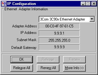
PC1 の IP アドレスは 9.9.9.1 です。

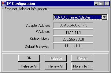
PC2 の IP アドレスは 11.11.11.1 です。

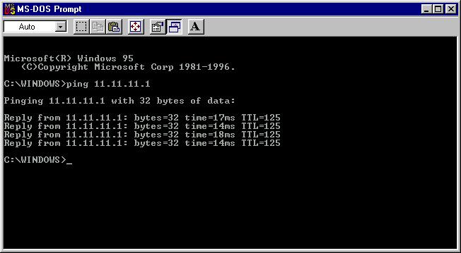
PC1 から PC2 に対して ping を実行すると、次のような結果が得られます。

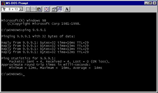
PC2 から PC1 に対して ping を実行しても、同じような結果が得られます。

トラブルシューティング
現在のところ、この設定に関する特定のトラブルシューティング情報はありません。
 フィードバック