New and Changed Information
The following table provides an overview of the significant changes up to this current release. The table does not provide an exhaustive list of all changes or of the new features up to this release.
|
Cisco APIC Release Version |
Feature |
Description |
|---|---|---|
|
5.2(1) |
Support is available for VNet peering across Azure ADs, so spoke VNets can be deployed in different subscriptions in different Azure ADs. |
See Support for VNet Peering Across Azure Active Directories for more information. |
|
5.1(2) |
Azure VNet peering at the global level is enabled by default and cannot be disabled. |
|
|
5.0(2) |
Support for Azure VNET peering in Cisco Cloud APIC |
This release provides support for Azure VNET peering in Cisco Cloud APIC. |
Data Forwarding Between VNets
Prior to Release 5.0(2), the solution for inter-VNet communication in a Cisco Cloud APIC uses a hub-spoke overlay topology with IPsec tunnels between a pair of Cisco CSR routers in the infra VNet and a Virtual Network Gateways (VNG) in the user VNet. BGP runs over the IPsec tunnels as the routing protocol between the CSR routers and the VNG.
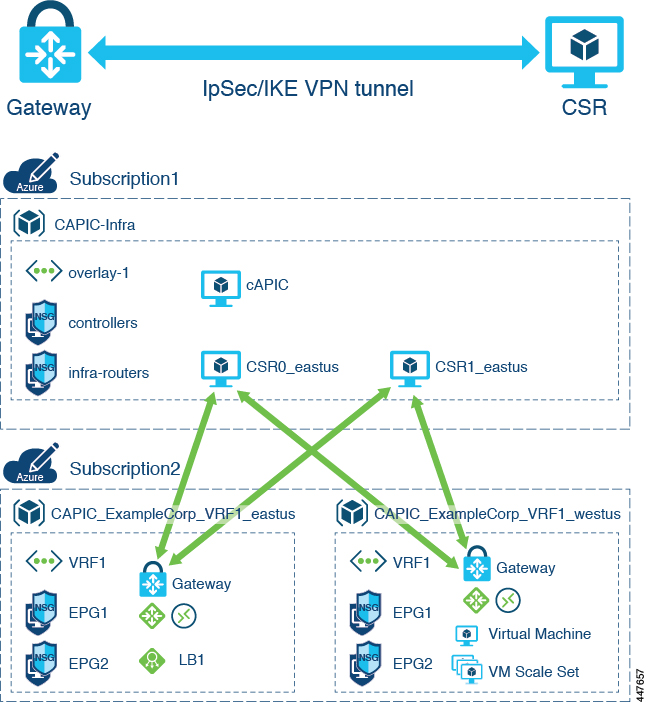
This implementation has several limitations:
-
Azure VPN gateway is an expensive and heavy Azure resource
-
Every user VNet must deploy an Azure VPN gateway in order to forward the traffic to a CSR
-
Each VPN tunnel offers limited bandwidth (1.25 Gbps), which limits the total throughput
-
Creating a virtual network gateway (VPN gateway) can take up to 45 minutes to complete
Beginning in Release 5.0(2), Cisco Cloud APIC supports using Azure VNet peering for inter-VNet connectivity. Azure VNet peering is a service that functions as an internal router to automate connectivity between virtual networks (VNets). The VNets can be in different Azure regions in a cloud site.
VNet peering provides a low-latency, high-bandwidth connection useful in scenarios such as cross-region data replication and database failover. Since traffic is private and remains on the Microsoft backbone, if you have strict data policies, VNet peering becomes preferable because the public internet isn't involved. Since there's no gateway in the path, there are no extra hops, ensuring low-latency connections.
Azure VNet peering, similar to a Cisco CSR, is owned by the infra tenant. However, it’s shared with multiple user accounts.
Cisco APIC Release 5.0(2) is backward-compatible with previous methods of configuring communication between VNets.
About VNet Peering
Virtual network (VNet) peering enables seamless connection between two Azure Virtual Networks and is Microsoft's recommended way of forwarding data between two VNets. The virtual networks appear as one for connectivity purposes. The traffic between virtual machines uses the Microsoft backbone infrastructure. Like traffic between virtual machines in the same network, traffic is routed through Microsoft's private network only. Peerings are bidirectional.
Peering connections are non-transitive. For example, assume three VNets (A, B, and C), where A is bidirectionally peered with B, and B is with C. This does not mean A and C are peered with each other.
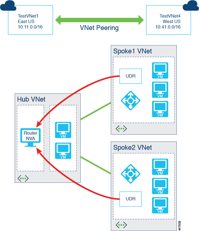
Network traffic between peered virtual networks is private. Traffic between the virtual networks is kept on the Microsoft backbone network. No public Internet, gateways, or encryption is required in the communication between the virtual networks.
The benefits of using virtual network peering include:
-
A low-latency, high-bandwidth connection between resources in different virtual networks.
-
The ability for resources in one virtual network to communicate with resources in a different virtual network.
-
No downtime to resources in either virtual network when creating the peering, or after the peering is created.
-
Much higher traffic throughput compared to IPSec tunnels.
For more information on VNet peering, see the article Virtual network peering in the Documentation section in the Azure website.
Cisco Cloud APIC Implementation of VNet Peering
Cisco Cloud APIC uses several components to implement VNet peering.
Hub and Spoke Topology
Cisco Cloud APIC uses a hub and spoke topology for VNet peering rather than a full-mesh topology because a hub-spoke topology is easier to manage. In the hub-spoke topology, all the user VNets peer with a central hub VNet, forming a full hub and spoke topology.
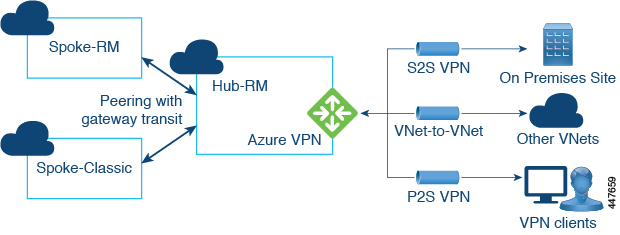
A CSR acts as the network virtual appliance (NVA) in the hub and routes the packets from one VNet to another VNet, and also forms the VXLAN tunnels toward the on-premises site. This kind of connection provides full bandwidth between Azure VNets as supported by your datacenter.
User-Defined Routes
As mentioned previously, peering connections with Azure VNet peering are non-transitive. Since spokes are not peered with each other, Cisco Cloud APIC uses user-defined routes (UDRs) on each user VNet to forward traffic to other VNets.
UDRs are used to override Azure's default system routes, or to add additional routes. UDRs for the spoke are added to a subnet’s route table, with the next-hop pointing to the NLB of the NVA (CSR) in the hub.
Cloud APIC Implementation
The following figure shows how Cloud APIC typically implements VNet peering.
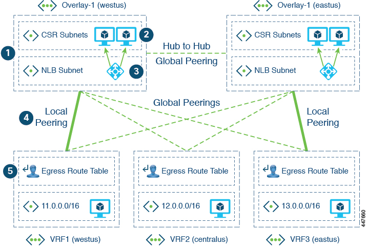
Where:
-
Infra VNets act as the hub, and tenant VNets act as the spokes. Bi-directional peering is used between each hub-spoke pair.
-
CSRs in the hub VNet act as the NVAs for spoke-to-spoke routing.
-
An Azure network load balancer (NLB) is placed in front of the CSRs to perform load-balancing and failover.
-
In a multi-region cloud site on Azure, each region can have its own hub VNet (infra VNet with a pair of CSRs and a NLB), or can share the hub VNet in other regions. All spoke VNets are peered with all hub VNets, across regions. The types of peerings are:
-
Local peering: Peering with hub in the same Azure region
-
Global peering: Peering with hubs in different Azure regions
-
-
The UDR in the spoke VNets redirect traffic to the CSR NLB for traffic destined to other spokes or sites.
For example:
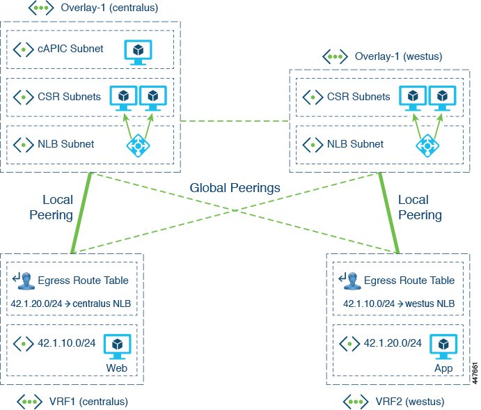
In this example:
-
Spoke-1: VRF1 (42.1.10.0/24)
-
Spoke-2: VRF2 (42.1.20.0/24)
A UDR is needed in each spoke's route table, with one UDR per CIDR in the destination VRF. The next-hop for the UDR is the IP address of the NLB, where the routes with the local NLB are preferred over those with remote NLBs.
In the Cloud APIC implementation of VNet peering:
-
For the hub-to-hub peerings:
-
All of the hub VNets are peered with each other
-
There is bi-directional peering between each pair of hub-hub VNets
-
-
For the hub-to-spoke peerings:
-
The infra VNets act as the hubs
-
The tenant VNets act as the spokes
-
There is bi-directional peering between each pair of hub-spoke VNets
-
-
For the global vs local peerings:
-
A tenant VNet (spoke) is peered with all of the infra VNets (hubs)
-
Local peering: Peering with a hub in the same region
-
Global peering: Peering with a hub in a different region
-
Support for VNet Peering Across Azure Active Directories
With the VNet peering solution available for releases prior to release 5.2(1), there is a limitation in that VNet peering cannot be established between two VNets that belong to different subscriptions corresponding to different Azure Active Directories. Azure Active Directory (Azure AD) is Microsoft’s enterprise cloud-based identity and access management (IAM) solution. An Azure subscription has a trust relationship with Azure AD. A subscription trusts Azure AD to authenticate users, services, and devices.
Multiple subscriptions can trust the same Azure AD, but each subscription can only trust a single Azure AD. One or more Azure subscriptions can establish a trust relationship with an instance of Azure AD in order to authenticate and authorize security principals and devices against Azure services. When a subscription expires, the trusted instance of the Azure AD service remains, but the security principals lose access to Azure resources.
-
In releases prior to release 5.2(1), you must deploy the infra (hub) and spoke VNets in the same Azure AD, but you can deploy the infra and spoke VNets in different subscriptions within the same Azure AD.
-
Beginning with release 5.2(1), support is now available for VNet peering across Azure ADs, so spoke VNets can be deployed in different subscriptions in different Azure ADs.
The following figure shows an example configuration where VNet peering is enabled across Azure ADs.
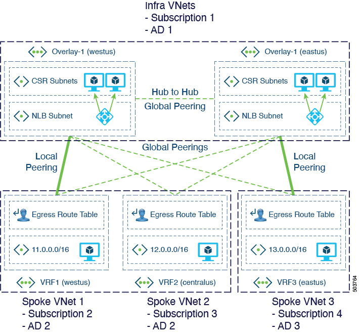
In the example configuration in this figure, each dotted brown box represents a distinct Azure AD boundary, where:
-
Both of the infra VNets belong to Subscription 1, and Subscription 1 belongs to Azure AD 1
-
The spoke VNets belong to these subscriptions and ADs:
-
Spoke VNet 1: Belongs to Subscription 2, and Subscription 2 belongs to Azure AD 2
-
Spoke VNet 2: Belongs to Subscription 3, and Subscription 3 also belongs to Azure AD 2
-
Spoke VNet 3: Belongs to Subscription 4, and Subscription 4 belongs to Azure AD 3
-
-
Local peerings and global peerings behave as they did prior to release 5.2(1), as described in Cisco Cloud APIC Implementation of VNet Peering
If you want to configure VNet peering across Azure ADs, you must make the following configurations:
-
Both the infra tenant and the user tenants must use only the service principal option. VNet peering across Azure ADs can only be achieved by using the service principal mode of authorization on Azure. For more information, see Configuring Infra and User Tenants With Service Principal Mode of Authorization.

Note
The managed identity option is still supported for infra and user tenants if you do not configure VNet peering across Azure ADs.
-
You must make the necessary Contributor role configurations:
-
You must configure the Contributor role on the infra subscription for the service principal associated with the infra tenant.
-
You must configure the Contributor role on the tenant subscription for the service principal associated with the user tenant.
-
-
You must also make the necessary Network Contributor role configurations:
-
You must configure the Network Contributor role on the tenant subscription for the service principal associated with the infra tenant.
-
You must configure the Network Contributor role on the infra subscription for the service principal associated with the user tenant.
-
Following is an example scenario to illustration these configurations. Assume that we have VNet A1, which belongs to the following:
-
Subscription S1
-
Azure active directory 1 (AD 1)
-
Infra tenant
And assume we have VNet B1, which belongs to the following:
-
Subscription S2
-
Azure active directory 2 (AD 2)
-
User tenant
To peer these two VNets, you would need to use service principal for both the infra tenant and the user tenant. For example:
-
The infra tenant uses subscription S1 with access credentials/service principal SP-infra
-
The user tenant uses subscription S2 with access credentials/service principal SP-user
Both of these service principals should have Contributor roles on their respective subscriptions to allow the Cisco Cloud APIC to make the calls to create the VNets and establish the VNet peering, where you would make the following configurations:
-
Assign SP-infra Contributor role on Subscription S1.
-
Assign SP-user Contributor role on Subscription S2.
However, in order to point the peering toward opposite VNets and make the VNet peering connection successful, you also need to make the following configurations:
-
Assign SP-infra Network Contributor role on Subscription S2 for establishing the hub to spoke peering link.
-
Assign SP-user Network Contributor role on Subscription S1 for establishing the spoke to hub peering link.
To make these configurations, you would export SP-infra in AD 1 into AD 2. Similarly, you would also export SP-user in AD 2 into AD 1.
The following link provides an example on exporting service principals across ADs using PowerShell:
How to export Service Principal to different AD
Considerations When Upgrading to Release 5.2(1)
For releases prior to release 5.2(1), the Cisco Cloud APIC virtual machine will have a Contributor role assigned for the subscription for the infra tenant. If you upgrade from a previous release to release 5.2(1) and you want to configure VNet peering across Azure ADs, you will have to make the following manual changes through the Cisco Cloud APIC GUI:
-
Change the Access Type mode to Service Principal for the infra tenant
-
Provide the service principal details for the infra tenant
See Configuring Infra and User Tenants With Service Principal Mode of Authorization for more information.
After you have made those changes, you can remove the Contributor role for the Cisco Cloud APIC virtual machine on the necessary subscriptions in the Azure portal.
Guidelines and Limitations for Azure VNet Peering Across Azure Active Directories
 Note |
The following guidelines and limitations apply specifically for the VNet peering across Azure ADs enhancement available in release 5.2(1). For general guidelines and limitations for Azure VNet peering with Cisco Cloud APIC, see Guidelines and Limitations for Azure VNet Peering. |
With the VNet peering across Azure ADs enhancement available in release 5.2(1), the following guidelines and restrictions apply:
-
The following are allowed when configuring VNet peering across Azure ADs:
-
Infra VNets and spoke VNets can be in different Azure ADs
-
Spokes can be spread across different subscriptions across different Azure ADs
-
-
The following are not allowed when configuring VNet peering across Azure ADs:
-
Infra VNets in a given site cannot be deployed or split across different subscriptions. All infra VNets in a site must belong in the same subscription, which means that all infra VNets in a site must also belong in the same Azure AD.
-
-
The managed identity option is not supported for infra and user tenants when using VNet peering across Azure ADs (service principal must be used instead in this situation).
Configuring Infra and User Tenants With Service Principal Mode of Authorization
These procedures describe how to configure the infra and user tenants with a service principal mode of authorization.
As part of this process, you will create a new App registration of the type multitenant in the active directory, and you will provide the following pieces of information:
-
Subscription ID
-
Application (client) ID
-
Client secret
-
Directory (tentant) ID
At the end of this process, you will run an az command that is provided to you by the service provider.
The procedures for configuring a tenant with a service principal mode of authorization is identical, whether that tenant is an infra tenant or a user tenant, with the exception of the point where you will set the service principal mode of authorization for the infra tenant or user tenant in the Cisco Cloud APIC GUI, where:
-
For the infra tenant, you will be editing an existing infra tenant to set the service principal mode of authorization for that tenant
-
For the user tenant, you can create a new user tenant or edit an existing user tenant to set the service principal mode of authorization for that tenant
These procedures are therefore provided in the following fashion:
-
Follow the procedures provided in this section to first configure the infra tenant a service principal mode of authorization in Azure.
-
Once you have completed these procedures to configure the infra tenant, return to the beginning and follow all of these procedures a second time, this time to configure the user tenant with a service principal mode of authorization in Azure.
Keep in mind that you will have to make additional tenant-specific configurations to configure the Network Contributor role for both the infra and user tenant subscriptions.
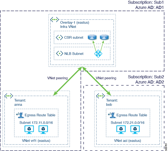
These procedures will use the following topology example.
Procedure
| Step 1 |
Log into the appropriate Azure account for the Cloud APIC infra or user tenant and go to the Azure management portal, if you are not there already: https://portal.azure.com/#home
|
| Step 2 |
In the left navigation bar, click Azure Active Directory. The overview page for the Azure active directory for your tenant appears. 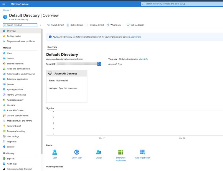
|
| Step 3 |
In the left navigation bar, click App registrations. The App registrations window appears. 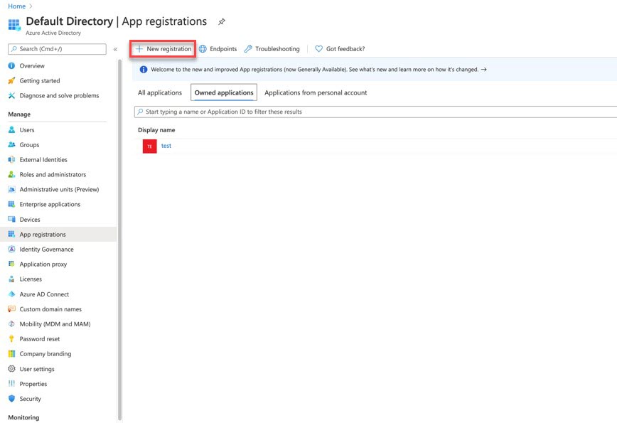
|
| Step 4 |
In the App registrations window, click the New registration at the top of the window. The Register an application window appears. 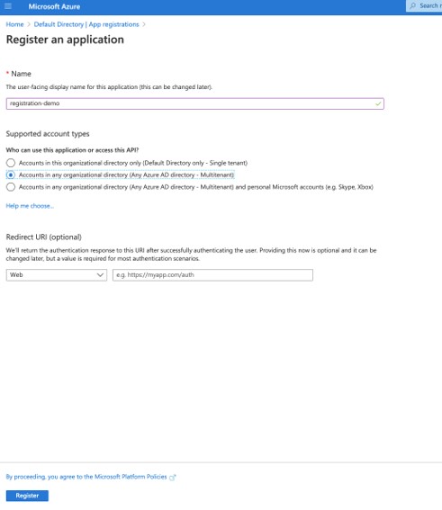
|
| Step 5 |
In the Register an application window, enter the following information and make these selections:
|
| Step 6 |
Click Register. The Certificates & secrets window appears. 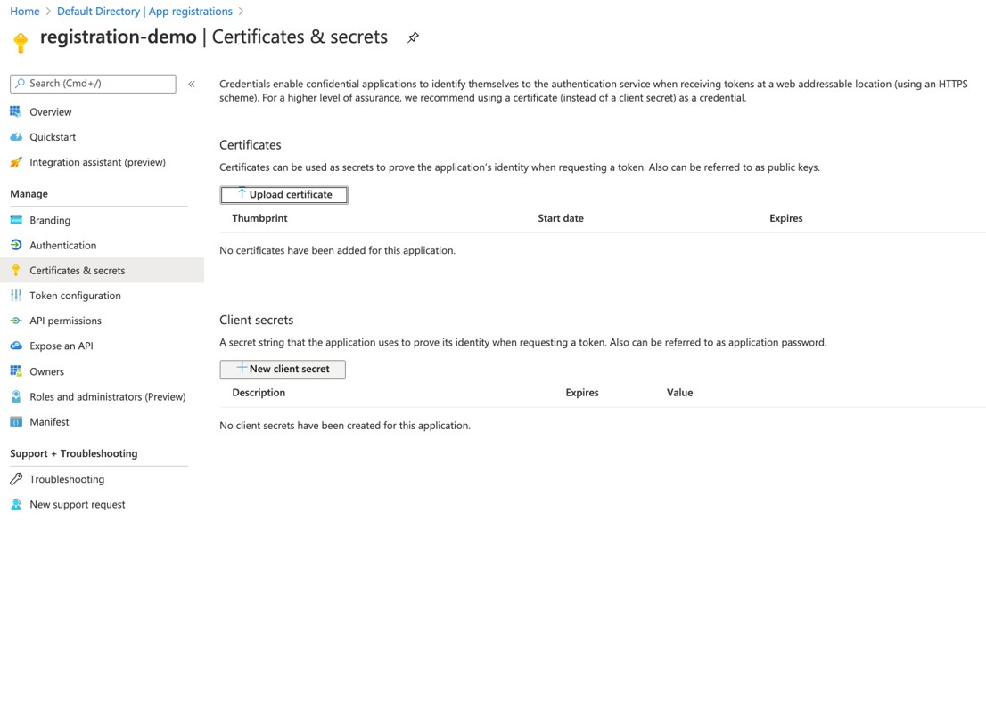
|
| Step 7 |
In the Client secrets area, click New client secret. |
| Step 8 |
Enter a description and expiration period for this client secret, then click Add. 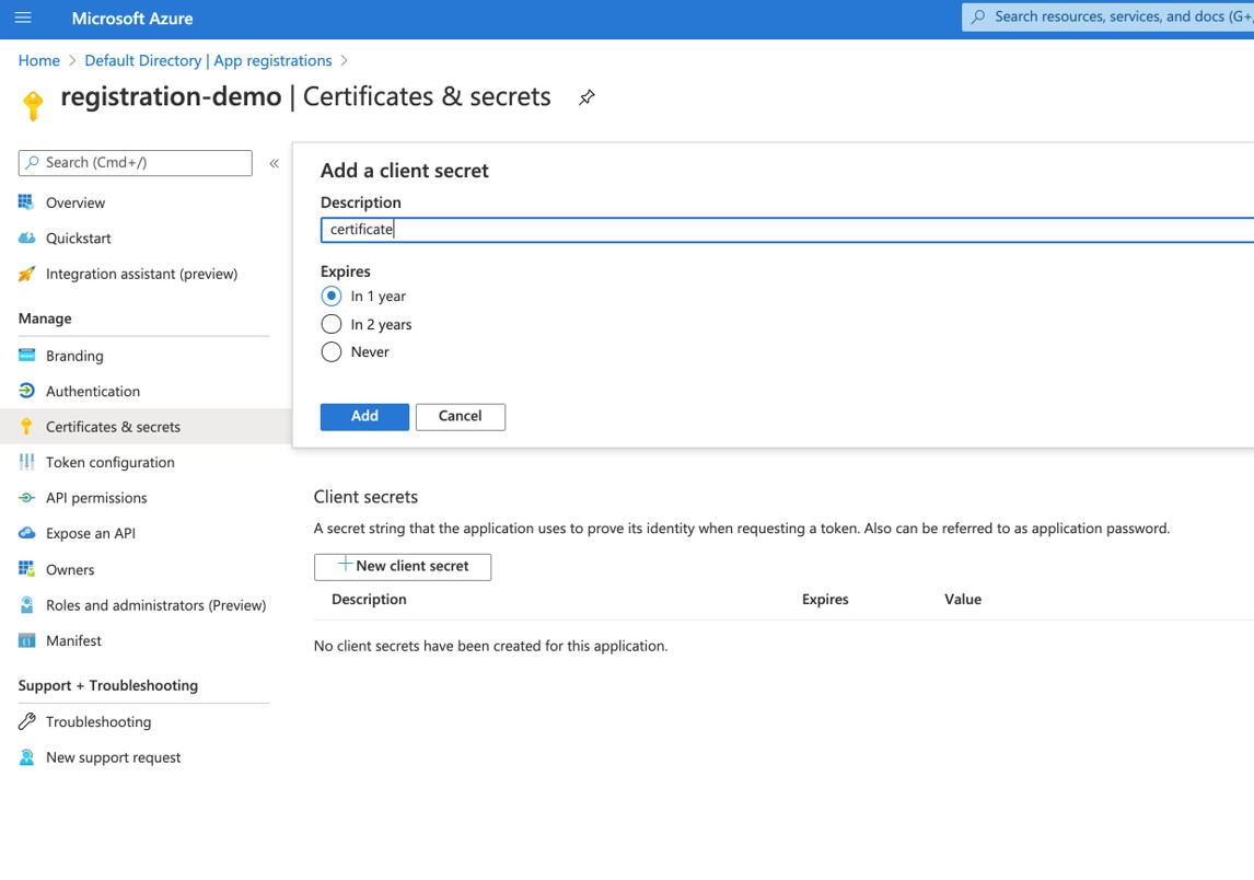
This generates the necessary information that you will need for the Application Secret field later on in these procedures. |
| Step 9 |
Open a text file and copy-and-paste the information in the Value column for the new client secret that you just created. 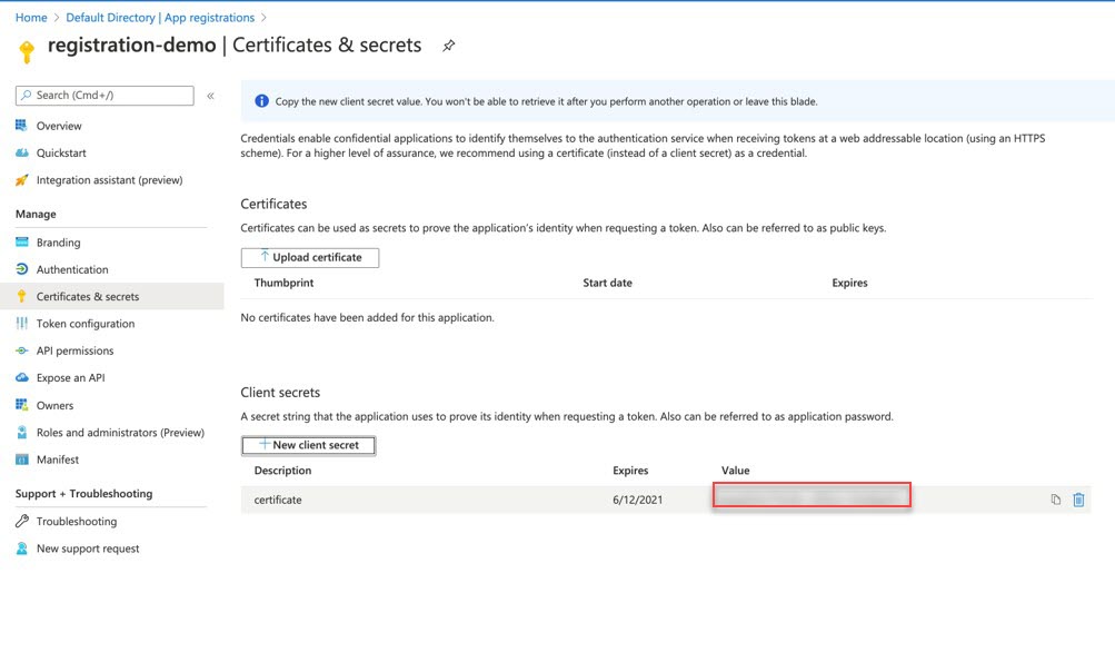
|
| Step 10 |
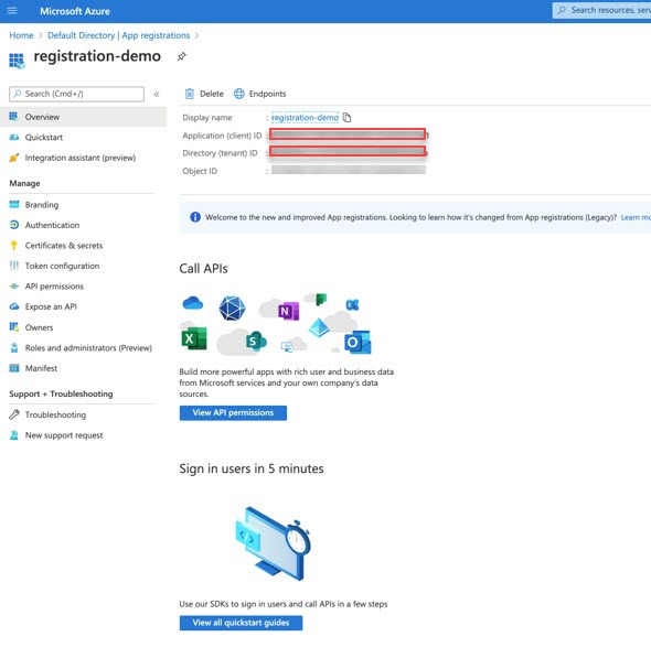
In the left navigation bar, click Overview. |
| Step 11 |
Locate the following fields, then copy-and-paste the values from those fields into the same text file:
|
| Step 12 |
Save the text file and note its location. You will refer to this information when you configure the tenant later on in these procedures. |
| Step 13 |
Log into your Cisco Cloud APIC. |
| Step 14 |
In the left nav panel, click . A list of configured tenants appears. |
| Step 15 |
Determine if you are setting the service principal mode of authorization for the infra tenant or for a user tenant:
|
| Step 16 |
Enter the necessary information in the Name and Security Domain fields. |
| Step 17 |
In the Azure Subscription area, make the following selections:
|
| Step 18 |
Click Save when finished. |
| Step 19 |
Export the application to the other subscription. For more information, see: https://docs.microsoft.com/en-us/azure/virtual-machines/windows/share-images-across-tenants The service principal needs to be exported to the other subscription. For example, assume you have two tenants/apps, anna and bob. The service principal would need to be exported to the other subscription in these ways:
|
| Step 20 |
Configure the Contributor and Network Contributor roles for the tenant subscription. As described in Support for VNet Peering Across Azure Active Directories, you have to configure the roles for Contributor and Network Contributor roles for the infra and user tenants.
For example, assume the following:
Both of these service principals should have Contributor roles on their respective subscriptions to allow the Cisco Cloud APIC to make the calls to create the VNets and establish the VNet peering, where you would make the following configurations:
However, in order to point the peering toward opposite VNets and make the VNet peering connection successful, you also need to make the following configurations:
You can configure the Contributor and Network Contributor roles for the tenant subscription through the GUI or the CLI.
|
Configuring the Contributor and Network Contributor Roles for the Tenant Subscription Using the GUI
These procedures describe how to configure the Contributor and Network Contributor roles for the tenant subscription using the GUI. For instructions on how to configure the Contributor and Network Contributor roles for the tenant subscription using the CLI, see Configuring the Contributor and Network Contributor Roles Using the CLI.
Before you begin
Complete the procedures provided in Configuring Infra and User Tenants With Service Principal Mode of Authorization before proceeding with the procedures in this topic.
Procedure
| Step 1 |
From the main Azure management portal page, click the All services link in the left nav bar, then click the Subscriptions link. 
|
| Step 2 |
In the Subscriptions page in the Azure management portal, click the appropriate subscription account.
The overview information for that subscription is displayed. |
| Step 3 |
Copy-and-paste the subscription ID for the subscription for your Azure account into the text file. 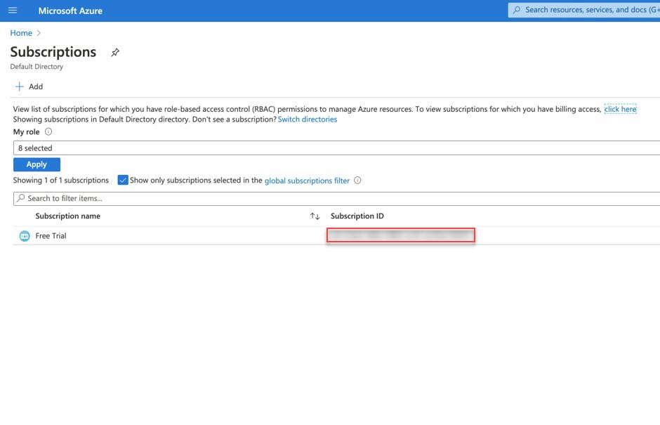 |
| Step 4 |
From the overview page for that subscription, locate the Access control (IAM) link in the left nav bar and click that link. The Access Control page for that subscription is displayed. |
| Step 5 |
Click + Add, then select Add role assignment from the drop-down menu. 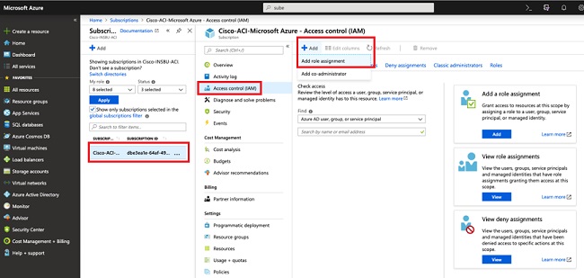
|
| Step 6 |
Add a Contributor role assignment. To configure the Contributor role:
|
| Step 7 |
Add a Network Contributor role assignment. To configure the Network Contributor role:
|
What to do next
When you have configured all of the necessary infra and user tenants with a service principal mode of authorization and you have configured the Contributor and Network Contributor roles for the tenant subscription, enable VNet peering as you normally would. See Configuring Azure VNet Peering Using the GUI for those instructions.
Configuring the Contributor and Network Contributor Roles Using the CLI
These procedures describe how to configure the Contributor and Network Contributor roles for the tenant subscription using the CLI. For instructions on how to configure the Contributor and Network Contributor roles for the tenant subscription using the GUI, see Configuring the Contributor and Network Contributor Roles for the Tenant Subscription Using the GUI.
Before you begin
Complete the procedures provided in Configuring Infra and User Tenants With Service Principal Mode of Authorization before proceeding with the procedures in this topic.
Procedure
| Step 1 |
In the Cisco Cloud APIC GUI, navigate to , then select the appropriate cloud context profile. Note that you should be in the user tenant, not the infra tenant, for these steps. |
| Step 2 |
Copy the az command provided in this window. 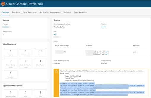
|
| Step 3 |
Return to the Azure management portal and click Registrations in the left navigation bar. |
| Step 4 |
Open the Cloud Shell. |
| Step 5 |
Select Bash. |
| Step 6 |
Assign the Network Contributor roles. |
| Step 7 |
Assign the Contributor roles. |
What to do next
When you have configured all of the necessary infra and user tenants with a service principal mode of authorization and you have configured the Contributor and Network Contributor roles for the tenant subscription, enable VNet peering as you normally would. See Configuring Azure VNet Peering Using the GUI for those instructions.
Guidelines and Limitations for Azure VNet Peering
 Note |
Following are general guidelines and limitations for Azure VNet peering with Cisco Cloud APIC. For guidelines and limitations specifically for the VNet peering across Azure ADs enhancement available in release 5.2(1), see Guidelines and Limitations for Azure VNet Peering Across Azure Active Directories. |
Following are the guidelines and limitations for Azure VNet peering.
-
You can't add, remove, or update a CIDR on the VNet if it has peering connections with other VNets. In this situation, you must remove the VNet peerings, then make the necessary change to the CIDR (add, remove, or update the CIDR), then reestablish the VNet peerings again.
-
Resources in one virtual network can't communicate with the front-end IP address of a Basic Internal Load Balancer (ILB) in a globally-peered virtual network.
-
Some services that use a Basic load balancer don't work over global virtual network peering. For more information, see
-
There is no support for traffic between two user VNets where one of the VNets has only VNet peering configured and the other VNet has only VPN gateway configured.
-
If you are running on release 5.1(1) or earlier and you have the following configuration for your system:
-
VNet peering enabled
-
Multiple cloud sites, each managing multiple regions
-
Two CSRs deployed in each region
And you reboot both CSRs, you might experience a 3-minute traffic loss between the VMs across those cloud sites. Traffic should begin to flow again between the VMs across the cloud sites after several minutes.
-
Prerequisites for Configuring Azure VNet Peering
Complete the following tasks before configuring Azure VNet peering:
-
Install Cisco Cloud APIC.
Follow the instructions in the Cisco Cloud APIC for Azure Installation Guide, Release 5.0(x).
-
Verify that you have set up your sites correctly (on-premises or in the cloud).
Follow instructions in the appropriate Cisco Application Policy Infrastructure Controller (APIC) or Cisco Cloud APIC documentation.
-
If you’re connecting an on-premises site to a cloud site, configure and deploy your on-premises Cisco Application Centric Infrastructure (ACI) fabric and Cisco ACI Multi-Site. Also ensure that you have a MultiSite license.
Configuring Azure VNet Peering Using the GUI
To configure Azure VNet peering, you set up the cloud site and then configure the necessary information in the cloud context profile.
You use Cisco Cloud APIC to set up the cloud site. You can use Cisco Cloud APIC to configure the cloud context profile; however, if you are using Azure VNet peering in a multisite environment, we recommend that you do so in Cisco Application Centric Infrastructure (ACI) Multi-Site Orchestrator.
Set Up the Cloud Site to Use Azure VNet Peering
Complete this task to set up the Azure cloud site to support VNet peering. This procedure assumes that you have not yet set up the cloud site.
The procedure for setting up the cloud site to use Azure VNet peering is very similar to a typical Cloud APIC first-time setup procedure, with the exception of enabling the Azure VNet peering feature using the VNet Peering option, as described in Step 4.
Before you begin
-
Understand the guidelines and limitations provided in Guidelines and Limitations for Azure VNet Peering.
-
Complete the tasks in the section Prerequisites for Configuring Azure VNet Peering.
Procedure
| Step 1 |
Log in to Cisco Cloud APIC. |
| Step 2 |
In the Welcome to Cloud APIC dialog box, click Review First Time Setup. |
| Step 3 |
In the Let's Configure the Basics dialog box, in the Region Management area, click Begin. The Setup—Region Management window appears. |
| Step 4 |
Enable Virtual Network Peering at the global level in the Connectivity for Internal Network area, if necessary. Enabling VNet peering in the Connectivity for Internal Network area enables VNet peering at the global level, which deploys NLBs in all the regions with a CSR.
|
| Step 5 |
If you want connectivity to the on-premises site or another cloud site—in addition to connectivity within this cloud site—check the Inter-Site Connectivity check box. |
| Step 6 |
Locate the Cloud APIC home region and check the box in the Cloud Routers column for the Cloud APIC home region, if it is not checked already. The region that you selected when you were configuring your cloud site is the home region and should be selected already in this page. This is the region where the Cloud APIC is deployed (the region that will be managed by Cloud APIC), and will be indicated with the text Cloud APIC Deployed in the Region column. |
| Step 7 |
In the Regions to Manage area, choose one or more regions that you want to manage. In the current release, a cloud site can consist up to 4 regions, including the home region where the Cloud APIC is deployed. A Cloud APIC can manage multiple cloud regions as a single cloud site. In the current release, a cloud site can consist up to 4 regions, including the home region where the Cloud APIC is deployed. If a Cloud APIC manages two regions, those two regions are considered a single site. The following options are available on the row for any region that you select:
For example, consider the following configuration: 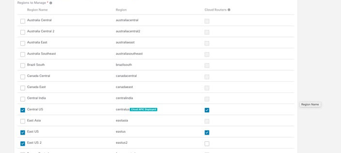
In this example configuration:
|
| Step 8 |
Click Next. Another panel of the Setup—Region Management dialog box appears. The General area shows the subnets for the cloud routers, which you provided when you installed Cisco Cloud APIC. |
| Step 9 |
In the Fabric Autonomous System Number field, enter the BGP autonomous system number (ASN) that is unique to this site. Note the following Microsoft Azure ASN restrictions:
|
| Step 10 |
In the Subnet for Cloud Router field, enter the subnet for the cloud router. The first subnet pool for the first two regions is automatically populated. If you selected more than two regions, you will need to add another subnet for the cloud routers for the additional regions. Addresses from this subnet pool will be used for inter-region connectivity for any additional regions that are added that need to be managed by the Cloud APIC after the first two regions. This must be a valid IPv4 subnet with mask /24. |
| Step 11 |
Click Add Subnet for Cloud Router and enter information for additional subnets, if necessary.
All CIDRs for the infra tenant will be pre-allocated in peering mode. The system needs three /25 subnets for each managed region with CSRs. Click the checkbox to accept the values for every subnet that you add. |
| Step 12 |
Configure the remaining fields as you normally would. |
What to do next
-
Perform the tasks in the chapter "Configuring the Cisco Cloud APIC Using the GUI," in the Cisco Cloud APIC for Azure User Guide 5.0(x).
The tasks include configuring a tenant, an application profile, a VRF, one or more endpoint groups (EPGs), and one or more contracts and filters.
-
Create a cloud context profile for Azure VNET peering.
See Create a Cloud Context Profile for those procedures.
Create a Cloud Context Profile
This section explains how to create a cloud context profile using the Cisco Cloud APIC GUI for Azure VNET peering.
The procedure for creating a cloud context profile for Azure VNet peering is very similar to a typical cloud context profile configuration procedure, with the additional VNet peering-specific step of enabling the Azure VNet peering feature in the VNet Peering field.
Before you begin
Procedure
| Step 1 |
Log in to the Cloud APIC, if you are not logged in already. |
||||||||||||||||||||
| Step 2 |
In the left navigation bar, navigate to . The existing cloud context profiles are displayed. |
||||||||||||||||||||
| Step 3 |
Click Actions and choose Create Cloud Context Profile. The Create Cloud Context Profile dialog box appears. |
||||||||||||||||||||
| Step 4 |
Enter the appropriate values in each field as listed in the following Cloud Context Profile Dialog Box Fields table then continue.
|
||||||||||||||||||||
| Step 5 |
Click Save when finished. |
||||||||||||||||||||
| Step 6 |
Configure the Network Contributor role for both the infra and user tenant subscriptions. For example, assume the following:
In this situation, you will have to configure the following for peering to work between the user tenant and the infra VNets:
|
||||||||||||||||||||
| Step 7 |
Follow these steps to disable Azure VNet peering, if necessary. If you decide that you would like to disable Azure VNet peering after you have configured it, follow these steps to disable the VNet peering feature:
|
||||||||||||||||||||
Configuring Azure VNet Peering Using the REST API
Complete this task to set up the Azure cloud site to support VNet peering. This procedure assumes that you have not yet set up the cloud site.
Before you begin
-
Understand the guidelines and limitations provided in Guidelines and Limitations for Azure VNet Peering.
-
Complete the tasks in the section Prerequisites for Configuring Azure VNet Peering.
Procedure
| Step 1 |
Configure the cloud template for the infra tenant using a post such as the following, where the information used to configure Azure VNet peering is highlighted in bold. |
||
| Step 2 |
Configure the cloud context profile for the user tenant using a post such as the following, where the information used to configure Azure VNet peering is highlighted in bold.
|
Verifying the Azure VNet Peering Deployment
After you configure Azure VNet peering, you should verify that it is deployed correctly.
Before you begin
You must have set up the cloud site and configured the cloud context profile.
Procedure
| Step 1 |
Log into Cisco Cloud Application Policy Infrastructure Controller (Cloud APIC). |
| Step 2 |
In the left navigation pane, choose . |
| Step 3 |
Verify that the information shown in the Virtual Network Peering area is correct. 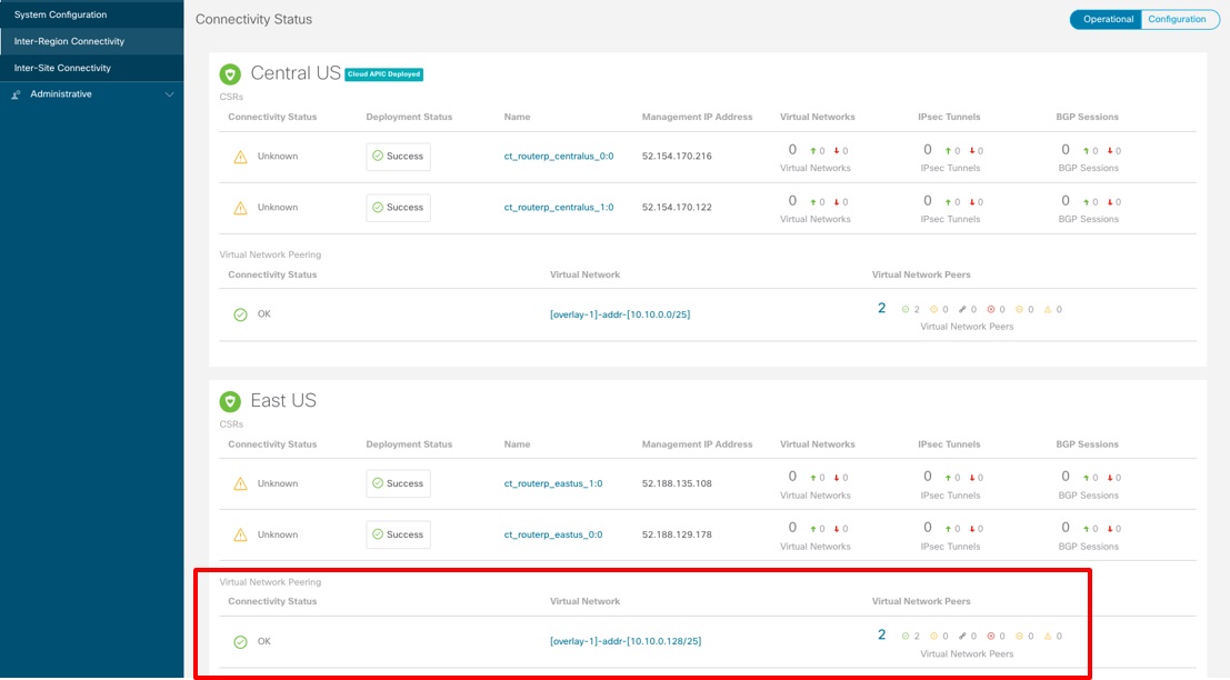
|
| Step 4 |
Click on the count (the blue number 2 in the example above) to display more detailed information. This will display peerings from the hub VNet to the tenant VNets. 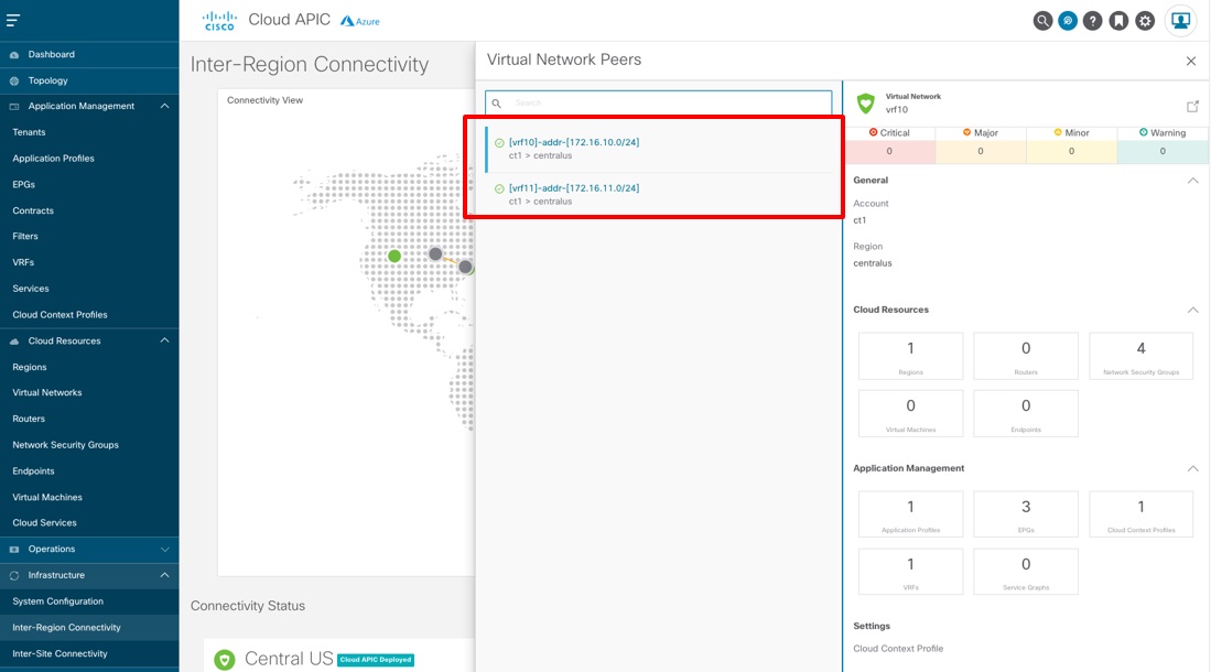 |
| Step 5 |
In the left navigation pane, choose , then click the Cloud Resources tab. The information displayed in this window shows the bi-directional peerings. 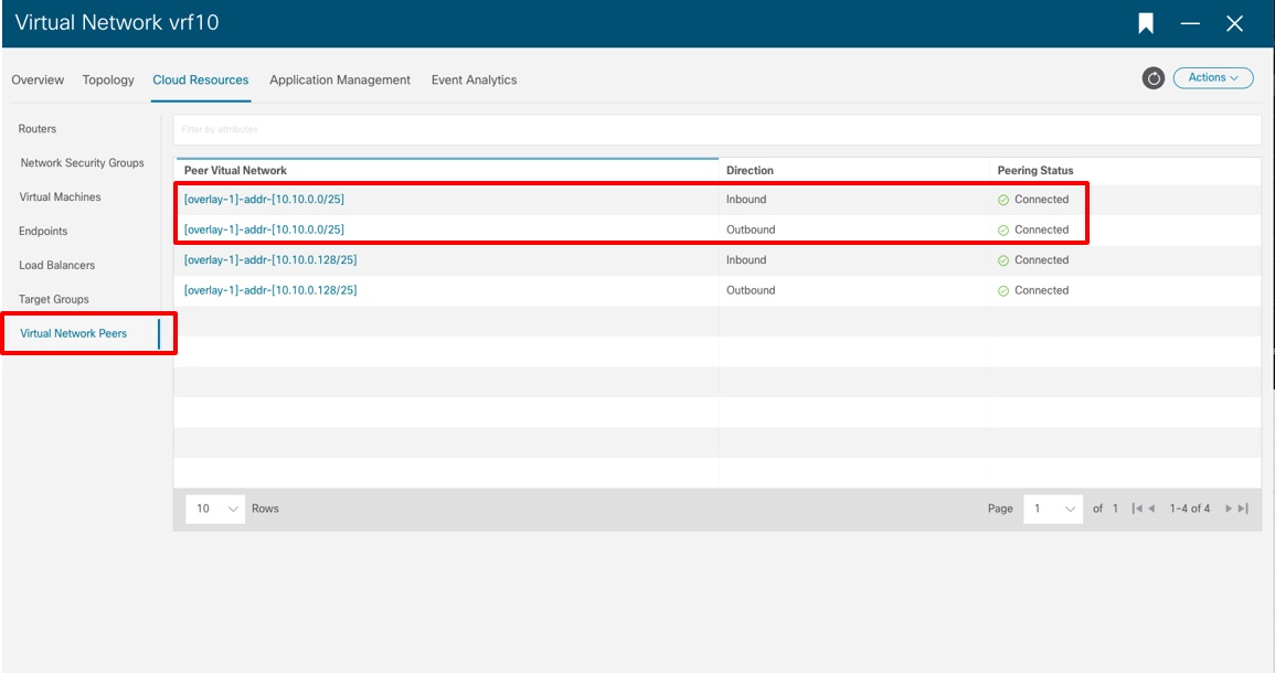
|
| Step 6 |
To check routes, in the same page, click the Overview tab. UDRs (routes) for peering are driven by contracts defined between EPGs. Check the configuration for contracts if routes are not present. For each subnet shown in the main window, you can also see the current route table, as shown in the following figure. 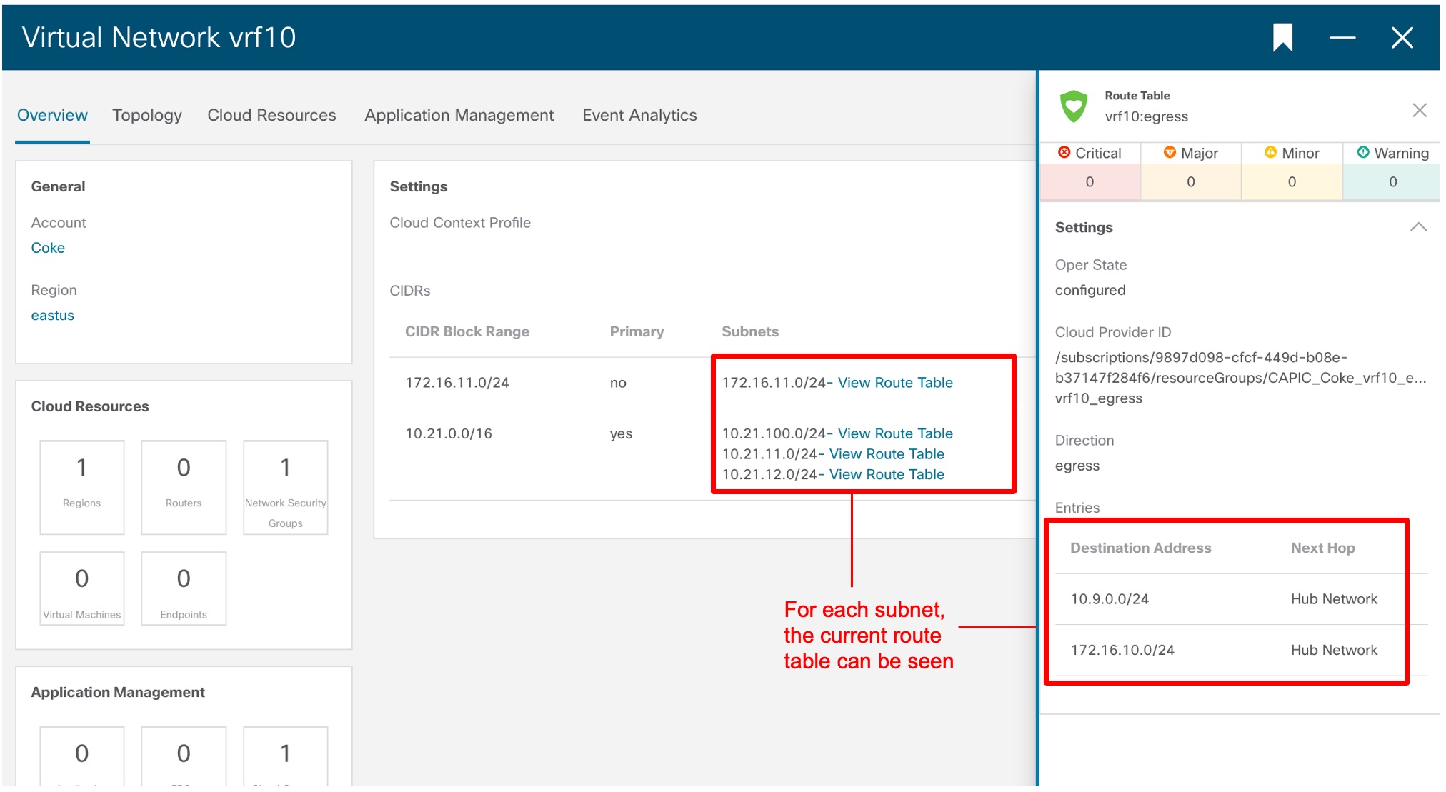
|
Trademarks
THE SPECIFICATIONS AND INFORMATION REGARDING THE PRODUCTS REFERENCED IN THIS DOCUMENTATION ARE SUBJECT TO CHANGE WITHOUT NOTICE. EXCEPT AS MAY OTHERWISE BE AGREED BY CISCO IN WRITING, ALL STATEMENTS, INFORMATION, AND RECOMMENDATIONS IN THIS DOCUMENTATION ARE PRESENTED WITHOUT WARRANTY OF ANY KIND, EXPRESS OR IMPLIED.
The Cisco End User License Agreement and any supplemental license terms govern your use of any Cisco software, including this product documentation, and are located at: http://www.cisco.com/go/softwareterms.Cisco product warranty information is available at http://www.cisco.com/go/warranty. US Federal Communications Commission Notices are found here http://www.cisco.com/c/en/us/products/us-fcc-notice.html.
IN NO EVENT SHALL CISCO OR ITS SUPPLIERS BE LIABLE FOR ANY INDIRECT, SPECIAL, CONSEQUENTIAL, OR INCIDENTAL DAMAGES, INCLUDING, WITHOUT LIMITATION, LOST PROFITS OR LOSS OR DAMAGE TO DATA ARISING OUT OF THE USE OR INABILITY TO USE THIS MANUAL, EVEN IF CISCO OR ITS SUPPLIERS HAVE BEEN ADVISED OF THE POSSIBILITY OF SUCH DAMAGES.
Any products and features described herein as in development or available at a future date remain in varying stages of development and will be offered on a when-and if-available basis. Any such product or feature roadmaps are subject to change at the sole discretion of Cisco and Cisco will have no liability for delay in the delivery or failure to deliver any products or feature roadmap items that may be set forth in this document.
Any Internet Protocol (IP) addresses and phone numbers used in this document are not intended to be actual addresses and phone numbers. Any examples, command display output, network topology diagrams, and other figures included in the document are shown for illustrative purposes only. Any use of actual IP addresses or phone numbers in illustrative content is unintentional and coincidental.
The documentation set for this product strives to use bias-free language. For the purposes of this documentation set, bias-free is defined as language that does not imply discrimination based on age, disability, gender, racial identity, ethnic identity, sexual orientation, socioeconomic status, and intersectionality. Exceptions may be present in the documentation due to language that is hardcoded in the user interfaces of the product software, language used based on RFP documentation, or language that is used by a referenced third-party product.
Cisco and the Cisco logo are trademarks or registered trademarks of Cisco and/or its affiliates in the U.S. and other countries. To view a list of Cisco trademarks, go to this URL: www.cisco.com go trademarks. Third-party trademarks mentioned are the property of their respective owners. The use of the word partner does not imply a partnership relationship between Cisco and any other company. (1721R)
 Feedback