New and Changed Information
The following table provides an overview of the significant changes to this document.
|
Cisco NDB Release Version |
Feature |
Description |
|---|---|---|
|
3.9 |
Packet Truncation |
This document has details of how to implement Packet Truncation. |
Packet Truncation
Packet truncation, also called as packet slicing, involves discarding bytes from a packet. Only a portion of the packet (initial bytes of the packet header) is saved instead of the entire packet, after a user-specified byte position is discarded. This helps in reducing the data overload on tools.
Packet truncation enables users to perform header analytics efficiently on the main information in the initial part of the packet . This helps in tools optimization like improving tools performance by eliminating transmission of the unnecessary part of the packet payload and increases storage capacity, by giving tools more room to store the important portions of each packet.
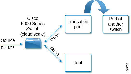
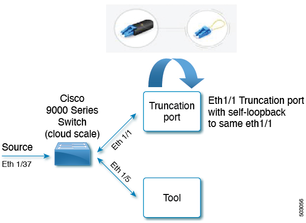
Consider the following topology - Cisco Nexus 9000 Series switch with source port (Ethernet 1/37) , truncation port (Ethernet 1/1) and delivery port (Ethernet 1/5). Packet truncation can be implemented in either of these two ways:
-
Truncation port of the NDB switch is connected to another switch (or can also be another port on the same NDB switch).

-
Truncation port of the NDB switch uses self loopback modules. Self loopback modules are special transceivers.

Packet truncation is supported on the following Nexus 9000 series switches:
|
EX Chassis |
FX Chassis |
Nexus 9364C, Nexus 9332C |
Nexus 9336C-FX2 |
EOR switches with -EX or -FX LCs |
|---|---|---|---|---|
|
Support started from NX-OS Release 7.0(3)I7(1) |
Support started from NX-OS Release 7.0(3)I7(1) |
Support started from NX-OS Release 7.0(3)I7(2) |
Support started from NX-OS Release 7.0(3)I7(3) |
9.3(1) |
|
MTU size range is 320 to 1518 bytes |
MTU size range is 64 to 1518 bytes |
MTU size range is 64 to 1518 bytes |
MTU size range is 64 to 1518 bytes |
Depends on LC |
|
Four active localized SPAN sessions |
Four active localized SPAN sessions |
Four active localized SPAN sessions |
Four active localized SPAN sessions |
- |
Refer the respective switch documentation, for more information about Nexus 9000 series switches.
Guidelines and Limitations
-
Packet truncation is supported for unicast traffic only (not supported for multicast traffic).
-
Packet truncation port and delivery/monitor port should be present on the same switch.
Workflow for Packet Truncation
The following table lists the tasks for the workflow. Complete the tasks in the order as indicated in the table.
|
Task |
Description |
Result of the Task (Examples used in the task are indicated here) |
|---|---|---|
|
Creates a packet truncation port. |
Truncation_port was created. |
|
|
Creates an edge span port. |
Span_port was created. |
|
|
Creates a delivery port. |
Tool_port was created. |
|
|
Creates a connection between the edge span port and delivery port. |
The default match all filter is used. |
Creating a Packet Truncation Port
Use this procedure to configure a packet truncation interface.
Procedure
|
Step 1 |
Navigate to Configuration > Port Definition > Port Configuration. |
|
Step 2 |
Click Configure for the interface selected for configuration. |
|
Step 3 |
In the Configure Ports pane, click Select a port type and click Packet Truncation Port. |
|
Step 4 |
In the Port Description field, enter the name as Truncation_port. |
|
Step 5 |
Click Submit. A packet truncation port is created to block the ingress traffic. |
What to do next
interface Ethernet1/1
	description Truncation_Port
	switchport mode trunk
	ip port access-group ndb_ipacl_Ethernet1_1 in
	ipv6 port traffic-filter ndb_ipv6acl_Ethernet1_1 in
	mac port access-group ndb_macacl_Ethernet1_1
	mode tap-aggregation
	spanning-tree bpdufilter enable
Creating an Edge Span Port
Use this procedure to create an edge span port, which is the ingress port for the packet.
Procedure
|
Step 1 |
Navigate to Configuration > Port Definitions > Port Configuration. |
|
Step 2 |
Click Configure on the port to be configured as the span port. The Configure Ports window is displayed. |
|
Step 3 |
Select Edge Port - SPAN from the drop-down menu. |
|
Step 4 |
In the Port Description field, enter Span_port. |
|
Step 5 |
Click Submit. |
What to do next
Use the show running-config command to check the configurations of the span port. Details for the source port displayed below, are based on the topology discussed in the Packet Truncation section.
interface Ethernet1/37
	description Span_Port
	no lldp transmit
	no lldp receive
	switchport mode trunk
	ip port access-group ndb_ipacl_Ethernet1_37 in
	ipv6 port traffic-filter ndb_ipv6acl_Ethernet1_37 in
	mac port access-group ndb_macacl_Ethernet1_37
	mode tap-aggregation
	spanning-tree bpdufilter enable
	switchport block multicast
	switchport block unicast
Creating a Delivery Port
Use this procedure to create a delivery (monitoring tool) port, which is the egress port for the packet.
Procedure
|
Step 1 |
Navigate to Configuration > Port Definitions > Port Configuration. |
|
Step 2 |
Click Configure on the port to be configured as the monitor tool port. |
|
Step 3 |
Select Add Monitoring Device . The Add Monitoring Device window is displayed. |
|
Step 4 |
In the Monitoring Device Name field, enter Tool_port. |
|
Step 5 |
Check the Packet Truncation checkbox. |
|
Step 6 |
In the MTU Size field, enter the MTU size in bytes. Packet truncation is based on the set MTU size. |
|
Step 7 |
Select the configured packet truncation port from the drop-down list. |
|
Step 8 |
Click Submit. |
What to do next
interface Ethernet1/5
	no lldp transmit
	no lldp receive
	switchport mode trunk
	ip port access-group ndb_ipacl_Ethernet1_5 in
	ipv6 port traffic-filter ndb_ipv6acl_Ethernet_5 in
	mac port access-group ndb_macacl_Ethernet1_5
	mode tap-aggregation
	spanning-tree bpdufilter enable
session 1
---------
description        :NDB-session
type               :local
state		 :up
acl-name	     :acl-name1
mtu		    :500
source intf	   :
	rx	     :
	tx	     :Eth1/1
	both	   :
source VLANs	  :
	rx	     :
	tx	     :
	both	   :
filter VLANs	  :filter not specified
source fwd drops     :
destination ports    :ETh1/5
source VSANs	:
Creating a Connection using Filters
Use this procedure to create a connection using the default match-all filter.
Procedure
|
Step 1 |
Navigate to Configuration > Connections > User Connections. |
|
Step 2 |
Click New Connection. The Add Connection window is displayed. |
|
Step 3 |
In the Connection Details pane, enter a name in the Connection Name field. Enter the connection name as Packet_Truncation_Connection. |
|
Step 4 |
In the Filter Details pane, select the Default Match_all filter from the Allow Filters drop-down menu. |
|
Step 5 |
In the Destination Device/ Destination Group Details pane, select the Source and Destination ports. Choose Span_port and Tool_port, based on the earlier configurations. |
|
Step 6 |
Click Install Connection to install the connection in the switch. |
What to do next
Use the show ip access-lists command to check the latest configuration updates to the switch, after the connection is established.
IP access list ndb_ipacl_Ethernet1/37
	statistics per-entry
	49500001 permit any any redirect Ehernet1/1 (match=0)
	49993001 deny ip any any (match=0)
Validating Traffic
This task describes how to confirm packet truncation based on MTU size. MTU size for the delivery port is set to 500 bytes.
Before you begin
Send traffic from the production switch with 1500 bytes.
Procedure
|
Step 1 |
Use the show ip access-lists command to check the acl counter. |
|
Step 2 |
Use the show interface command for the source port and check the size of the received bytes. The Inoctets column for the source port (Eth1/37) displays 1504 bytes.
|
|
Step 3 |
Use the show interface command for the trunction port. The Outoctets column for the truncation port (Eth1/1) displays 1500 bytes.
|
|
Step 4 |
Use the show interface command for the monitor port. The Outoctets column for the monitor port (Eth1/5) displays 500 bytes, based on the set MTU size. The received 1500 bytes packet is truncated
to 500 bytes and sent to the tool.
|
 Feedback