
Pod Profile and Policy Group
In each fabric’s APIC, you must have one Pod profile with a Pod policy group. If your fabric does not have a Pod policy group you must create one. Typically, these settings will already exist as you will have configured them when you first deployed the fabric.
-
Log in to the fabric’s APIC GUI.
-
Check that the Pod profile contains a Pod policy group.
Navigate to Fabric > Fabric Policies > Pods > Profiles > Pod Profile default.
-
If necessary, create a Pod policy group.
-
Navigate to Fabric > Fabric Policies > Pods > Policy Groups.
-
Right-click Policy Groups and select Create Pod Policy Group.
-
Enter the appropriate information and click Submit.
-
-
Assign the new Pod policy group to the default Pod profile.
-
Navigate to Fabric > Fabric Policies > Pods > Profiles > Pod Profile default
-
Select the default profile.
-
Choose the new pod policy group and click Update.
-
Configuring Fabric Access Policies for All APIC Fabrics
Before your APIC fabrics can be added to and managed by the Nexus Dashboard Orchestrator, there is a number of fabric-specific access policies that you must configure on each fabric.
Configuring Fabric Access Global Policies
This section describes the global fabric access policy configurations that must be created for each APIC fabric before it can be added to and managed by the Nexus Dashboard Orchestrator.
-
Log in directly to the fabric’s APIC GUI.
-
From the main navigation menu, select Fabric > Access Policies.
You must configure a number of fabric policies before the fabric can be added to the Nexus Dashboard Orchestrator. From the APIC’s perspective, this is something you do just like you would if you were connecting a bare-metal host, where you would configure domains, AEPs, policy groups, and interface selectors; you must configure the same options for connecting the spine switch interfaces to the inter-fabric network for all the fabrics that will be part of the same Multi-Fabric domain.
-
Specify the VLAN pool.
The first thing you configure is the VLAN pool. We use Layer 3 sub-interfaces tagging traffic with VLAN-4 to connect the spine switches to the inter-fabric network.
-
In the left navigation tree, browse to Pools > VLAN.
-
Right-click the VLAN category and choose Create VLAN Pool.
In the Create VLAN Pool window, specify the following:
-
For the Name field, specify the name for the VLAN pool, for example
mfabric. -
For Allocation Mode, specify
Static Allocation. -
And for the Encap Blocks, specify just the single VLAN 4. You can specify a single VLAN by entering the same number in both Range fields.
-
-
-
Configure Attachable Access Entity Profiles (AEP).
-
In the left navigation tree, browse to Global Policies > Attachable Access Entity Profiles.
-
Right-click the Attachable Access Entity Profiles category and choose Create Attachable Access Entity Profiles.
In the Create Attachable Access Entity Profiles window, specify the name for the AEP, for example
mfabric-aep. -
Click Next and Submit
No additional changes, such as interfaces, are required.
-
-
Configure domain.
The domain you configure is what you will select from the Nexus Dashboard Orchestrator when adding this fabric.
-
In the left navigation tree, browse to Physical and External Domains > External Routed Domains.
-
Right-click the External Routed Domains category and choose Create Layer 3 Domain.
In the Create Layer 3 Domain window, specify the following:
-
For the Name field, specify the name the domain, for example
mfabric-l3. -
For Associated Attachable Entity Profile, select the AEP you created in Step 4.
-
For the VLAN Pool, select the VLAN pool you created in Step 3.
-
-
Click Submit.
No additional changes, such as security domains, are required.
-
After you have configured the global access policies, you must still add interfaces policies as described in Configuring Fabric Access Interface Policies.
Configuring Fabric Access Interface Policies
You must have configured the global fabric access policies, such as VLAN Pool, AEP, and domain, in the fabric’s APIC, as described in Configuring Fabric Access Global Policies.
This section describes the fabric access interface configurations that must be done for the Nexus Dashboard Orchestrator on each APIC fabric.
-
Log in directly to the fabric’s APIC GUI.
-
From the main navigation menu, select Fabric > Access Policies.
In addition to the VLAN, AEP, and domain you have configured in previous section, you must also create the interface policies for the fabric’s spine switch interfaces that connect to the Inter-Fabric Network.
-
Configure a spine policy group.
-
In the left navigation tree, browse to Interface Policies > Policy Groups > Spine Policy Groups.
This is similar to how you would add a bare-metal server, except instead of a Leaf Policy Group, you are creating a Spine Policy Group.
-
Right-click the Spine Policy Groups category and choose Create Spine Access Port Policy Group.
In the Create Spine Access Port Policy Group window, specify the following:
-
For the Name field, specify the name for the policy group, for example
Spine1-PolGrp. -
For the Link Level Policy field, specify the link policy used between your spine switch and the ISN.
-
For CDP Policy, choose whether you want to enable CDP.
-
For the Attached Entity Profile, select the AEP you have configured in previous section, for example
mfabric-aep.
-
-
Click Submit.
No additional changes, such as security domains, are required.
-
-
Configure a spine profile.
-
In the left navigation tree, browse to Interface Policies > Profiles > Spine Profiles.
-
Right-click the Spine Profiles category and choose Create Spine Interface Profile.
In the Create Spine Interface Profile window, specify the following:
-
For the Name field, specify the name for the profile, for example
Spine1-ISN. -
For Interface Selectors, click the + sign to add the port on the spine switch that connects to the ISN. Then in the Create Spine Access Port Selector window, provide the following:
-
For the Name field, specify the name for the port selector, for example
Spine1-ISN. -
For the Interface IDs, specify the switch port that connects to the ISN, for example
5/32. -
For the Interface Policy Group, choose the policy group you created in the previous step, for example
Spine1-PolGrp.
Then click OK to save the port selector.
-
-
-
Click Submit to save the spine interface profile.
-
-
Configure a spine switch selector policy.
-
In the left navigation tree, browse to Switch Policies > Profiles > Spine Profiles.
-
Right-click the Spine Profiles category and choose Create Spine Profile.
In the Create Spine Profile window, specify the following:
-
For the Name field, specify the name for the profile, for example
Spine1. -
For Spine Selectors, click the + to add the spine and provide the following:
-
For the Name field, specify the name for the selector, for example
Spine1. -
For the Blocks field, specify the spine node, for example
201.
-
-
-
Click Update to save the selector.
-
Click Next to proceed to the next screen.
-
Select the interface profile you have created in the previous step
For example
Spine1-ISN. -
Click Finish to save the spine profile.
-
Configuring Fabrics That Contain Remote Leaf Switches
Nexus Dashboard Orchestrator architecture supports ACI fabrics with Remote Leaf switches. The following sections describe guidelines, limitations, and configuration steps required to allow Nexus Dashboard Orchestrator to manage these fabrics.
Remote Leaf
Remote leaf switches are leaf nodes that connect to the ACI Main Datacenter (DC) through a generic Inter-Pod Network (IPN). The remote leaf feature enables the extension of connectivity and the implementation of consistent policies to remote locations where deploying a complete ACI Pod (including leaf and spine nodes) may not be feasible or desirable. A remote location might consist of a small data center that does not require an extensive number of leaf switches for connectivity. These remote leaf switches establish connections back to spine nodes in the main ACI data center. These remote leaf switches are fully integrated into an existing pod within the fabric, operating like any standard leaf switch in that pod.
Cisco Nexus Dashboard Orchestrator facilitates centralized policy definition (intent) and management, providing the following functionalities:
-
Monitoring the health-state of the different ACI fabrics.
-
Provisioning of day-0 configuration to establish inter-fabric EVPN control plane.
-
Defining and provisioning policies across fabrics (scope of changes).
-
Inter-fabric troubleshooting.
-
Disaster Recovery
-
Multi-cloud connectivity
Before Cisco Nexus Dashboard Orchestrator (NDO) Release 4.4(1), remote leaf switches were managed by the orchestrator in the same way as any standard leaf switch, without differentiating between local and remote switches.
The remote leaf fabric uplink port was limited to control and data plane (VXLAN) connectivity to the main ACI pod using sub-interface VLAN 4, with no additional sub-interfaces permitted on the same uplink port. For a remote leaf switch with L3Out connected to the same device as the fabric IPN links, two separate uplinks from the IPN were necessary to provision connectivity, requiring distinct interfaces for fabric and L3Out connections.
Beginning with Cisco Nexus Dashboard Orchestrator Release 4.4(1) on Remote Leaf switches with ACI Release 6.1(1), the orchestrator can now distinguishes between local and remote leaf types, enabling the management of functions unique to remote leaf switches. Recent ACI releases have introduced new functionalities that specifically cater to remote leaf switches.
This enhancement allows for the utilization of a single uplink for both the fabric control and data plane connectivity on sub-interface VLAN 4, while also permitting the configuration of additional sub-interfaces for tenant L3Out (VRF-Lite) and SR-MPLS infrastructure L3Outs.
It is important to note that the tenant and SR-MPLS L3Outs cannot utilize sub-interface VLAN 4, as this is reserved for the remote leaf fabric interface. For more details on tenant L3Out from a remote leaf, please refer to the Cisco ACI Remote Leaf Architecture White Paper.
Remote Leaf Guidelines and Limitations
If you want to add an APIC fabric with a Remote Leaf to be managed by the Nexus Dashboard Orchestrator, the following guidelines and restrictions apply:
-
You must upgrade your Cisco APIC to Release 4.2(4) or later.
-
You can now use the same fabric port, used earlier for VXLAN connectivity with ACI Fabric to provide connectivity toward the external network domain using local L3Out(s). For more information on tenant policy templates and L3Out configuration, see the Creating L3Out Template.
-
Only -EX and -FX or later switches are supported as Remote Leaf switches for use with Multi-Fabric
-
Remote Leaf is not supported with back-to-back connected fabrics without IPN switches.
-
Remote Leaf switches in one fabric cannot use another fabric’s L3Out.
-
When a bridge domain is deployed to a remote leaf switch it must be local only to the fabric where the remote leaf belongs. Stretching a bridge domain deployed on a remote leaf switch to another fabric is not supported.
You must also perform the following tasks before the fabric can be added to and managed by the Nexus Dashboard Orchestrator:
-
You must add the routable IP addresses of Cisco APIC nodes in the DHCP-Relay configuration applied on the interfaces of the Layer 3 routers connecting to the Remote Leaf switches.
-
You must enable Remote Leaf direct communication and configure routable subnets directly in the fabric’s {FabricControllerShortName}, as described in the following sections.
The routable IP address of each APIC node is listed in the Routable IP field of the System > Controllers > <controller-name> screen of the APIC GUI.
Configuring Routable Subnets for Remote Leaf Switches
-
Upgrade Cisco APIC and all the nodes in the fabric to Release 4.1(2) or later.
-
Verify that the routes for the Routable Subnet that you wish to configure will be reachable in the Inter-Pod Network (IPN), and that the subnet is reachable from the remote leaf switches.
Before you can add a fabric that contains one or more Remote Leaf switches to the Nexus Dashboard Orchestrator, you must configure routable subnets for the pod with which the Remote Leaf nodes are associated.
-
Log in directly to the fabric’s {FabricControllerShortName} GUI.
-
From the menu bar, select Fabric > Inventory.
-
In the Navigation pane, click Pod Fabric Setup Policy.
-
On the Fabric Setup Policy panel, double-click the pod where you want to configure routable subnets.
-
Access the information in the subnets or TEP table, depending on the release of your APIC software:
-
For releases prior to 4.2(3), click the
+on the Routable Subnets table. -
For 4.2(3) only, click the
+on the External Subnets table. -
For 4.2(4) and later, click the
+on the External TEP table.
-
-
Enter the IP address and Reserve Address, if necessary, and set the state to active or inactive.
-
The IP address is the subnet prefix that you wish to configure as the routeable IP space.
-
The Reserve Address is a count of addresses within the subnet that must not be allocated dynamically to the spine switches and remote leaf switches. The count always begins with the first IP in the subnet and increments sequentially. If you wish to allocate the Unicast TEP (covered later in these procedures) from this pool, then it must be reserved.
-
-
Click Update to add the external routable subnet to the subnets or TEP table.
-
On the Fabric Setup Policy panel, click Submit.

If you find that you have to make changes to the information in the subnets or TEP table after you’ve made these configurations, follow the procedures provided in "Changing the External Routable Subnet" in the Cisco APIC Getting Started Guide to make those changes successfully.
Enabling Direct Communication for Remote Leaf Switches
Before you can add a fabric that contains one or more Remote Leaf switches to the Nexus Dashboard Orchestrator, you must configure direct remote leaf communication for that fabric. Additional information about remote leaf direct communication feature is available in the Cisco APIC Layer 3 Networking Configuration Guide. This section outlines the steps and guidelines specific to the integration with Multi-Fabric.
Once you enable Remote Leaf switch direct communication, the switches will function in the new mode only
-
Log in directly to the fabric’s {FabricControllerShortName}.
-
Enable direct traffic forwarding for Remote Leaf switches.
-
From the menu bar, navigate to System > System Settings.
-
From the left side bar, select Fabric Wide Setting.
-
Check the Enable Remote Leaf Direct Traffic Forwarding checkbox.
When this is enabled, the spine switches will install Access Control Lists (ACLs) to prevent traffic coming from remote leaf switches from being sent back, since the remote leaf switches will now send directly between each remote leaf switches' TEPs. There may be a brief disruption in service while the tunnels are built between the remote leaf switches.
-
Click Submit to save the changes.
-
-
To verify that the configuration was set correctly, on the spine switch, enter the following command:
spine# cat /mit/sys/summary
You should see the following highlighted line in the output, which is verification that the configuration was set correctly (full output truncated):podId : 1 remoteNetworkId : 0 remoteNode : no rldirectMode : yes rn : sys role : spine
Cisco Mini ACI Fabrics
Cisco Multi-Fabric supports Cisco Mini ACI fabrics as typical on-premises fabrics without requiring any additional configuration. This section provides a brief overview of Mini ACI fabrics, detailed info on deploying and configuring this type of fabrics is available in Cisco Mini ACI Fabric and Virtual APICs.
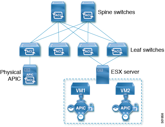
Cisco ACI, Release 4.0(1) introduced Mini ACI Fabric for small scale deployment. Mini ACI fabric works with [CiscoAPICShortName] cluster consisting of one physical APIC and two virtual APICs (vAPIC) running in virtual machines. This reduces the physical footprint and cost of the APIC cluster, allowing ACI fabric to be deployed in scenarios with limited rack space or initial budget, such as a colocation facility or a single-room data center, where a full-scale ACI installations may not be practical due to physical footprint or initial cost.
The following diagram shows an example of a mini [CiscoACIShortName2] fabric with a physical APIC and two virtual APICs (vAPICs):
Adding and Deleting Fabrics
Cisco NDO and APIC Interoperability Support
Cisco Nexus Dashboard Orchestrator (NDO) does not require a specific version of APIC to be running in all fabrics. The APIC clusters in each fabric as well as the NDO itself can be upgraded independently of each other and run in mixed operation mode as long as the fabric can be on-boarded to the Nexus Dashboard where the Nexus Dashboard Orchestrator service is installed. As such, we recommend that you always upgrade to the latest release of the Nexus Dashboard Orchestrator.
However, keep in mind that if you upgrade the NDO before upgrading the APIC clusters in one or more fabrics, some of the new NDO features may not yet be supported by an earlier APIC release. In that case a check is performed on each template to ensure that every configured option is supported by the target fabrics.
The check is performed when you save a template or deploy a template. If the template is already assigned to a fabric, any unsupported configuration options will not be saved; if the template is not yet assigned, you will be able to assign it to a fabric, but not be able to save or deploy the schema if it contains configuration unsupported by that fabric.
In case an unsupported configuration is detected, an error message will show, for example: This APIC fabric version <fabric-version> is not supported by NDO. The minimum version required for this <feature> is <required-version> or above.
The following table lists the features and the minimum required APIC release for each one:
While some of the following features are supported on earlier Cisco APIC releases, Release 4.2(4) is the earliest release that can be on-boarded to the Nexus Dashboard and managed by this release of Nexus Dashboard Orchestrator.
| Feature | Minimum APIC Version |
|---|---|
|
ACI Multi-Pod Support |
Release 4.2(4) |
|
Service Graphs (L4-L7 Services) |
Release 4.2(4) |
|
External EPGs |
Release 4.2(4) |
|
ACI Virtual Edge VMM Support |
Release 4.2(4) |
|
DHCP Support |
Release 4.2(4) |
|
Consistency Checker |
Release 4.2(4) |
|
vzAny |
Release 4.2(4) |
|
Host Based Routing |
Release 4.2(4) |
|
CloudSec Encryption |
Release 4.2(4) |
|
Layer 3 Multicast |
Release 4.2(4) |
|
MD5 Authentication for OSPF |
Release 4.2(4) |
|
EPG Preferred Group |
Release 4.2(4) |
|
Inter-Fabric L3Out |
Release 4.2(4) |
|
EPG QoS Priority |
Release 4.2(4) |
|
Contract QoS Priority |
Release 4.2(4) |
|
Single Sign-On (SSO) |
Release 5.0(1) |
|
Multicast Rendezvous Point (RP) Support |
Release 5.0(1) |
|
Transit Gateway (TGW) support for AWS and Azure Fabrics |
Release 5.0(1) |
|
SR-MPLS Support |
Release 5.0(1) |
|
Cloud LoadBalancer High Availability Port |
Release 5.0(1) |
|
Service Graphs (L4-L7 Services) with UDR |
Release 5.0(2) |
|
3rd Party Device Support in Cloud |
Release 5.0(2) |
|
Cloud Loadbalancer Target Attach Mode Feature |
Release 5.1(1) |
|
Support security and service insertion in Azure for non-ACI networks reachable through Express Route |
Release 5.1(1) |
|
CSR Private IP Support |
Release 5.1(1) |
|
Extend ACI policy model and automation for Cloud native services in Azure |
Release 5.1(1) |
|
Flexible segmentation through multiple VRF support within a single VNET for Azure |
Release 5.1(1) |
|
Private Link automation for Azure PaaS and third-party services |
Release 5.1(1) |
|
Openshift 4.3 IPI on Azure with ACI-CNI |
Release 5.1(1) |
|
Cloud Fabric Underlay Configuration |
Release 5.2(1) |
Adding Cisco ACI Fabrics
-
If you are adding on-premises ACI fabric, you must have completed the fabric-specific configurations in each fabric’s APIC, as described in previous sections in this chapter.
-
You must ensure that one or more fabrics you are adding are running Release 4.2(4) or later.
This section describes how to add a Cisco APIC or Cloud Network Controller fabric using the Cisco Nexus Dashboard GUI and then enable that fabric to be managed by Cisco Nexus Dashboard Orchestrator.
-
Log in to your Cisco Nexus Dashboard and open the Admin Console.
-
From the left navigation menu, choose Operate and click Fabrics..
-
Choose Add Fabric and provide fabric information.
-
For Fabric Type, select ACI or Cloud Network Controller depending on the type of ACI fabric you are adding.
-
Provide the controller information.
-
You must provide the Host Name/IP Address, User Name, and Password. for the APIC controller currently managing your ACI fabrics.
For APIC fabrics, if you use the fabric with Cisco Nexus Dashboard Orchestrator service only, you can provide either the in-band or out-of-band IP address of the APIC. If you use the fabric with Cisco Nexus Dashboard Insights as well, you must provide the in-band IP address.
-
For on-premises ACI fabrics managed by Cisco APIC, if you plan to use this fabric with Day-2 Operations applications such as Cisco Nexus Insights, you must also provide the In-Band EPG name that is used to connect the Cisco Nexus Dashboard to the fabric you are adding. Otherwise, if you use this fabric with Cisco Nexus Dashboard Orchestrator only, you can leave this field blank.
-
For Cloud Network Controller fabrics, Enable Proxy if your cloud fabric is reachable through a proxy.
Proxy must be already configured in your Cisco Nexus Dashboard’s cluster settings. If the proxy is reachable through management network, a static management network route must also be added for the proxy IP address. For more information about proxy and route configuration, see Nexus Dashboard User Guide for your release.
-
-
Click Save to finish adding the fabric.
Currently, the fabrics are available in the Cisco Nexus Dashboard, but you still must enable them for Cisco Nexus Dashboard Orchestrator management as described in the following steps.
-
-
Repeat the previous steps for any additional ACI or Cloud Network Controller fabrics.
-
From the Cisco Nexus Dashboard’s Services page, open the Cisco Nexus Dashboard Orchestrator service.
You are automatically signed in using the Cisco Nexus Dashboard user’s credentials.
-
In the Cisco Nexus Dashboard Orchestrator GUI, manage the fabrics.
-
From the left navigation menu, select Fabrics.
-
In the main pane, change the State from
UnmanagedtoManagedfor each fabric that you want the NDO to manage.When managing the fabrics, you must provide a unique fabric ID for each fabric.
Ensure that ACI site names are limited to 125 characters or less to avoid any issues when enabling orchestration.
-
Removing Fabrics
You must ensure that all templates associated with the fabric you want to remove are not deployed.
This section describes how to disable fabric management for one or more fabrics using the Cisco Nexus Dashboard Orchestrator GUI. The fabrics remain present in the Cisco Nexus Dashboard.
-
Open the Cisco Nexus Dashboard Orchestrator GUI.
You can open the NDO service from the Cisco Nexus Dashboard’s Service Catalog. You are automatically signed in using the Cisco Nexus Dashboard user’s credentials.
-
Remove the fabric from all templates.
You must remove the fabric from all templates with which it is associated before you can unmanaged the fabric and remove it from your Cisco Nexus Dashboard.
-
Navigate to Configure > Tenant Template > Applications.
-
Click a Schema that contains one or more templates that are associated with the fabric.
-
From the Overview drop-down, choose a template that’s associated with the fabric that you want to remove.
-
From the Actions drop-down, choose Add/Remove Fabrics and uncheck the fabric that you want to remove.
This removes configurations that were deployed using this template to this fabric.
For nonstretched templates, you can choose to preserve the configurations that are deployed by the template to the fabrics by selecting Actions > Dissociate Fabrics instead. This option allows you to retain configurations that are deployed by NDO but no longer manage those objects from NDO.
-
Repeat this step for all templates associated with the fabric that you want to unmanage in this and all other schemas.
-
-
Remove the fabric’s underlay configuration.
-
From the left navigation menu, select Configure > Fabric To Fabric Connectivity.
-
In the main pane, click Configure.
-
In the left sidebar, select the fabric that you want to unmanage.
-
Click View Details to load fabric settings.
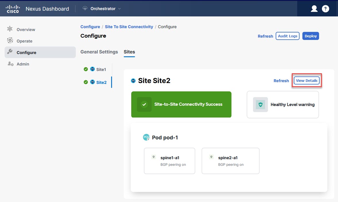 Figure 2. Configure > Fabric to Fabric Connectivity > Fabric > View Details
 -
In right sidebar’s Inter-Fabric Connectivity tab, disable the Multi-Fabric check box.
This disables EVPN peering between this fabric and other fabrics.
-
Click Deploy to deploy the changes to the fabric.
-
-
In the Cisco Nexus Dashboard Orchestrator GUI, disable the fabrics.
-
From the left navigation menu, select Fabrics.
-
In the main pane, change the State from
ManagedtoUnmanagedfor the fabric that you want to unmanage.
If the fabric is associated with one or more deployed templates, you will not be able to change its state to
Unmanageduntil you undeploy those templates, as described in the previous step.
-
-
Delete the fabric from Cisco Nexus Dashboard.
If you no longer want to manage this fabric or use it with any other applications, you can delete the fabric from the Cisco Nexus Dashboard as well.
The fabric must not be currently in use by any of the services that are installed in your Cisco Nexus Dashboard cluster.
-
In the top navigation bar, click the Home icon to return to the Cisco Nexus Dashboard GUI.
-
From the left navigation menu of the Cisco Nexus Dashboard GUI, select Operate > Fabrics.
-
Select one or more fabrics that you want to delete.
-
In the top right of the main pane, select Actions > Delete Fabric.
-
Provide the fabric’s sign-in information and click OK.
The fabric will be removed from the Cisco Nexus Dashboard.
-
Cross Launch to Fabric Controllers
Cisco Nexus Dashboard Orchestrator currently supports several configuration options for each type of fabrics. For many extra configuration options, you may need to sign in directly into the fabric’s controller.
You can cross-launch into the specific fabric controller’s GUI from the NDO’s Operate > Fabrics screen by selecting the actions (…) menu next to the fabric and clicking Open in user interface. Cross-launch works with out-of-band (OOB) management IP of the fabric.
If the same user is configured in Cisco Nexus Dashboard and the fabric, you will be signed in automatically into the fabric’s controller using the same log in information as the Cisco Nexus Dashboard user. For consistency, we recommend configuring remote authentication with common users across Cisco Nexus Dashboard and the fabrics.
Configuring Infra General Settings
Infra Configuration Dashboard
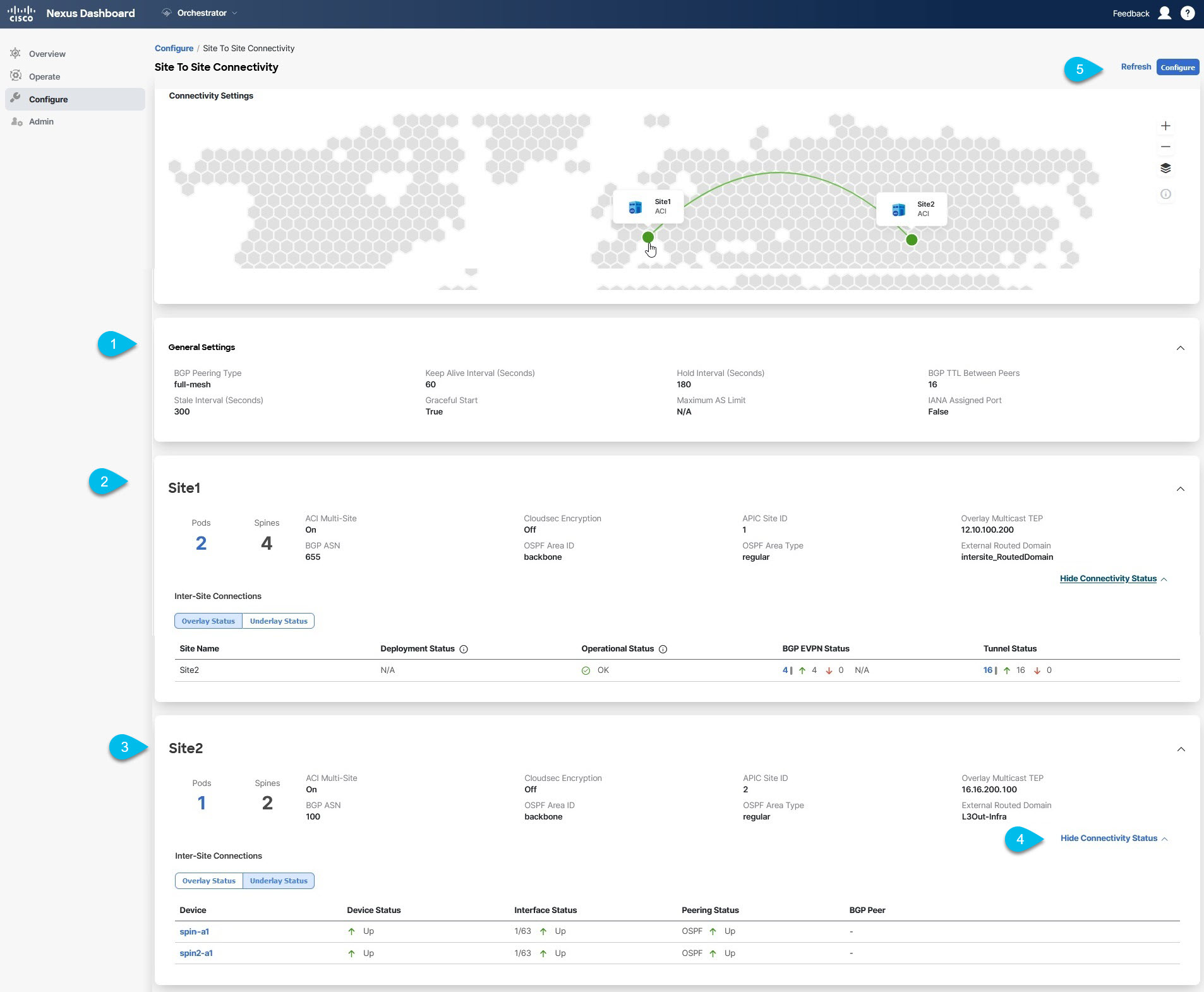
The Config > Fabric To Fabric Connectivity page displays a summary of all fabrics and inter-fabric connectivity in your Cisco Nexus Dashboard Orchestrator deployment and contains the following information:
-
The General Settings tile displays information about BGP peering type and its configuration.
This is described in detail in the next section.
-
The On-Premises tiles display information about every on-premises fabric that is part of your Multi-Fabric domain along with their number of Pods and spine switches, OSPF settings, and overlay IPs.
You can click the Pods tile that displays the number of Pods in the fabric to show information about the Overlay Unicast TEP addresses of each Pod.
This is described in detail in Configuring Infra for Cisco APIC Fabrics.
-
The Cloud tiles display information about every cloud fabric that is part of your Multi-Fabric domain along with their number of regions and basic fabric information.
This is described in detail in Configuring Infra for Cisco Cloud Network Controller Fabrics.
-
You can click Show Connectivity Status to display inter-fabric connectivity details for a specific fabric.
-
You can use the Configure button to navigate to the inter-fabric connectivity configuration, which is described in detail in the following sections.
The following sections describe the steps necessary to configure the general fabric Infra settings. Fabric-specific requirements and procedures are described in the following chapters based on the specific type of fabric that you are managing.
Before you proceed with Infra configuration, you must have configured and added the fabrics as described in previous sections.
In addition, any infrastructure changes such as adding and removing spine switches or spine node ID changes require a Cisco Nexus Dashboard Orchestrator fabric connectivity information refresh described in the Refreshing Fabric Connectivity Information as part of the general Infra configuration procedures.
Partial Mesh Inter-Fabric Connectivity
In addition to full mesh connectivity where you configure inter-fabric connectivity from every fabric managed by your Nexus Dashboard Orchestrator to every other fabric, this release also supports partial mesh configuration. In partial mesh configuration, you can manage fabrics in standalone mode with no inter-fabric connectivity to any other fabric or limit the inter-fabric configuration to only a subset of other fabrics in your Multi-Fabric domain.
Prior to Nexus Dashboard Orchestrator, Release 3.6(1), you could stretch templates between fabrics and refer to policies from other templates, which were deployed to other fabrics, even if the inter-fabric connectivity between those fabrics was not configured, resulting in intended traffic flow between the fabrics to not work.
Beginning with release 3.6(1), the Orchestrator will allow you to stretch template and remote reference policies from other templates (deployed on other fabrics) between two or more fabrics only if the inter-fabric connectivity between those fabrics is properly configured and deployed.
When configuring fabric infra for Cisco APIC and Cisco Cloud Network Controller fabrics as described in the following sections, for each fabric you can explicitly choose to which other fabrics infra connectivity will be established and provide that configuration information only.
Partial Mesh Connectivity Guidelines
When configuring partial mesh connectivity, consider the following guidelines:
-
Partial mesh connectivity is supported between two cloud fabrics or a cloud and on-premises fabric.
Full mesh connectivity is automatically established between all on-premises fabrics.
-
Partial mesh connectivity is supported using BGP-EVPN or BGP-IPv4 protocols.
Note however that stretching a template is allowed only for fabrics that are connected using BGP-EVPN protocol. If you are using BGP-IPv4 to connect two or more fabrics, any template assigned to any of those fabrics can be deployed to one fabric only.
Configuring Infra: General Settings
This section describes how to configure general Infra settings for all the fabrics.
Some of the following settings apply to all fabrics, while others are required for specific type of fabrics (for example, Cloud Network Controller fabrics). Ensure that you complete all the required configurations in infra general settings before proceeding to the fabric-local settings specific to each fabric.
-
Log in to the Cisco Nexus Dashboard Orchestrator GUI.
-
In the left navigation menu, select Configure > Fabric To Fabric Connectivity.
-
In the main pane, click Configure.
-
In the left sidebar, select General Settings.
-
Provide Control Plane Configuration.
-
Select the Control Plane Configuration tab.
-
Choose BGP Peering Type.
-
full-mesh-All border gateway switches in each fabric establishes peer connectivity with remote fabrics' border gateway switches.In
full-meshconfiguration, Cisco Nexus Dashboard Orchestrator uses the spine switches for ACI-managed fabrics and border gateways for NDFC-managed fabrics. -
route-reflector-The route-reflector option allows you to specify one or more control-plane nodes to which each fabric establishes MP-BGP EVPN sessions. The use of route-reflector nodes avoids creating MP-BGP EVPN full mesh adjacencies between all the fabrics that are managed by NDO.For ACI fabrics, the
route-reflectoroption is effective only for fabrics that are part of the same BGP ASN.
-
-
In the Keepalive Interval (Seconds) field, enter the keepalive interval seconds.
We recommend keeping the default value.
-
In the Hold Interval (Seconds) field, enter the hold interval seconds.
We recommend keeping the default value.
-
In the Stale Interval (Seconds) field, enter stale interval seconds.
We recommend keeping the default value.
-
Choose whether you want to turn on the Graceful Helper option.
-
Provide the Maximum AS Limit.
We recommend keeping the default value.
-
Provide the BGP TTL Between Peers.
We recommend keeping the default value.
-
Provide the OSPF Area ID.
If you do not have any Cloud Network Controller fabrics, this field will not be present in the UI.
This is OSPF area ID used by cloud fabrics for on-premises IPN peering.
-
(Optional) Enable IANA Assigned Port for CloudSec encryption.
By default, CloudSec uses a proprietary UDP port. This option allows you to configure CloudSec to use the official IANA-reserved port 8017 for CloudSec encryption between fabrics.
The IANA-reserved port is supported for Cisco APIC fabrics running release 5.2(4) or later.
To change this setting, CloudSec must be disabled on all fabrics. If you want to enable IANA reserved port, but already have CloudSec encryption that is enabled for one or more of your fabrics, disable CloudSec for all fabrics, enable IANA Reserve UDP Port option, then re-enable CloudSec for the required fabrics.
For detailed information and steps for configuring CloudSec, see the "CloudSec Encryption" chapter of the Nexus Dashboard Orchestrator Configuration Guide for ACI Fabrics.
-
-
Provide the IPN Devices information.
If you do not plan to configure inter-fabric connectivity between on-premises and cloud fabrics, you can skip this step.
When you configure inter-fabric underlay connectivity between on-premises and cloud fabrics as described in later sections, you must select an on-premises IPN device which establishes connectivity to the cloud CSRs. These IPN devices must first be defined here before they are available in the on-premises fabric configuration screen, which is described in more detail in Configuring Infra: On-Premises Fabric Settings.
-
Select the On Premises IPsec Devices tab.
-
Click +Add On-Premises IPsec Device.
-
Choose whether the device is Unmanaged or Managed and provide the device information.
This defines whether the device is directly managed by NDFC:
-
For Unmanaged IPN devices, simply provide the Name and the IP Address of the device.
The IP address that you provide will be used as the tunnel peer address from the cloud CSRs, not the IPN device’s management IP address.
-
For Managed IPN devices, choose the NDFC Fabric that contains the device and then the Device from that fabric.
Then choose the Interface on the device that is facing the Internet and provide the Next Hop IP address, which is the IP address of the gateway that is connecting to the Internet.
-
-
Click the check mark icon to save the device information.
-
Repeat this step for any additional IPN devices that you want to add.
-
-
Provide the External Devices information.
If you do not have any Cloud Network Controller fabrics, this tab will not be present in the UI.
If you do not have any Cloud Network Controller fabrics in your Multi-Fabric domain or you do not plan to configure connectivity between cloud fabrics and branch routers or other external devices, you can skip this step.
The following steps describe how to provide information about any branch routers or external devices to which you want to configure connectivity from your cloud fabrics.
-
Select the External Devices tab.
This tab will only be available if you have at least one cloud fabric in your Multi-Fabric domain.
-
Click Add External Device.
The Add External Device dialogue opens.
-
Provide the Name, IP Address, and BGP Autonomous System Number for the device.
The IP address that you provide will be used as the tunnel peer address from the Cloud Network Controller’s CSRs, not the device’s management IP address. The connectivity will be established over public Internet using IPsec.
-
Click the check mark icon to save the device information.
-
Repeat this step for any additional IPN devices that you want to add.
After you have added all the external devices, ensure to complete the next step to provide the IPsec tunnel subnet pools from with the internal IP addresses will be allocated for these tunnels.
-
-
Provide the IPsec Tunnel Subnet Pools information.
If you do not have any Cloud Network Controller fabrics, this tab will not be present in the UI.
There are two types of subnet pools that you can provide here:
-
External Subnet Pool-Used for connectivity between cloud fabric CSRs and other fabrics (cloud or on-premises).
These are large global subnet pools that are managed by Cisco Nexus Dashboard Orchestrator. The Orchestrator, creates smaller subnets from these pools and allocates them to fabrics to be used for inter-fabric IPsec tunnels and external connectivity IPsec tunnels.
You must provide at least one external subnet pool if you want to enable external connectivity from one or more of your cloud fabrics.
-
Fabric-Specific Subnet Pool-Used for connectivity between cloud fabric CSRs and external devices.
These subnets can be defined when the external connectivity IPsec tunnels must be in a specific range. For example, where a specific subnet is already being used to allocate IP addresses to the external router and you want to continue using those subnets for IPsec tunnels for NDO and cloud fabrics. These subnets are not managed by the Orchestrator and each subnet is assigned to a fabric in its entirety to be used locally for external connectivity IPsec tunnels.
If you do not provide any named subnet pools but still configure connectivity between cloud fabric’s CSRs and external devices, the external subnet pool will be used for IP allocation. .
The minimum mask length for both subnet pools is
/24.
To add one or more External Subnet Pools:
-
Select the IPsec Tunnel Subnet Pools tab.
-
In the External Subnet Pool area, click +Add IP Address to add one or more external subnet pools.
This subnet will be used to address the IPsec tunnel interfaces and loopbacks of the Cloud Routers that are used for on-premises connectivity, which you previously configured in the Cloud Network Controller for inter-fabric connectivity in earlier Cisco Nexus Dashboard Orchestrator releases.
The subnets must not overlap with other on-premises TEP pools, should not begin with
0.x.x.xor0.0.x.x, and should have a network mask between/16and/24, for example30.29.0.0/16. -
Click the check mark icon to save the subnet information.
-
Repeat these substeps for any additional subnet pools that you want to add.
-
To add one or more Fabric-Specific Subnet Pools:
-
Select the IsSec Tunnel Subnet Pools tab.
-
In the Fabric-Specific Subnet Pools area, click +Add IP Address to add one or more external subnet pools.
The Add Named Subnet Pool dialogue opens.
-
Provide the subnet Name.
You can use the subnet pool’s name to choose the pool from which to allocate the IP addresses later on.
-
Click +Add IP Address to add one or more subnet pools.
The subnets must have a network mask between
/16and/24`and not begin with `0.x.x.xor0.0.x.x, for example30.29.0.0/16. -
Click the check mark icon to save the subnet information.
Repeat the steps if you want to add multiple subnets to the same named subnet pool.
-
Click Save to save the named subnet pool.
-
Repeat these substeps for any additional named subnet pools that you want to add.
-
After you have configured general infra settings, you must still provide additional information for fabric-specific configurations based on the type of fabrics (ACI, Cloud Network Controller, or NDFC) you are managing. Follow the instructions described in the following sections to provide fabric-specific infra configurations.
Configuring Infra for Cisco APIC Fabrics
Refreshing Fabric Connectivity Information
Any infrastructure changes, such as adding and removing spines or changing spine node IDs, require a multi-fabric fabric connectivity fabric Refresh. This section describes how to pull up-to-date connectivity information directly from each fabric’s APIC.
-
Log in to the Cisco Nexus Dashboard Orchestrator GUI.
-
In the left navigation menu, select Config > Fabric To Fabric Connectivity.
-
In the top right of the main pane, click Configure.
-
In the left pane, under Fabrics, select a specific fabric.
-
In the main window, click the Refresh button to pull fabric information from the APIC.
-
(Optional) For on-premises fabrics, in the Confirmation dialog, check the box if you want to remove configuration for decommissioned spine switch nodes.
If you choose to enable this check box, all configuration info for any currently decommissioned spine switches will be removed from the database.
-
Finally, click Yes to confirm and load the connectivity information.
This discovers any new or removed spines and all fabric-related fabric connectivity will be reimported from the APIC.
Configuring Infra: On-Premises Fabric Settings
This section describes how to configure fabric-specific Infra settings for on-premises fabrics.
-
Log in to the Cisco Nexus Dashboard Orchestrator GUI.
-
In the left navigation menu, select Configure > Fabric To Fabric Connectivity.
-
In the top right of the main pane, click Configure.
-
In the left pane, under Fabrics, select a specific on-premises fabric.
-
Click View Details to load fabric settings.
Figure 4. Configure > Fabric to Fabric Connectivity > Fabric > View Details -
Provide the Inter-Fabric Connectivity information.
-
In the right <Fabric> Settings pane, enable the Multi-Fabric knob.
This defines whether the overlay connectivity is established between this fabric and other fabrics.
-
(Optional) Enable the CloudSec Encryption knob encryption for the fabric.
CloudSec Encryption provides inter-fabric traffic encryption. The Nexus Dashboard Orchestrator CloudSec Encryption for ACI Fabrics covers this feature in detail.
-
Specify the Overlay Multicast TEP.
This address is used for the inter-fabric L2 BUM and L3 multicast traffic. This IP address is deployed on all spine switches that are part of the same fabric, regardless of whether it is a single pod or multipod fabric.
This address should not be taken from the address space of the original fabric’s
InfraTEP pool or from the0.x.x.xrange. -
Specify the BGP Autonomous System Number.
-
(Optional) Specify the BGP Password.
-
Provide the OSPF Area ID.
The following settings are required if you are using OSPF protocol for underlay connectivity between the fabric and the IPN. If you plan to use BGP instead, you can skip this step. BGP underlay configuration is done at the port level, as described in Configuring Infra: Spine Switches.
-
Select the OSPF Area Type from the drop-down list.
The following settings are required if you are using OSPF protocol for underlay connectivity between the fabric and the IPN. If you plan to use BGP instead, you can skip this step. BGP underlay configuration is done at the port level, as described in Configuring Infra: Spine Switches.
The OSPF area type can be one of the following:
-
nssa -
regular
-
-
Configure OSPF policies for the fabric.
The following settings are required if you are using OSPF protocol for underlay connectivity between the fabric and the IPN. If you plan to use BGP instead, you can skip this step. BGP underlay configuration is done at the port level, as described in Configuring Infra: Spine Switches.
You can either click an existing policy (for example,
msc-ospf-policy-default) to modify it or click +Add Policy to add a new OSPF policy. Then in the Add/Update Policy window, specify the following:-
In the Policy Name field, enter the policy name.
-
In the Network Type field, choose either
broadcast,point-to-point, orunspecified.The default is
broadcast. -
In the Priority field, enter the priority number.
The default is
1. -
In the Cost of Interface field, enter the cost of interface.
The default is
0. -
From the Interface Controls drop-down list, choose one of the following:
-
advertise-subnet
-
bfd
-
mtu-ignore
-
passive-participation
-
-
In the Hello Interval (Seconds) field, enter the hello interval in seconds.
The default is
10. -
In the Dead Interval (Seconds) field, enter the dead interval in seconds.
The default is
40. -
In the Retransmit Interval (Seconds) field, enter the retransmit interval in seconds.
The default is
5. -
In the Transmit Delay (Seconds) field, enter the transmit delay in seconds.
The default is
1.
-
-
(Optional) From the External Routed Domain drop-down, select the domain that you want to use.
Choose an external router domain that you have created in the Cisco APIC GUI. For more information, see the Cisco APIC Layer 3 Networking Configuration Guide specific to your APIC release.
-
(Optional) Enable SDA Connectivity for the fabric.
If the fabric is connected to an SDA network, enable the SDA Connectivity knob and provide the External Routed Domain, VLAN Pool, and VRF Lite IP Pool Range information.
If you enable SDA connectivity for the fabric, you need to configure extra settings as described in Nexus Dashboard Orchestrator SD-Access and ACI Integration for ACI Fabrics.
-
(Optional) Enable SR-MPLS Connectivity for the fabric.
If the fabric is connected through an MPLS network, enable the SR-MPLS Connectivity knob and provide the Segment Routing global block (SRGB) range.
The Segment Routing Global Block (SRGB) is the range of label values that are reserved for Segment Routing (SR) in the Label Switching Database (LSD). These values are assigned as segment identifiers (SIDs) to SR-enabled nodes and have global significance throughout the domain.
The default range is
16000-23999.If you enable MPLS connectivity for the fabric, you need to configure extra settings as described in Nexus Dashboard Orchestrator Multi- Fabric and SR-MPLS L3Out Handoff for ACI Fabrics.
-
-
Configure inter-fabric connectivity between on-premises and cloud fabrics.
If you do not need to create inter-fabric connectivity between on-premises and cloud fabrics, for example if your deployment contains only cloud or only on-premises fabrics, skip this step.
When you configure underlay connectivity between on-premises and cloud fabrics, you must provide an IPN device IP address to which the Cloud Network Controller’s CSRs establish a tunnel and then configure the cloud fabric’s infra settings.
-
Click +Add IPN Device to specify an IPN device.
-
From the drop-down, select one of the IPN devices you defined previously.
The IPN devices must be already defined in the General Settings > IPN Devices list, as described in link:https://www-author3.cisco.com/c/en/us/td/docs/dcn/ndo/4x/articles-441/nexus-dashboard-orchestrator-aci-preparing-cisco-apic-fabrics-441.html#_configuring_infra_general_settings_2Configuring Infra: General Settings].
-
Configure inter-fabric connectivity for cloud fabrics.
Any previously configured connectivity from the cloud fabrics to this on-premises fabric will be displayed here, but any additional configuration must be done from the cloud fabric’s side as described in Configuring Infra for Cisco Cloud Network Controller Fabrics.
-
While you have configured all the required inter-fabric connectivity information, it has not been pushed to the fabrics yet. You must deploy the configuration as described in Deploying Infra Configuration.
Configuring Infra: Pod Settings
This section describes how to configure Pod-specific settings in each fabric.
-
Log in to the Cisco Nexus Dashboard Orchestrator GUI.
-
In the left navigation menu, select Configure > Fabric To Fabric Connectivity.
-
In the top right of the main pane, click Configure.
-
In the left pane, under Fabrics, select a specific fabric.
-
In the main window, select a Pod.
-
In the right Pod Properties pane, add the Overlay Unicast TEP for the Pod.
This IP address is deployed on all spine switches that are part of the same Pod and used for sourcing and receiving VXLAN encapsulated traffic for Layer2 and Layer3 unicast communication.
-
Click +Add TEP Pool to add an external routable TEP pool.
The external routable TEP pools are used to assign a set of IP addresses that are routable across the IPN to APIC nodes, spine switches, and border leaf nodes. This is required to enable Multi-Fabric architecture.
External TEP pools previously assigned to the fabric on APIC are automatically inherited by NDO and displayed in the GUI when the fabric is added to the Multi-Fabric domain.
-
Repeat the procedure for every Pod in the fabric.
Configuring Infra: Spine Switches
This section describes how to configure spine switches in each fabric for Cisco Multi-Fabric. When you configure the spine switches, you are effectively establishing the underlay connectivity between the fabrics in your Multi-Fabric domain by configuring connectivity between the spines in each fabric and the ISN.
Before Release 3.5(1), underlay connectivity was establishing using OSPF protocol. In this release however, you can choose to use OSPF, BGP (IPv4 only), or a mixture of protocols, with some fabrics using OSPF and some using BGP for inter-fabric underlay connectivity. We recommend configuring either OSPF or BGP and not both, however if you configure both protocols, BGP will take precedence and OSPF will not be installed in the route table.
-
Log in to the Cisco Nexus Dashboard Orchestrator GUI.
-
In the left navigation menu, select Config > Fabric To Fabric Connectivity.
-
In the top right of the main pane, click Configure.
-
In the left pane, under Fabrics, select the specific on-premises fabric.
-
In the main pane, select a spine switch within a pod.
-
In the right <Spine> Settings pane, click +Add Port.
-
In the Add Port window, provide the underlay connectivity information.
Any port that is already configured directly in APIC for IPN connectivity will be imported and shown in the list. For any new ports you want to configure from NDO, use the following the steps:
-
Provide general information:
-
In the Ethernet Port ID field, enter the port ID, for example
1/29.This is the interface which will be used to connect to the IPN.
-
In the IP Address field, enter the IP address/netmask.
The Orchestrator creates a subinterface with VLAN 4 with the specified IP ADDRESS under the specified PORT.
-
In the MTU field, enter the MTU. You can specify either
inherit, which would configure an MTU of 9150B, or choose a value between576and9216.MTU of the spine port should match MTU on IPN side.
-
-
-
Choose the underlay protocol.
-
Enable OSPF if you want to use OSPF protocol for underlay connectivity.
If you want to use BGP protocol for underlay connectivity instead, skip this part and provide the information that is required in the next substep.
-
Set OSPF to
Enabled.The OSPF settings become available.
-
From the OSPF Policy drop-down, select the OSPF policy for the switch that you have configured in Configuring Infra: On-Premises Fabric Settings.
OSPF settings in the OSPF policy you choose should match on IPN side.
-
For OSPF Authentication, you can pick either
noneor one of the following:-
MD5 -
Simple
-
-
Set BGP to
Disabled.
-
-
Enable BGP if you want to use BGP protocol for underlay connectivity.
If you’re using OSPF protocol for underlay connectivity and have already configured it in the previous substep, skip this part.
BGP IPv4 underlay is not supported in the following cases:
-
If your Multi-Fabric domain contains one or more Cloud Network Controller fabrics, in which case you must use the OSPF protocol for inter-fabric underlay connectivity for both On-Prem to On-Prem and On-Prem to cloud fabrics.
-
If you are using GOLF (Layer 3 EVPN services for fabric WAN) for WAN connectivity in any of your fabrics.
In the above cases, you must use OSPF in the Infra L3Out deployed on the spines.
-
Set OSPF to
Disabled.We recommend configuring either OSPF or BGP and not both, however if you configure both protocols, BGP will take precedence and OSPF routes will not be installed in the route table because only EBGP adjacencies with the ISN devices are supported.
-
Set BGP to
Enabled.The BGP settings become available.
-
In the Peer IP field, provide the IP address of this port’s BGP neighbor.
Only IPv4 IP addresses are supported for BGP underlay connectivity.
-
In the Peer AS Number field, provide the Autonomous System (AS) number of the BGP neighbor.
This release supports only EBGP adjacencies with the ISN devices.
-
In the BGP Password field, provide the BGP peer password.
-
Specify any additional options as required:
-
Bidirectional Forwarding Detection-Enables Bidirectional Forwarding Detection (BFD) protocol to detect faults on the physical link this port and the IPN device. -
Admin State-Sets the admin state on the port to enabled.
-
-
-
-
Repeat the procedure for every spine switch and port that connects to the IPN.
Configuring Infra for Cisco Cloud Network Controller Fabrics
Refreshing Cloud Fabric Connectivity Information
Any infrastructure changes, such as CSR and Region addition or removal, require a multi-fabric fabric connectivity fabric Refresh. This section describes how to pull up-to-date connectivity information directly from each fabric’s APIC.
-
Log in to the Cisco Nexus Dashboard Orchestrator GUI.
-
In the left navigation menu, select Config > Fabric To Fabric Connectivity.
-
In the top right of the main pane, click Configure.
-
In the left pane, under Fabrics, select a specific fabric.
-
In the main window, click the Refresh button to discover any new or changed CSRs and regions.
-
Finally, click Yes to confirm and load the connectivity information.
This discovers any new or removed CSRs and regions.
-
Click Deploy to propagate the cloud fabric changes to other fabrics that have connectivity to it.
After you Refresh a cloud fabric’s connectivity and CSRs or regions are added or removed, you must deploy infra configuration so other fabrics that have underlay connectivity to that cloud fabric get updated configuration.
Configuring Infra: Cloud Fabric Settings
This section describes how to configure fabric-specific Infra settings for Cloud Network Controller fabrics.
-
Log in to the Cisco Nexus Dashboard Orchestrator GUI.
-
In the left navigation menu, select Config > Fabric To Fabric Connectivity.
-
In the top right of the main pane, click Configure.
-
In the left pane, under Fabrics, select a specific cloud fabric.
-
Click View Details to load fabric settings.
Figure 5. Configure > Fabric to Fabric Connectivity > Fabric > View Details -
Provide the general Inter-Fabric Connectivity information.
-
In the right <Fabric> Settings pane, select the Inter-Fabric Connectivity tab.
-
Enable the Multi-Fabric knob.
This defines whether the overlay connectivity is established between this fabric and other fabrics.
The overlay configuration will not be pushed to fabrics which do not have the underlay inter-fabric connectivity that is established as described in the next step.
-
(Optional) Specify the BGP Password.
-
-
Provide fabric-specific Inter-Fabric Connectivity information.
-
In the right properties sidebar for the cloud fabric, click Add Fabric.
The Add Fabric window opens.
-
Under Connected to Fabric, click Select a Fabric and select the fabric (for example,
Fabric2) to which you want to establish connectivity from the fabric you are configuring (for example,Fabric1) .When you select the remote fabric, the Add Fabric window updates to reflect both directions of connectivity: Fabric1 > Fabric2 and Fabric2 > Fabric1.
-
In the Fabric1 > Fabric2 area, from the Connection Type drop-down, choose the type of connection between the fabrics.
The following options are available:
-
Public Internet-Connectivity between the two fabrics is established through the Internet.This type is supported between any two cloud fabrics or between a cloud fabric and an on-premises fabric.
-
Private Connection-Connectivity is established using a private connection between the two fabrics.This type is supported between a cloud fabric and an on-premises fabric.
-
Cloud Backbone-Connectivity is established using cloud backbone.This type is supported between two cloud fabrics of the same type, such as Azure-to-Azure or AWS-to-AWS.
If you have multiple types of fabrics (on-premises, AWS, and Azure), different pairs of fabric can use different connection type.
-
-
Choose the Protocol that you want to use for connectivity between these two fabrics.
If using BGP-EVPN connectivity, you can optionally enable IPSec and choose which version of the Internet Key Exchange (IKE) protocol to use: IKEv1 (
Version 1) or IKEv2 (Version 1) depending on your configuration.-
For
Public Internetconnectivity, IPsec is always enabled. -
For
Cloud Backboneconnectivity, IPsec is always disabled. -
For
Private Connection, you can choose to enable or disable IPsec.
If using BGP-IPv4 connectivity instead, you must provide an external VRF which will be used for route leaking configuration from the cloud fabric you are configuring.
After Fabric1 > Fabric2 connectivity information is provided, the Fabric2 > Fabric1 area will reflect the connectivity information in the oppofabric direction.
-
-
Click Save to save the inter-fabric connectivity configuration.
When you save connectivity information from
Fabric1toFabric2, the reverse connectivity is automatically created fromFabric2toFabric1, which you can see by selecting the other fabric and checking the Inter-fabric Connectivity information in the right sidebar. -
Repeat this step to add inter-fabric connectivity for other fabrics.
When you establish underlay connectivity from
Fabric1toFabric2, the reverse connectivity is done automatically for you.However, if you also want to establish inter-fabric connectivity from
Fabric1toFabric3, you must repeat this step for that fabric as well.
-
-
Provide External Connectivity information.
If you do not plan to configure connectivity to external fabrics or devices that are not managed by NDO, you can skip this step.
Detailed description of an external connectivity use case is available in the Configuring External Connectivity from Cloud CSRs Using Nexus Dashboard Orchestrator document.
-
In the right <Fabric> Settings pane, select the External Connectivity tab.
-
Click Add External Connection.
The Add External Connectivity dialog opens.
-
From the VRF drop-down, select the VRF you want to use for external connectivity.
This is the VRF which will be used to leak the cloud routes. The Regions section displays the cloud regions that contain the CSRs to which this configuration be applied.
-
From the Name drop-down in the External Devices section, select the external device.
This is the external device that you added in the General Settings > External Devices list during general infra configuration and must already be defined as described in Configuring Infra: General Settings.
-
From the Tunnel IKE Version drop-down, pick the IKE version that will be used to establish the IPsec tunnel between the cloud fabric’s CSRs and the external device.
-
(Optional) From the Tunnel Subnet Pool drop-down, choose one of the named subnet pools.
Named subnet pools are used to allocate IP addresses for IPsec tunnels between cloud fabric CSRs and external devices. If you do not provide any named subnet pools here, the external subnet pool will be used for IP allocation.
Providing a dedicated subnet pool for external device connectivity is useful for cases where a specific subnet is already being used to allocate IP addresses to the external router and you want to continue to use those subnets for IPsec tunnels for NDO and cloud fabrics.
If you want to provide a specific subnet pool for this connectivity, it must already be created as described in Configuring Infra: General Settings.
-
(Optional) In the Pre-Shared Key field, provide the custom keys that you want to use to establish the tunnel.
-
If necessary, repeat the previous substeps for any additional external devices you want to add for the same external connection (same VRF).
-
If necessary, repeat this step for any additional external connections (different VRFs).
There’s a one-to-one relationship for tunnel endpoints between CSRs and external devices, so while you can create extra external connectivity using different VRFs, you cannot create extra connectivity to the same external devices.
-
While you have configured all the required inter-fabric connectivity information, it has not been pushed to the fabrics yet. You must deploy the configuration as described in Deploying Infra Configuration.
Recovering from Cloud Network Controller Fabric Downtime
When Cloud Network Controller (formerly Cloud APIC) instance/VM goes down for any reason while still being managed by NDO, you may be unable to undeploy or delete any existing templates associated with that cloud fabric. In this case, attempting to forcefully unmanage the fabric in NDO can cause stale configuration and deployment errors even if the fabric recovers.
To recover from this:
-
Bring up the new Cloud Network Controller fabrics and reregister the cloud fabrics.
-
Log in to NDO.
-
Open the admin console.
-
Navigate to the Operate > Fabrics page.
-
From the action (…) menu next to the fabric you redeployed, choose Edit Fabric.
-
Check the "Reregister fabric" check box.
-
Provide the new fabric details.
You must provide the new public IP address of fabric and sign-in credentials.
-
Click *Save*to reregister the fabric.
When the connectivity status of the fabric shows
UP, the fabric IPs in NDO are also updated and the new fabrics are in 'managed' state. -
-
Undeploy the previously deployed templates for each schema.
-
Log in to NDO.
-
Navigate to Configure and select Tenant Template > Applications.
-
Click a schema with the deployed templates.
-
From the Actions menu next to the Template Properties, choose Undeploy Template and wait until the template is successfully undeployed.
-
-
Refresh the fabric’s infra configuration to ensure that the new Cisco Catalyst 8000V switches are added in NDO.
-
Navigate to Configure and select Fabric To Fabric Connectivity.
-
Click Configure at the top right of the screen.
-
Select the cloud fabric under the Fabrics panel and click Refresh.
-
Click Deploy on the top right of the screen and wait until all fabrics are successfully deployed.
-
-
Redeploy all templates associated with this Cloud Network Controller fabric.
-
Navigate to Configure > Tenant Templates under the Applications tab.
-
Click a schema with the templates undeployed earlier.
-
Click Deploy to Fabrics and wait until the template is deployed.
-
Deploying Infra Configuration for ACI Fabrics
Deploying Infra Configuration
This section describes how to deploy the Infra configuration to each APIC fabric.
-
In the top right of the main pane, click Deploy and choose the appropriate option to deploy the configuration.
If you have configured only on-premises or only cloud fabrics, simply click Deploy to deploy the Infra configuration.
However, if you have both, on-premises and cloud fabric, the following additional options may be available:
-
Deploy & Download IPN Device Config files: Pushes the configuration to both the on-premises APIC fabric and the Cloud Network Controller fabric and enables the end-to-end interconnect between the on-premises and the cloud fabrics.
In addition, this option downloads a zip file that contains configuration information that you will use to enable connectivity from the IPN devices to Cisco Cloud Services Router (CSR). A followup screen appears that allows you to select all or some of the configuration files to download.
-
Deploy & Download External Device Config files: Pushes the configuration to both the Cloud Network Controller fabrics and enables the end-to-end interconnect between the cloud fabrics and external devices.
In addition, this option downloads a zip file that contains configuration information that you will use to enable connectivity from external devices to the Cisco Cloud Services Router (CSR) deployed in your cloud fabrics. A followup screen appears that allows you to select all or some of the configuration files to download.
-
Download IPN Device Config files only: Downloads a zip file that contains configuration information that you will use to enable connectivity from the IPN devices to Cisco Cloud Services Router (CSR) without deploying the configuration.
-
Download External Device Config files only: Downloads a zip file that contains configuration information that you will use to enable connectivity from external devices to Cisco Cloud Services Router (CSR) without deploying the configuration.
-
-
In the confirmation window, click Yes.
The
Deployment started, refer to left menu for individual fabric deployment statusmessage will indicate that Infra configuration deployment began and you can verify each fabric’s progress by the icon displayed next to the fabric’s name in the left pane.
The Infra overlay and underlay configuration settings are now deployed to all fabrics' controllers and cloud CSRs. The last remaining step is to configure your IPN devices with the tunnels for cloud CSRs as descrbied in Refreshing Fabric Connectivity Information.
Enabling Connectivity Between On-Premises and Cloud Fabrics
If you have only on-premises or only cloud fabrics, you can skip this section.
This section describes how to enable connectivity between on-premises APIC fabrics and Cloud Network Controller fabrics.
By default, the Cisco Cloud Network Controller will deploy a pair of redundant Cisco Cloud Services Router 1000vs. The procedures in this section creates two tunnels, one IPsec tunnel from the on-premises IPsec device to each of these Cisco Cloud Services Router 1000vs. If you have multiple on-premises IPsec devices, you will need to configure the same tunnels to the CSRs on each of the on-premises devices.
The following information provides commands for Cisco Cloud Services Router 1000v as your on-premises IPsec termination device. Use similar commands if you are using a different device or platform.
-
Gather the necessary information that you will need to enable connectivity between the CSRs deployed in the cloud fabric and the on-premises IPsec termination device.
You can get the required configuration details using either the Deploy & Download IPN Device config files or the Download IPN Device config files only option in Nexus Dashboard Orchestrator as part of the procedures provided in Deploying Infra Configuration.
-
Log into the on-premises IPsec device.
-
Configure the tunnel for the first CSR.
Details for the first CSR are available in the configuration files for the ISN devices you downloaded from the Nexus Dashboard Orchestrator, but the following fields describe the important values for your specific deployment:
-
<first-csr-tunnel-ID>-unique tunnel ID that you assign to this tunnel.
-
<first-csr-ip-address>-public IP address of the third network interface of the first CSR.
The destination of the tunnel depends on the type of underlay connectivity:
-
The destination of the tunnel is the public IP of the cloud router interface if the underlay is via public internet
-
The destination of the tunnel is the private IP of the cloud router interface if the underlay is via private connectivity, such as DX on AWS or ER on Azure
-
-
<first-csr-preshared-key>-preshared key of the first CSR.
-
<onprem-device-interface>-interface that is used for connecting to the Cisco Cloud Services Router 1000v deployed in Amazon Web Services.
-
<onprem-device-ip-address>-IP address for the <interface> interface that is used for connecting to the Cisco Cloud Services Router 1000v deployed in Amazon Web Services.
-
<peer-tunnel-for-onprem-IPsec-to-first-CSR>-peer tunnel IP address for the on-premises IPsec device to the first cloud CSR.
-
<process-id>-OSPF process ID.
-
<area-id>-OSPF area ID.
The following example shows inter-fabric connectivity configuration using the IKEv2 protocol supported starting with Nexus Dashboard Orchestrator, Release 3.3(1) and Cloud Network Controller, Release 5.2(1). If you are using IKEv1, the IPN configuration file you downloaded form NDO may look slightly differently, but the principle remains the same.
+
crypto ikev2 proposal ikev2-proposal-default
    encryption aes-cbc-256 aes-cbc-192 aes-cbc-128
    integrity sha512 sha384 sha256 sha1
    group 24 21 20 19 16 15 14 2
exit

crypto ikev2 policy ikev2-policy-default
    proposal ikev2-proposal-default
exit

crypto ikev2 keyring key-ikev2-infra:overlay-1-__<first-csr-tunnel-id>__
    peer peer-ikev2-keyring
        address __<first-csr-ip-address>__
        pre-shared-key __<first-csr-preshared-key>__
    exit
exit

crypto ikev2 profile ikev2-infra:overlay-1-__<first-csr-tunnel-id>__
    match address local interface __<onprem-device-interface>__
    match identity remote address __<first-csr-ip-address>__ 255.255.255.255
    identity local address __<onprem-device-ip-address>__
    authentication remote pre-share
    authentication local pre-share
    keyring local key-ikev2-infra:overlay-1-__<first-csr-tunnel-id>__
    lifetime 3600
    dpd 10 5 on-demand
exit

crypto ipsec transform-set infra:overlay-1-__<first-csr-tunnel-id>__ esp-gcm 256
    mode tunnel
exit

crypto ipsec profile infra:overlay-1-__<first-csr-tunnel-id>__
    set pfs group14
    set ikev2-profile ikev2-infra:overlay-1-__<first-csr-tunnel-id>__
    set transform-set infra:overlay-1-__<first-csr-tunnel-id>__
exit

interface tunnel 2001
    ip address <peer-tunnel-for-onprem-IPsec-to-first-CSR> 255.255.255.252
    ip virtual-reassembly
    tunnel source __<onprem-device-interface>__
    tunnel destination __<first-csr-ip-address>__
    tunnel mode ipsec ipv4
    tunnel protection ipsec profile infra:overlay-1-__<first-csr-tunnel-id>__
    ip mtu 1400
    ip tcp adjust-mss 1400
    ip ospf __<process-id>__ area __<area-id>__
    no shut
exit
+
crypto ikev2 proposal ikev2-proposal-default encryption aes-cbc-256 aes-cbc-192 aes-cbc-128 integrity sha512 sha384 sha256 sha1 group 24 21 20 19 16 15 14 2 exit crypto ikev2 policy ikev2-policy-default proposal ikev2-proposal-default exit crypto ikev2 keyring key-ikev2-infra:overlay-1-2001 peer peer-ikev2-keyring address 52.12.232.0 pre-shared-key 1449047253219022866513892194096727146110 exit exit crypto ikev2 profile ikev2-infra:overlay-1-2001 ! Please change GigabitEthernet1 to the appropriate interface match address local interface GigabitEthernet1 match identity remote address 52.12.232.0 255.255.255.255 identity local address 128.107.72.62 authentication remote pre-share authentication local pre-share keyring local key-ikev2-infra:overlay-1-2001 lifetime 3600 dpd 10 5 on-demand exit crypto ipsec transform-set infra:overlay-1-2001 esp-gcm 256 mode tunnel exit crypto ipsec profile infra:overlay-1-2001 set pfs group14 set ikev2-profile ikev2-infra:overlay-1-2001 set transform-set infra:overlay-1-2001 exit ! These tunnel interfaces establish point-to-point connectivity between the on-prem device and the cloud Routers ! The destination of the tunnel depends on the type of underlay connectivity: ! 1) The destination of the tunnel is the public IP of the cloud Router interface if the underlay is via internet ! 2) The destination of the tunnel is the private IP of the cloud Router interface if the underlay is via private connectivity like DX on AWS or ER on Azure interface tunnel 2001 ip address 5.5.1.26 255.255.255.252 ip virtual-reassembly ! Please change GigabitEthernet1 to the appropriate interface tunnel source GigabitEthernet1 tunnel destination 52.12.232.0 tunnel mode ipsec ipv4 tunnel protection ipsec profile infra:overlay-1-2001 ip mtu 1400 ip tcp adjust-mss 1400 ! Please update process ID according with your configuration ip ospf 1 area 0.0.0.1 no shut exit -
-
Repeat the previous step for the 2nd and any additional CSRs that you need to configure.
-
Verify that the tunnels are up on your on-premises IPsec device.
Use the following command to display the status. If you do not see that both tunnels are shown as up, verify the information that you entered in the steps in this section to determine where you might have an issue. Do not proceed to the next section until you see that both tunnels are shown as up.
ISN_CSR# show ip interface brief | include Tunnel
Interface              IP-Address      OK? Method Status                Protocol
Tunnel1000             30.29.1.2         YES manual up                    *up*
Tunnel1001             30.29.1.4         YES manual up                    *up*
Upgrading Fabrics
Overview
This feature is supported for Cisco APIC fabrics only. It is not supported for Cisco Cloud Network Controller or Cisco NDFC fabrics.
When you deployed Cisco Multi-Fabric, each fabric’s APIC clusters and switch nodes software had to be managed individually at the fabric level. As the number of fabrics in your Multi-Fabric domain grew, the release life cycle and upgrades could become complicated as they had to be manually coordinated and managed for release and feature compatibility.
Cisco Nexus Dashboard Orchestrator provides a workflow that allows you to manage all fabrics' software upgrades from a single point eliminating the need for multiple fabric administrators to manually coordinate software upgrades and giving you insight into any potential issues that could affect the upgrades.
You can access the fabric upgrades screen by navigating to Admin > Software Management. The page contains four tabs, which are described in this and following sections.
The Overview tab displays information about the fabrics in your Multi-Fabric domain and the firmware versions that are deployed or ready to be deployed. The Fabrics Firmware service polls the fabrics every 5 minutes for new or changed data such as the latest status of any of the upgrade policies. You can manually trigger a Refresh by clicking the Refresh button in the upper right corner of the main pane.
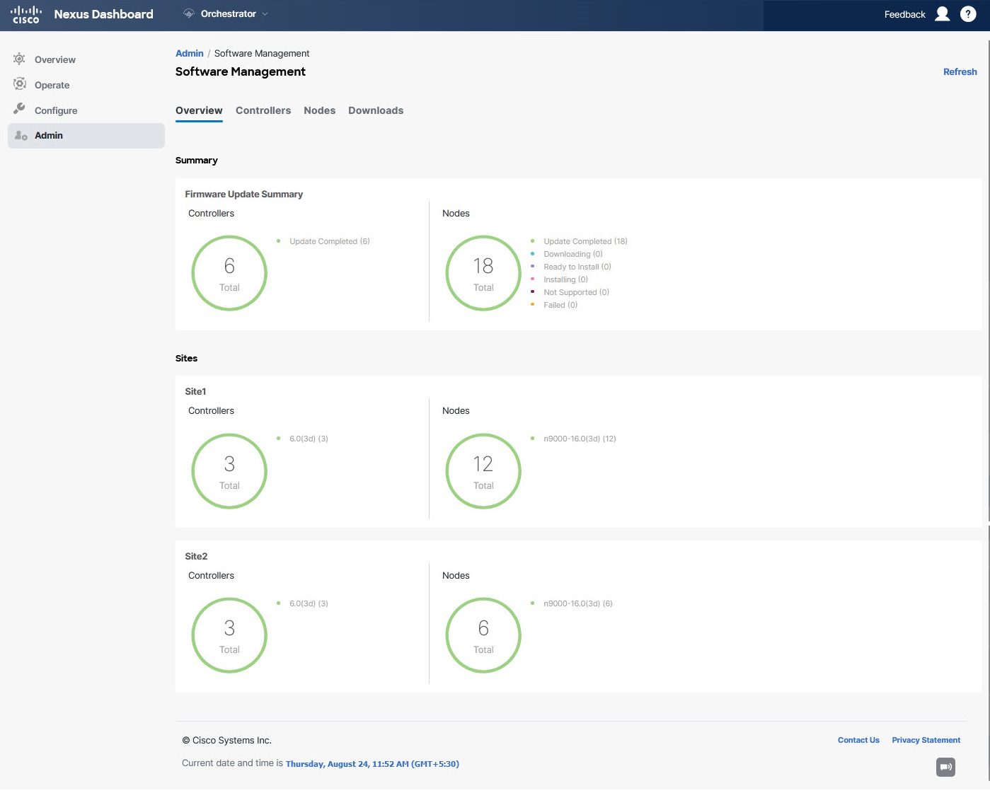
The page is divided into the following areas:
-
Firmware Update Summary-Provides overall summary of the firmware images that are present across all fabrics in your Multi-Fabric domain, including the Cisco APIC and the switch firmware.
For each type of image, the specific information includes the number of images in each state:
-
Completed-The image is currently deployed to the controllers or the switches. -
Downloading(for switch nodes only)-The image is being downloaded to the switch nodes. -
Ready to Install(for switch nodes only)-The image was successfully downloaded to the switch nodes and is ready to be installed. -
Installing-The images currently in the process of being deployed to the controllers or the switch nodes. -
Not Supported-The images that do not support remote firmware upgrades, such as releases before Release 4.2(5).
-
-
Fabric-specific information-Extra sections of the page display information about individual fabrics, which includes the version of the currently deployed software and the number of controllers or nodes.
Guidelines and Limitations
When performing fabric upgrades from the Cisco Nexus Dashboard Orchestrator, the following restrictions apply:
-
You must review and follow the guidelines, recommendations, and limitations specific to the Cisco APIC upgrade process described in the Upgrading and Downgrading the Cisco APIC and Switch Software of the Cisco APIC Installation, Upgrade, and Downgrade Guide.
-
Your Cisco Nexus Dashboard Orchestrator must be deployed in Cisco Nexus Dashboard.
The fabric upgrade feature is not available for NDO deployments in VMware ESX and you must follow the standard upgrade procedures that are described in Cisco APIC Installation, Upgrade, and Downgrade Guide
-
The fabrics must be running Cisco APIC, Release 4.2(5) or later.
Fabrics running earlier APIC releases will not be available for selection during the upgrade workflow. Follow the standard upgrade procedures described in Cisco APIC Installation, Upgrade, and Downgrade Guide.
-
We recommend coordinating the fabric upgrades with the fabric administrators managing those fabrics. You may need access to the controllers or switch nodes to troubleshoot any potential issues should they arise.
-
If a fabric switch node goes into an
inactivestate in the middle of the upgrade process, for example due to hardware or power failure, the process is unable to complete. You will not be able to remove or modify the node upgrade policy from NDO during this time as NDO is unable to differentiate whether the node went down or is simply in the middle of a reboot for the upgrade.To resolve this issue, you must manually decommission the inactive node from the APIC, at which point the NDO upgrade policy recognizes the change and return a
failedstatus. Then you can update the upgrade policy on the NDO to remove the switch and rerun the upgrade.
Downloading Controller and Switch Node Firmware to Fabrics
You must download the controller and switch software to all the fabric controllers in your fabrics before performing the upgrade. After you complete the following steps, you will be able to start the upgrade process later using the downloaded images.
-
Log in to your Cisco Nexus Dashboard Orchestrator.
-
Set up firmware download.
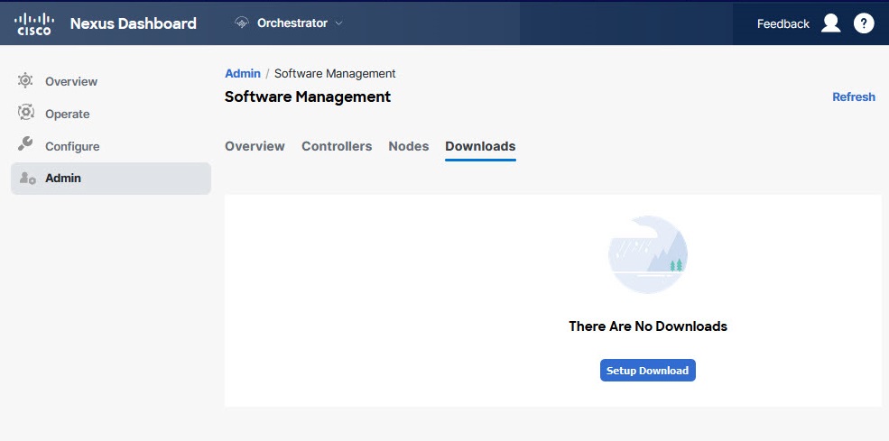 Figure 7. Fabric firmware update
-
From the left navigation pane, select Admin > Software Management.
-
In the main window, select the Downloads tab.
-
Click Setup Downloads tab.
If you have previously set up one or more downloads, click the Setup Downloads button in the top right of the main pane instead.
The Download Image to APIC screen opens.
-
-
Select the fabrics.
The image will be downloaded to the Cisco APICs of all the fabrics you select here.
-
Click Select Fabrics.
-
In the Select Fabrics window, check one or more fabrics and click Add and Close.
-
Click Next to proceed.
-
-
Provide the download details.
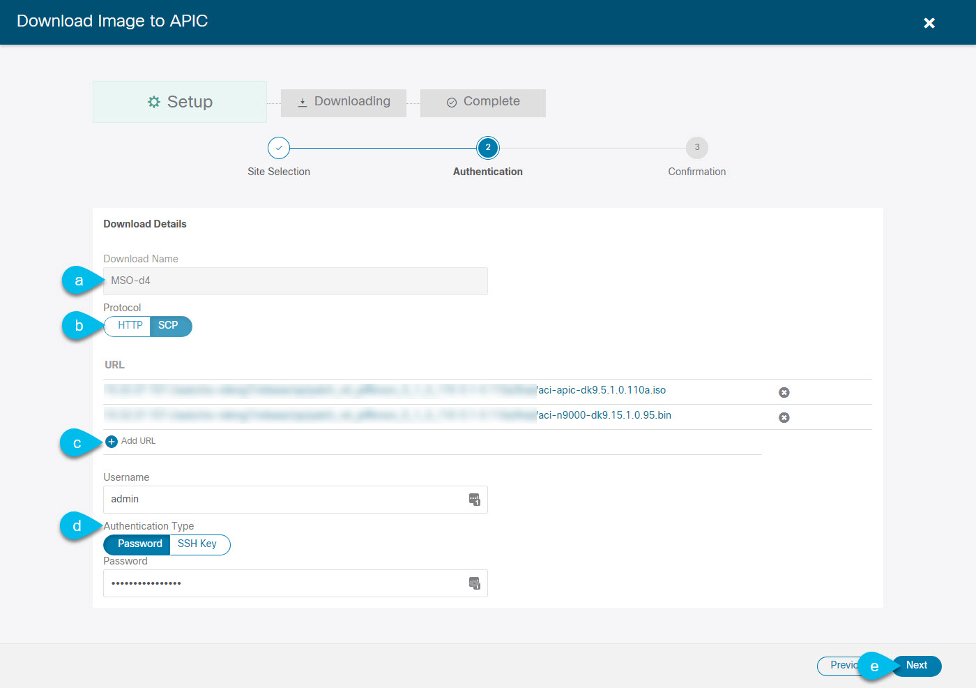 Figure 8. Details
-
Provide the Name.
You can provide a descriptive name for tracking the download.
-
Choose the protocol.
You can choose to download the image through
HTTPorSCP. -
Click + Add URL to provide location of one or more images.
You can provide both, the APIC and the switch firmware images.
-
If you selected SCP, provide the authentication information.
You must provide the sign-in Username, for example
admin.Then choose the Authentication Type:
-
For Password authentication, simply enter the password for the username you provided earlier.
-
For SSH Key authentication, you must enter the SSH Key and the SSH Key Passphrase.
-
-
Click Next to proceed.
-
-
In the confirmation screen, review the information and click Submit to proceed.
In the Downloading screen that opens, you can view the status of the image download.
You can also click the status, to see extra details about the progress.
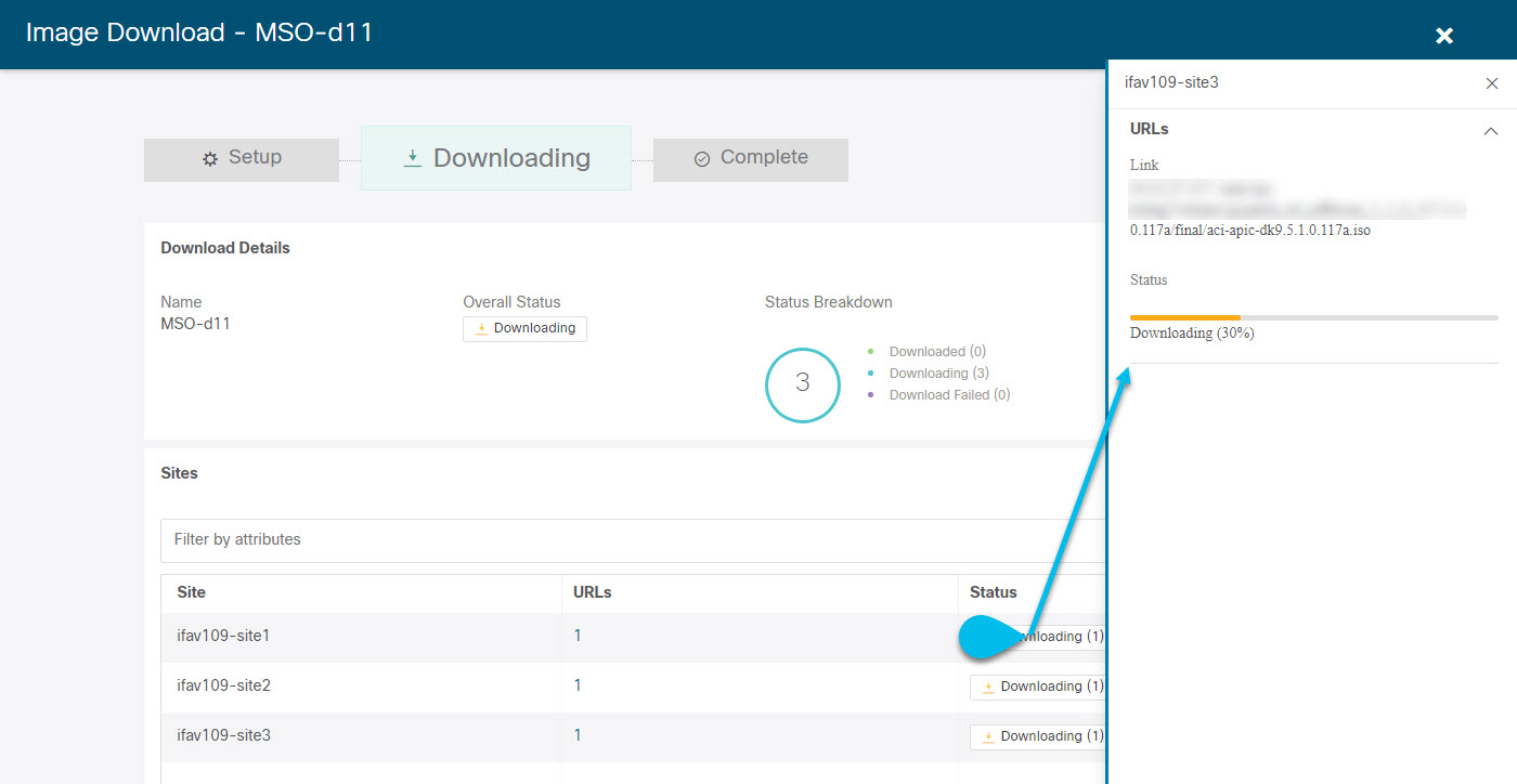
After all downloads complete, you will transition to the Completed screen. You do not have to wait at the Downloading screen, you can always navigate back to it from the Downloads tab by clicking the download name that you provided in a previous step.
The policy to copy APIC and switch firmware to APIC can be triggered from the Nexus Dashboard Orchestrator (NDO) GUI. However, the copied images in APIC cannot be deleted from the Nexus Dashboard Orchestrator GUI. Firmware delete can be initiated only from the APIC GUI, not from the Nexus Dashboard Orchestrator GUI.
Upgrading Controllers
This section describes how to set up a software upgrade for your fabrics' APIC clusters.
-
Log in to your Cisco Nexus Dashboard Orchestrator.
-
Set up APIC cluster upgrade.
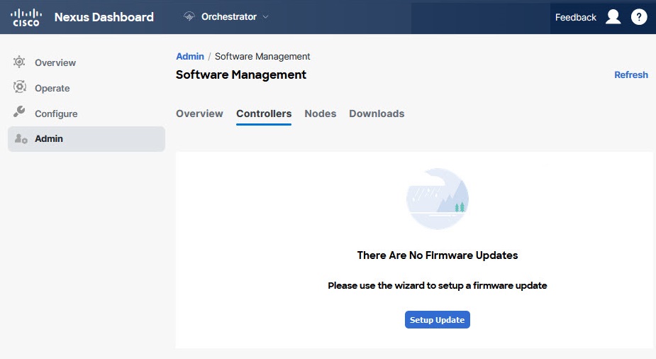 Figure 9. Upgrading Controllers
-
From the left navigation pane, select Admin > Software Management.
-
In the main window, select the Controllers tab.
-
Click Setup Update tab.
If you have previously set up one or more updates, click the Setup Update button in the top right of the main pane instead.
The Setup Fabric Firmware Update screen opens.
-
-
Provide the upgrade details.
-
Provide the Name.
This is the controller upgrade policy name that you will be able to use to track the upgrade progress at any time.
-
Click Select Fabrics.
The Select Fabrics window opens.
-
In the Select Fabrics window, check one or more fabrics and click Add and Close.
-
Click Next to proceed.
-
-
In the Version Selection screen, select the firmware version and click Next.
The firmware must be downloaded to the fabrics before it becomes available here. If the download you set up in previous section has completed successfully but the image is still not available here, close the Setup Fabric Firmware Update screen, navigate back to Admin > Software Management > Overview tab, and click the Refresh button to reload the latest information available for the fabrics; then restart the upgrade steps.
-
In the Validation screen, review the information, then click Next.
Ensure that there are no faults and review any additional information that may affect your upgrade:
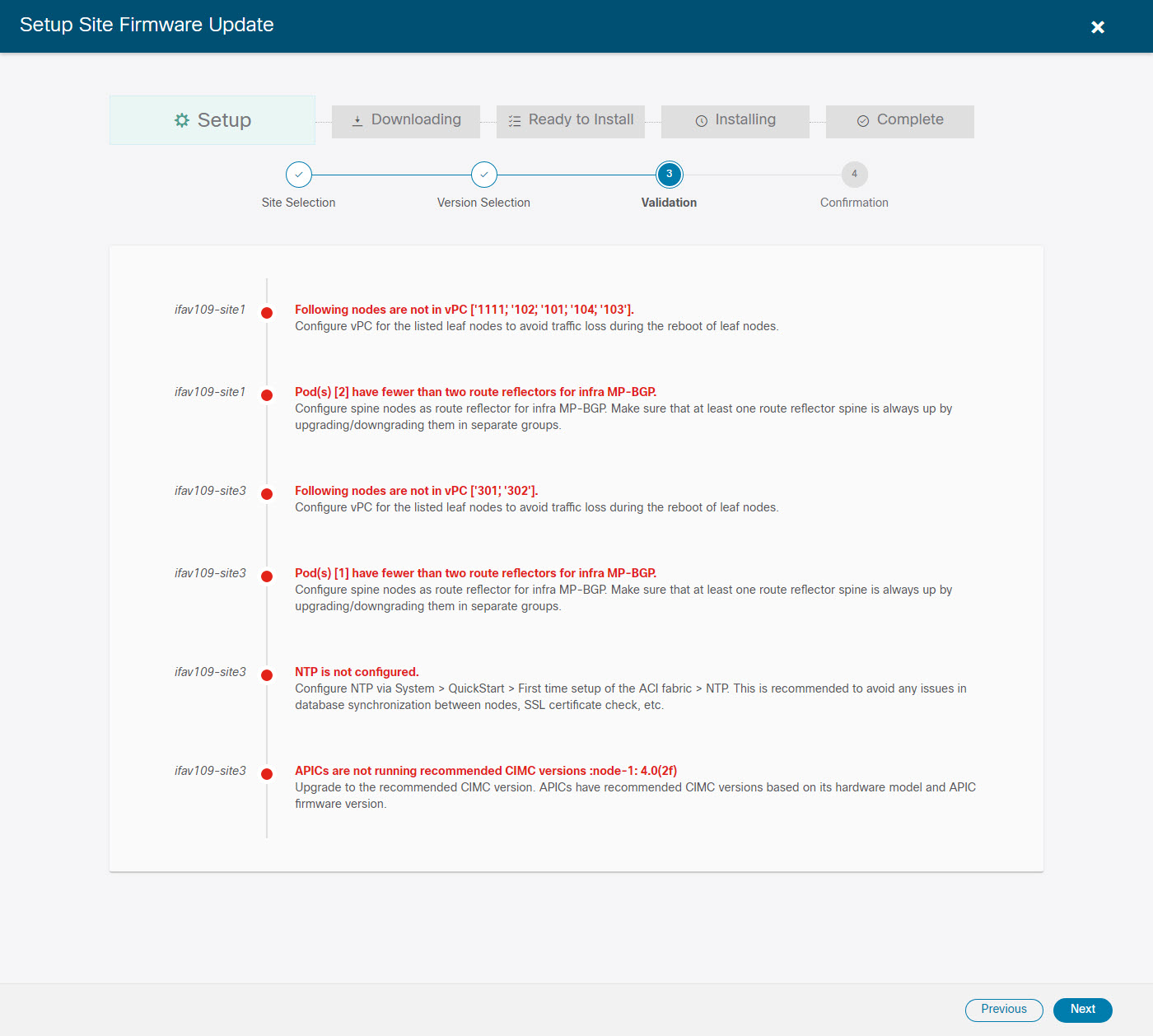
-
In the Confirmation screen, review the information and click Submit to start the upgrade.
-
In the Ready to Install screen, click Install to start the upgrade.
If NDO to fabric connectivity is lost during the upgrade process, the GUI displays the last known status of the upgrade before loss of connectivity. When connectivity is reestablished, the upgrade status will be refreshed. You can perform a manual Refresh after connectivity loss by clicking the Refresh button in the top right of the main pane.
Upgrading Nodes
This section describes how to set up a software upgrade for your fabrics' switch nodes.
-
Log in to your Cisco Nexus Dashboard Orchestrator.
-
Set up switch nodes upgrade.
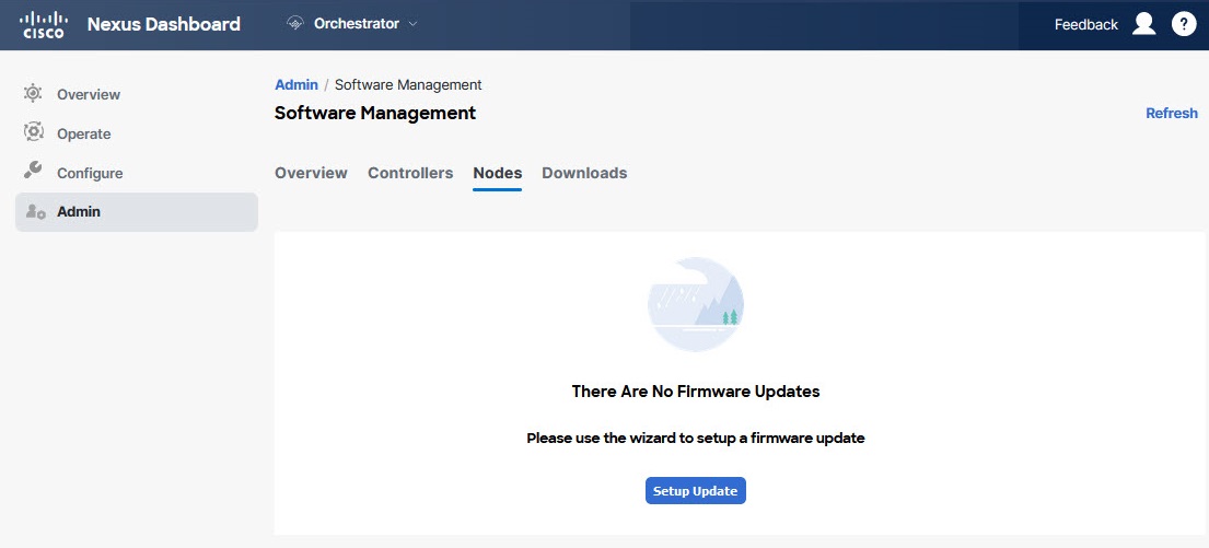 Figure 10. Switch nodes upgrade
-
From the left navigation pane, select AdminSoftware Management.
-
In the main window, select the Nodes tab.
-
Click Setup Update tab.
If you have previously set up one or more updates, click the Setup Update button in the top right of the main pane instead.
The Setup Node Firmware Update screen opens.
-
-
Provide the upgrade details.
-
Provide the Name.
This is the upgrade policy name that you are able to use to track the upgrade progress at any time.
-
Click Select Nodes.
The Select Nodes window opens.
-
Select a fabric, then select the switch nodes in that fabric and click Add and Close.
You can add switch nodes from a single fabric at a time. You repeat this step if you want to add switches from other fabrics. image::503324.jpg[,width=720]
-
Repeat the previous substep for nodes in other fabrics.
-
Click Next to proceed.
-
-
In the Version Selection screen, select the firmware version and click Next.
The firmware must be downloaded to the fabrics before it becomes available here. If the download you set up in previous section has completed successfully but the image is still not available here, close the Setup Fabric Firmware Update screen, navigate back to Admin > Software Management > Nodes tab, and click the Refresh button to reload the latest information available for the fabrics; then restart the upgrade steps.
-
In the Validation screen, ensure that there are no faults raised, then click Next.
Ensure that there are no faults and review any additional information that may affect your upgrade:
Fabrics running releases before Release 5.0(1) do not support node validation, so we recommend checking for any switch node faults in the fabric’s APIC before starting the upgrade from NDO.
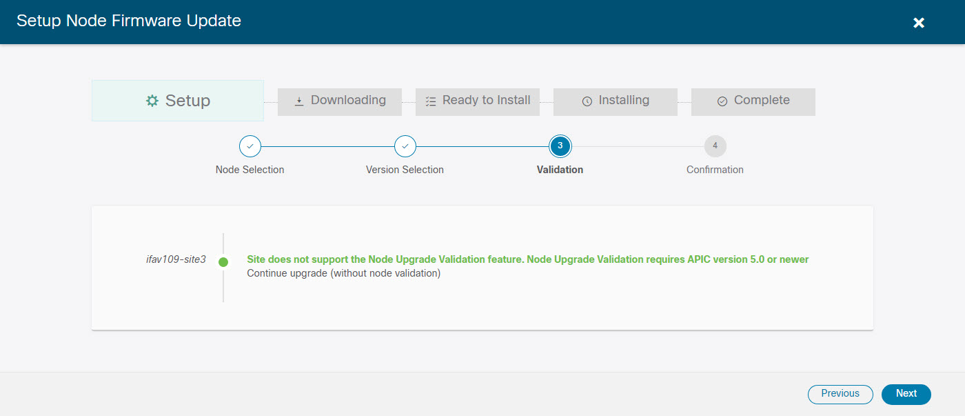
-
In the Confirmation screen, review the information and click Submit.
This triggers image to be predownloaded to all the nodes you have selected. After the download completes, the screen will transition to Ready to Install and you can proceed to the next step.
-
(Optional) Change Advanced Settings.
Review the guidelines, recommendations, and limitations for the Cisco APIC upgrade process described in the Upgrading and Downgrading the Cisco APIC and Switch Software of the Cisco APIC Installation, Upgrade, and Downgrade Guide before making changes to the advanced options.
In the Ready to Install screen, you can open the Advanced Settings menu for extra options:
-
Ignore Compatibility Check-By default, the option is set to
Noand compatibility check is enabled and verifies if an upgrade path from the currently running version of the system to a specified newer version is supported.If you choose to ignore the compatibility check feature, you run the risk of making an unsupported upgrade to your system, which could result in your system going to an unavailable state.
-
Graceful Check-By default, the option is set to
Noand the upgrade process will not put any of the switches into Graceful Insertion and Removal (GIR) mode before performing the upgrade.You can choose to enable this option to bring down the node gracefully (using GIR) while performing the upgrade so that the upgrade has reduced traffic loss.
-
Run Mode-By default, the option is set to
Continue on Failureand if a node upgrade fails, the process proceeds to the next node. Alternatively, you can set this option toPause on Failureto halt upgrade process if any one of the node upgrades fails.
-
-
Remove any nodes that are marked as
Failedfrom the upgrade.The upgrade cannot proceed if the upgrade policy contains one or more nodes that failed to download the firmware. You can mouse over the
Failedstatus for more information and reason for failure.To remove the nodes from the upgrade, click Edit Update Details link in the Ready to Install screen.
-
Click Install to start the upgrade.
If NDO to fabric connectivity is lost during the upgrade process, the GUI displays the last known status of the upgrade before loss of connectivity. When connectivity is reestablished, the upgrade status will be refreshed. You can perform a manual Refresh after connectivity loss by clicking the Refresh button in the top right of the main pane.
First Published: 2024-03-01
Last Modified: 2024-07-26
Americas Headquarters
Cisco Systems, Inc.
170 West Tasman Drive
San Jose, CA 95134-1706
USA
http://www.cisco.com
Tel: 408 526-4000
800 553-NETS (6387)
Fax: 408 527-0883