
System Settings
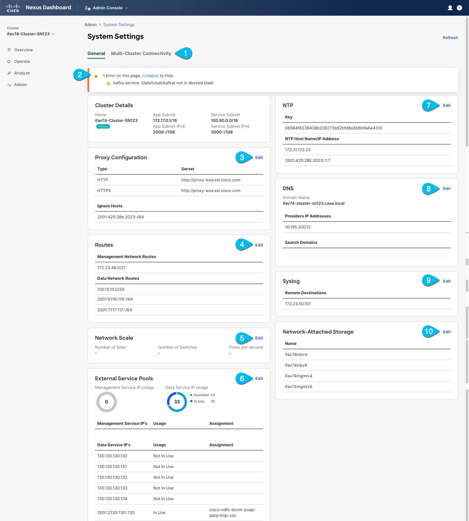
The System Settings GUI screen allows you to configure a number of options specific to the Nexus Dashboard cluster and its nodes. It will also display information about any issues that may be present in your Nexus Dashboard cluster.
-
The Multi-cluster Connectivity tab allows you to connect multiple clusters together for a single pane of glass view and administration of the clusters and their fabrics, services, and configurations.
For more information, see Multi-Cluster Connectivity.
-
The errors and warning tile will display the number of existing issues in your cluster. You can click Expand to see the full list of specific issues.
-
To configure a proxy for the Nexus Dashboard, click the Edit icon in the Proxy Configuration tile.
In certain deployment scenarios, such as with a combination of on-premises and cloud sites and the Nexus Dashboard cluster deployed inside a corporate network, you may have to access the Internet and the cloud sites through a proxy.

This release supports adding a single proxy server.
Note that Nexus Dashboard uses 2 main route tables — one for the Management network and one for the Data network — and by default, it will use the routing table of the originating IP address. In other words, Nexus Dashboard will attempt to reach the proxy from the routing table of the POD/Service that is trying to use the proxy.
For example, if you configure a proxy and establish Intersight connectivity from your Nexus Dashboard and then attempt to configure AppD integration from the Insights service running in the cluster, you may get an error stating that AppD host is not reachable. This happens because the proxy is only accessible from the management interface, so in such cases you also need to add a management network route for the proxy IP address, as described in "Management Network or Data Network routes" below.
To add a proxy server:
-
Click +Add Server in the proxy configuration window.
-
From the Type dropdown, select the type of traffic that you want to be proxied.
-
In the Server field, provide the full address for the proxy server including the port if required.
For example
http://proxy.company.com:80. -
If the server requires login credentials, provide the Username and Password.
-
(Optional) Click Add Ignore Host to provide any hosts that will ignore the proxy.
You can add one or more hosts with which the cluster will communicate directly bypassing the proxy.
-
-
To add one or more Management Network or Data Network routes, click the Edit icon in the Routes tile.
Here you can define static routes for the management or data interfaces. For example, adding
10.195.216.0/21as a Data Network route will cause all traffic destined to that subnet to transit out of the data network interface.-
To add a management network route, click Add Management Network Routes and provide the destination subnet.
-
To add a data network route, click Add Data Network Routes and provide the destination subnet.
-
-
To add one or more External Service Pools, click the Edit icon in the External Service Pools tile.
This allows you to provide persistent IP addresses for services that require to retain the same IP addresses even in case they are relocated to a different Nexus Dashboard node.
For detailed information and configuration steps, see Persistent IP Addresses.
-
To configure NTP settings, click the Edit icon in the NTP tile.
By default, the NTP server that you configured when deploying the Nexus Dashboard cluster is listed here.
You can provide additional NTP servers by clicking +Add NTP Server.
You can remove existing NTP server by clicking the Delete icon next to it. Keep in mind that at least one NTP server must be configured in your cluster.
-
To configure DNS settings, click the Edit icon in the DNS tile.
By default, the DNS server and search domain that you configured when deploying the Nexus Dashboard cluster are listed here.
You can provide additional DNS servers and search domains by clicking +Add a Provider or +Add a Search Domain respectively.
You can remove existing DNS server by clicking the Delete icon next to it.
-
To provide one or more
syslogservers to stream event logs to, click the Edit icon in the Syslog tile.In the Syslog dialog that opens, click +Add Remote Destinations to add a new server. Then provide the IP address, protocol, and port number for the server and choose whether you want to enable streaming to this syslog server at this time.
For more information, see History and Logs.
-
To configure Network-Attached Storage (NAS), click the Edit icon in the Network-Attached Storage tile.
Beginning with release 3.0(1), you can add a NAS server at the Nexus Dashboard level which can be utilized by the services running in your cluster.
This release supports only NFSv3 remote storage.
To add a NAS:
-
Click +Add Network-Attached Storage in the NAS configuration window.
-
Choose whether Nexus Dashboard has
Read OnlyorRead Writeaccess to this server. -
Provide the Name for the NAS server.
-
(Optional) Provide the Description.
-
Provide the IP address used to connect to the server.
-
Specify the Port used to establish the connection if it is different from the default port
2049. -
Provide the Export Path to a directory on the NAS server where information will be stored or read.
-
Specify the Alert Threshold.
-
Specify the storage Limit.
This limits the ammount of storage that can be requested on the server by Nexus Dashboard. You can provide the values in Mibibytes or Gibibytes, for example
300Mior10Gi. -
From the Allowed Apps dropdown, select which Nexus Dashboard services can access this storage.
-
Persistent IP Addresses
You can provide persistent IP addresses for services that require to retain the same IP addresses even in case they are relocated to a different Nexus Dashboard node.
Nexus Dashboard Insights requires some services (such as SNMP trap, syslog, and others) to stream data from the switches in your fabrics to the service. An IP address is configured on the switches for this purpose. Typically, if the IP address changes when the service is relocated, the service will reconfigure the new IP address on the switches.
In order to avoid this IP reconfiguration impact on the fabric switches, the service can request that the services IP addresses are preserved, in which case you will need to define a set of IP addresses which can be assigned to the service for this purpose.
If a service requires persistent IP addresses, you will not be able to enable that service in the Nexus Dashboard until enough IP addresses are defined as described below.
This feature is supported for Nexus Dashboard Insights with NDFC fabrics only. In addition, if you are using Layer 2 functionality only (IPs configured as part of the management and data subnets) and your Nexus Dashboard is deployed in VMware ESX, you must enable promiscuous mode for both management and data network interface portgroups, as described in https://kb.vmware.com/s/article/1004099.
Prior to Release 2.2(1), this feature was supported only for clusters where all nodes were part of the same Layer 3 network and the persistent IPs were defined as part of the node’s management or data networks. Here the application uses Layer 2 mechanisms like Gratuitous ARP or Neighbor Discovery to advertise the persistent IPs within it’s Layer 3 network.
Beginning with Release 2.2(1), the feature is supported even if you deploy the cluster nodes in different Layer 3 networks. In this case, the persistent IPs are advertised out of each node’s data links via BGP, which we refer to as "Layer 3 mode". The IPs must not overlap with any of the nodes' management or data subnets. If the persistent IPs are outside the data and management networks, this feature will operate in Layer 3 mode by default; if the IPs are part of those networks, the feature will operate in Layer 2 mode.
Persistent IP Guidelines and Limitations
When configuring persistent IPs for your services:
-
Ensure that you check the documentation for the services you plan to deploy as some services do not support this feature or require additional guidelines.
At this time, Persistent IPs are supported for Nexus Dashboard Insights and Nexus Dashboard Fabric Controller. You can find the service-specific documentation at the following links:
-
You can choose which mode you want to operate in as long as the following conditions apply:
-
If you choose to operate in Layer 2 mode, the nodes must be part of the same data and management networks.
-
If you choose to operate in Layer 3 mode, all nodes must have BGP configuration provided either during cluster deployment or after as described in Enabling BGP On All Nodes.
-
You can switch between the two modes, in which case the existing services of a particular mode must be completely deleted and you will need to configure new persistent IPs corresponding to the new mode.
-
-
If you configure one or more persistent IPs in Layer 3 mode and back up cluster configuration, the BGP settings required for this feature are not saved in the backup.
As such, you must ensure that you configure BGP for all cluster nodes before restoring any cluster configuration that contains Layer 3 persistent IPs in that cluster. If BGP is not configured prior to the configuration import, the import will fail.
Enabling BGP On All Nodes
If you want to operate in Layer 3 mode, you must enable and configure BGP for all nodes in your cluster. If you already configured BGP for each node during cluster deployment or if you want to operate in Layer 2 mode instead, you can skip this section and simply provide one or more persistent IPs from the nodes' management and data subnets, as described in Configuring Persistent IPs. Note that if you choose to operate in Layer 2 mode, all nodes must be part of the same Layer 3 network. If you choose to operate in Layer 3 mode, at least one BGP peer must configured on all cluster nodes to advertise the IPv4 or the IPv6 persistent IP addresses as described in this section.
-
Ensure that the uplink peer routers are capable of exchanging the advertised persistent IPs across the Layer 3 networks of the cluster nodes.
-
When a service requests a persistent IP address, the route advertised from the data links via BGP on the node where the service is running is maintained throughout the lifecycle of the service.
To configure BGP on the nodes:
-
Navigate to your Nexus Dashboard’s Admin Console.
-
From the left navigation menu, select System Resources > Nodes.
-
Click the Actions (…) menu next to one of the nodes and choose Edit.
-
In the Edit Node screen, turn on Enable BGP.
-
In the ASN field, provide the autonomous system number for the node.
-
Click +Add IPv4 BGP Peer or +Add IPv6 BGP Peer to provide peer IP address information.
-
In the Peer Address field, provide the IPv4 or IPv6 address of the peer router for this node.
Multi-hop BGP peering is not supported, so you must ensure that the Peer Address is part of the node’s data subnet.
-
In the Peer ASN field, provide the autonomous system number of the peer router.
Only EBGP is supported, so you must ensure that the node ASN and Peer ASN are different.
-
Click Save to save the changes.
-
-
Repeat these steps for every node in the cluster.
Every node in the cluster must have BGP configured.
You can configure the same ASN for all nodes or a different ASN per node
Configuring Persistent IPs
-
For all persistent IPs, you must use either the Layer 2 or Layer 3 approach; a combination of the two is not supported.
If all nodes are in the same Layer 3 network, you can choose to use either the Layer 2 mode or Layer 3 mode for this feature. The two modes are described in Persistent IP Addresses.
If the nodes are in different Layer 3 networks, you must configure the persistent IPs such that they don’t overlap with either the management or the data subnets of the nodes.
-
If the nodes in your cluster belong to different Layer 3 networks, you must have BGP enabled and configured as described in Enabling BGP On All Nodes.
-
There may be a momentary traffic interruption while a service using a persistent IP is relocated to a different node.
The interruption duration depends on the following factors:
-
Time to detect the node failure
-
Time for the service to get rescheduled to a different node
-
Time for the service’s external IP to get advertised from the scheduled node via GARP (IPv4) or neighbor discovery (IPv6) in case of Layer 2 mode
-
Time for the service’s external IP to get advertised from the scheduled node via BGP in case of layer 3 mode
-
To provide one or more persistent IP addresses:
-
Navigate to your Nexus Dashboard’s Admin Console.
-
From the left navigation menu, select Admin > System Settings.
-
In the External Service Pools tile, click the Edit icon.
-
In the External Service Pools screen that opens, click +Add IP Address to add one or more IP addresses for the management or data networks.
When editing persistent IPs, the following rules apply:
-
If all nodes in your cluster are part of the same Layer 3 network, you can choose one of the following:
-
Layer 2 mode, in which case the IP addresses you add for management services must be part of the management subnet and the IP addresses for data services must be part of the data subnet.
-
Layer 3 mode, in which case the IP addresses you add must not overlap with the management or the data subnets of the nodes. In this case, adding IPs under "Management Service IPs" is not supported and you must add the IPs to the "Data Service IPs" category in the GUI.
-
-
You must provide either IPv4 or IPv6 IP addresses, you cannot give both.
-
You must add individual IP addresses one by one without any prefix; adding a range of IP addresses is not supported.
-
You can remove any previously defined IPs, but you will not be able to remove any IPs that are currently in use by one or more services.
-
Multi-Cluster Connectivity
You can establish connectivity between multiple Nexus Dashboard clusters for ease of access to all the clusters, as well as access to any of the fabrics and services running on any of the connected clusters.
When you add a second cluster, a group of clusters is formed. The cluster from which you create the group becomes the "primary" cluster with a number of unique characteristics that do not apply to other clusters in the group:
-
You must use the primary cluster to connect all additional clusters.
-
You must use the primary cluster to remove any of the clusters from the group.
-
When upgrading Nexus Dashboard, you must upgrade the primary cluster before any other clusters in the group.
Establishing multi-cluster connectivity does not create any single databases with information from all clusters in the group. Every cluster continues to maintain its own configuration databases, while simultaneously being able to function as a proxy for all other clusters in the group regardless of which cluster an action or request is originated from or destined to.
Guidelines and Limitations
The following guidelines apply when configuring multi-cluster connectivity:
-
This release supports multi-cluster connectivity between clusters deployed using physical or virtual (ESX) form factors only.
In other words, you can join physical Nexus Dashboard clusters with virtual (ESX) clusters, but virtual (KVM) or cloud clusters do not support this feature.
-
For supported scale limits, such as number of clusters that can be connected together and number of fabrics across all clusters, see the Nexus Dashboard Release Notes for your release.
-
Connectivity (HTTPS) must be established between the management interfaces of all the nodes of all the clusters, which will be connected via multi-cluster connectivity.
-
The names of the fabrics onboarded in the clusters that you plan to connect together must be unique across those clusters.
Duplicate fabric names across different clusters may result in DNS resolution failures.
-
The primary cluster, which you use to establish multi-cluster connectivity, must be running the same or a later release of Nexus Dashboard than any other cluster in the group.
In other words, you cannot connect a Nexus Dashboard cluster running release 2.3.1 from a primary cluster that is running release 3.0.1.
-
If you are upgrading multiple clusters that are connected together, you must upgrade the primary cluster first.
-
From any cluster in the connected clusters group, you can view other clusters only if they are running the same or earlier version of Nexus Dashboard.
In other words, if
cluster1is running release 2.3.1 andcluster2is running release 2.2.1, you can viewcluster2fromcluster1but not vice versa. -
Multi-Cluster connectivity is supported for remote users only.
If you connect multiple clusters, but then login to one of the clusters as a local
adminuser, you will only be able to view and manage the local cluster into which you logged in.To view and manage all clusters in the group, you must login as a remote user that is configured on all clusters.
-
Nexus Dashboard Insights service in each cluster can view fabric groups from other Insights services across any cluster in the group.
However, when creating fabric groups, each Insights service can add fabrics which are onboarded in the same cluster where the service is installed only.
-
Nexus Dashboard Orchestrator service supports managing only fabrics which are onboarded in the same cluster where the service is installed.
Connecting Multiple Clusters
-
You must have familiarized yourself with the information provided in the Guidelines and Limitations section.
-
You must have set up remote authentication and users on all clusters which you plan to connect.
Multi-Cluster connectivity is supported for remote users only, so you must configure the same remote user with
adminprivieleges for all clusters. For additional details, see Remote Authentication.
To connect another cluster:
-
Log in to the Nexus Dashboard GUI of the cluster which you want to designate as the primary.
-
Add second cluster.
-
From the main navigation menu, select Admin > System Settings.
-
In the main pane, select the Multi-Cluster Connectivity tab.
-
Click Connect Cluster.
-
-
Provide cluster information.
-
In the information fields, provide the hostname or IP address and the authentication information for the cluster you are adding.
You only need to provide the management IP address of one of the nodes in the target cluster. Other nodes' information will be automatically synced after connectivity is established.
-
Then click Save.
The user you provide must have administrative rights on the cluster you are adding. The user credentials are used once when you are first establishing connectivity to the additional cluster. After initial connectivity is established, all subsequent communication is done through secure keys. The secure keys are provisioned to each cluster while adding it to the group.
The cluster you are adding must not be part of an already existing group of clusters.
-
-
Repeat the procedure for any additional Nexus Dashboard cluster which you want to add to the group.
After multiple clusters are added to the group, you can see their status in the Cluster Configuration > Multi-Cluster Connectivity page.
Note that while you can view and manage any cluster from any other cluster as long as they are part of the same multi-cluster group, you can only add and remove clusters from the group when viewing the
primarycluster.
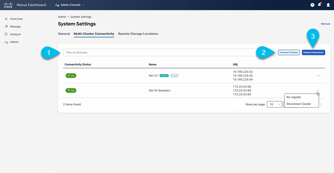
The Multi-Cluster Connectivity page displays all clusters that are part of the multi-cluster group. The Connect Cluster button is shown only when viewing the primary cluster. To modify the cluster group, you need to navigate to the primary cluster, at which point the Connect Cluster button becomes available:
-
The Cluster: <name> dropdown in the main navigation menu shows the cluster you are currently viewing.
You can select a different cluster from this dropdown, which opens a new window allowing you to navigate to another cluster in the same group.
While the 2.x releases of Nexus Dashboard allowed you to view and manage any cluster from any other cluster as long as they were part of the same multi-cluster group, relese 3.0.1 changed this behavior. You can now easily navigate between clusters by picking a specific cluster from the Cluster dropdown in the main navigation pane, but you cannot manage or configure another cluster directly from the one where you are logged in.
-
The
Primarylabel indicates the group’s primary cluster.You must be viewing this cluster to make any changes to the cluster group, such as adding or removing clusters.
-
The
Locallabel indicates the cluster you logged into.This is the cluster whose address is displayed in the browser’s URL field. If you navigate to a different cluster as mentioned above, the browser URL and the
Locallabel will not change. -
Connectivity Status: Shows the status of the uplink to the cluster. -
URLshows the list of IP addresses of the cluster. -
The Actions (
…) menu for each cluster allows you to Re-Register and Disconnect Cluster
-
-
The Connect Cluster button allows you to add a new cluster.
-
The Delete Federation button is to be used only for recovering failure scenarios that may happen in a federation. The action that’s taken when clicking Delete Federation varies depending on whether you’re logged in on a primary or a secondary cluster. For more information on the Delete Federation option, see Deleting the Federation.
Disconnecting Clusters
To disconnect a cluster from an existing group:
-
Log in to the Nexus Dashboard GUI of the primary cluster.
Adding and removing clusters from the group must be done from the primary cluster.
-
From the main navigation menu, select Admin > System Settings.
-
In the main pane, select the Multi-Cluster Connectivity tab.
-
From the Actions (
…) menu for the cluster you want to remove, select Disconnect Cluster -
If the cluster status is still shown as
Upat this time, you will be given an option to forcefully remove the member. This option should be used only if previous removal attempts were unsuccessful, and does not guarantee that all federation info stored remotely on the secondary will be cleaned up.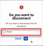 Disconnecting Clusters
 -
In the confirmation window, click Ok.
If you want to delete the federation from the primary cluster, after disconnecting all the secondary clusters from the primary cluster, use the Delete Federation button to remove the federation from the primary cluster. See Deleting the Federation for more information.
Deleting the Federation
In order to delete the federation from Primary cluster use Delete Federation button only after disconnecting all the secondary clusters from the primary cluster.
To delete the federation:
-
Log in to the Nexus Dashboard GUI of the primary cluster.
-
From the main navigation menu, select Admin > System Settings.
-
In the main pane, select the Multi-Cluster Connectivity tab.
-
If you are deleting the federation from the primary node, click … on each secondary node in the table and click Disconnect Cluster.
-
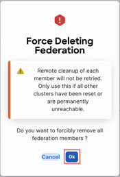
Once all the secondary clusters are disconnected, click Delete Federation to delete the federation.
-
In the confirmation window, click Ok.
This puts the local cluster into a fresh state, which allows it to be added to a new federation.
 Delete Federation
The action that’s taken when clicking Delete Federation varies depending on whether you’re logged in on a primary or a secondary cluster:
-
On the primary cluster: This will forcefully remove all members of the federation, including the primary. If any remote member is down or temporarily unreachable, federation info stored remotely on that member will not be cleaned up.
-
On a secondary cluster: This button will remove all local federation info from the cluster. This must be used only when the original primary member has been shut down permanently, or has been wiped of all federation info.
-
If this is used while the primary member is still active, the secondary member will rejoin the federation within a few minutes as part of periodic syncing done by the primary member.
-
If this is used while the primary member is not active, the secondary member will be deleted from the cluster federation and will be eligible to join or build a new federation.
-
Managing Secondary Nodes
You can add a number of secondary nodes to an existing 3-node cluster for horizontal scaling to enable application co-hosting.
For additional information about application co-hosting and cluster sizing, see the Platform Overview section of this document.
-
Secondary nodes are not supported for cloud form factors of Nexus Dashboard clusters deployed in AWS or Azure.
-
Secondary nodes are now qualified for NDFC IPFM fabric types. For more information about NDFC IPFM fabrics, see IPFM and Classic IPFM.
Adding Secondary Nodes
This section describes how to add a secondary node to your cluster to enable horizontal scaling
-
Ensure that the existing primary nodes and the cluster are healthy.
-
Prepare and deploy the new node.
-
Ensure that the node you are adding is powered on.
-
If you are adding a physical node, ensure that you have the new node’s CIMC IP address and login information.
You will need to use the CIMC information to add the new node using the Nexus Dashboard GUI.
-
If you are adding a virtual node, ensure that you have the node’s management IP address and login information.
To add a secondary node:
-
Log in to the Cisco Nexus Dashboard GUI.
-
From the main navigation menu, select System Resources > Nodes.
-
In the main pane, click Add Node.
The Add Node screen opens.
-
In the Add Node screen, provide the node information.
-
Provide the Name of the node.
-
From the Type dropdown, select
secondary. -
Provide the Credentials information for the node, then click Verify.
For physical nodes, this is the IP address, username, and password of the server’s CIMC. The CIMC will be used to configure the rest of the information on the node.
For virtual nodes, this is the IP address and
rescue-userpassword you defined for the node when deploying it. -
Provide the Management Network information.
For virtual nodes, the management network information will be pre-populated with the information pulled from the node based on the IP address and credentials you provided in the previous sub-step.
For physical nodes, you must provide the management network IP address, netmask, and gateway now.
-
Provide the Data Network information.
You must provide the data network IP address, netmask, and gateway. Optionally, you can also provide the VLAN ID for the network. For most deployments, you can leave the VLAN ID field blank.
-
(Optional) Provide IPv6 information for the management and data networks.
Starting with release 2.1.1, Nexus Dashboard supports dual stack IPv4/IPv6 for the management and data networks.
If you want to provide IPv6 information, you must do it when adding the node.
All nodes in the cluster must be configured with either only IPv4 or dual IPv4/IPv6 stack.
-
-
Click Save to add the node.
The configuration will be pushed to the node and the node will be added to the list in the GUI.
-
If you are running Nexus Dashboard Insights application, disable and re-enable the application.
After you add the new secondary node, you must disable and re-enable the application for its services to be properly distributed to the new node.
Deleting a Secondary node
-
Ensure that the primary nodes and the cluster are healthy.
To delete an existing secondary node:
-
Log in to the Cisco Nexus Dashboard GUI.
-
From the main navigation menu, select System Resources > Nodes.
-
Select the checkbox next to the secondary node you want to delete.
-
From the Actions menu, choose Delete to delete the node.
Managing Standby Nodes
You can add up to two standby nodes, which you can use to quickly restore the cluster functionality in case one or more primary nodes fail by replacing the failed primary node with the standby node.
Standby nodes are similar to secondary nodes in deployment, initial configuration, and upgrades. However, unlike secondary nodes, the cluster will not use the standby nodes for any workloads.
Standby nodes are not supported for single-node clusters or clusters deployed in AWS or Azure.
The following two cases are supported:
-
Single primary node failure
You can use the UI to convert the standby node into a new primary node.
-
Two primary nodes failure
You will need to perform manual failover of one of the nodes to restore cluster functionality. Then fail over the second node using standard procedure.
Adding Standby Nodes
This section describes how to add a standby node to your cluster for easy cluster recover in case of a primary node failure.
-
Ensure that the existing primary nodes and the cluster are healthy.
-
Prepare and deploy the new node.
You can failover only between nodes of identical types (physical or virtual), so you must deploy the same type of node as the nodes in your cluster which you may need to replace. In case of virtual nodes deployed in VMware ESX, which have two node profiles (
OVA-appandOVA-data), you can failover only between nodes of the same profile. -
Ensure that the node you are adding is powered on.
-
If you are adding a physical node, ensure that you have the new node’s CIMC IP address and login information.
You will need to use the CIMC information to add the new node using the Nexus Dashboard GUI.
-
If you are adding a virtual node, ensure that you have the node’s management IP address and login information.
To add a standby node:
-
Log in to the Cisco Nexus Dashboard GUI.
-
From the main navigation menu, select System Resources > Nodes.
-
In the main pane, click Add Node.
The Add Node screen opens.
-
In the Add Node screen, provide the node information.
-
Provide the Name of the node.
-
From the Type dropdown, select
Standby. -
Provide the Credentials information for the node, then click Verify.
For physical nodes, this is the IP address, username, and password of the server’s CIMC. The CIMC will be used to configure the rest of the information on the node.
For virtual nodes, this is the IP address and
rescue-userpassword you defined for the node when deploying it. -
Provide the Management Network information.
For virtual nodes, the management network information will be pre-populated with the information pulled from the node based on the IP address and credentials you provided in the previous sub-step.
For physical nodes, you must provide the management network IP address, netmask, and gateway now.
-
Provide the Data Network information.
You must provide the data network IP address, netmask, and gateway. Optionally, you can also provide the VLAN ID for the network. For most deployments, you can leave the VLAN ID field blank.
-
(Optional) Provide IPv6 information for the management and data networks.
Starting with release 2.1.1, Nexus Dashboard supports dual stack IPv4/IPv6 for the management and data networks.
If you want to provide IPv6 information, you must do it when adding the node.
All nodes in the cluster must be configured with either only IPv4 or dual IPv4/IPv6 stack.
-
-
Click Save to add the node.
The configuration will be pushed to the node and the node will be added to the list in the GUI.
Replacing Single Primary Node with Standby Node
This section describes failover using a pre-configured standby node. If your cluster does not have a standby node, follow the steps described in one of the sections in Troubleshooting instead.
-
Ensure that at least 2 primary nodes are healthy.
-
Ensure that you have at least one
standbynode available in the cluster.Setting up and configuring
standbynodes is described in Adding Standby Nodes. -
Ensure that the
primarynode you want to replace is powered off.
You cannot re-add the
primarynode you are replacing back to the cluster after the failover is complete. If theprimarynode you replace is still functional and you want to re-add it to the cluster after the failover, you must factory reset or re-image it as described in Troubleshooting and add it as astandbyorprimarynode only.
To failover a single primary node:
-
Log in to the Cisco Nexus Dashboard GUI.
-
From the main navigation menu, select System Resources > Nodes.
-
Click the Actions (…) menu next to the
Inactiveprimary node that you want to replace. -
Choose Failover.
Note that you must have a standby node already configured and added or the Failover menu option will not be available.
-
In the Fail Over window that opens, select a standby node from the dropdown.
-
Click Save to complete the failover.
The failed primary node will be removed from the list and replaced by the standby node you selected. The status will remain
Inactivewhile the services are being restored to the new primary node.It can take up to 10 minutes for all services to be restored, at which point the new primary node’s status will change to
Active.
Replacing Two Primary Nodes with Standby Node
Beginning with Nexus Dashboard release 3.2.1, the option to replace two primary nodes with a standby node is no longer supported. Instead, if one cluster becomes unavailable, you will recover that cluster from a backup that is available on another cluster. See the section "Recovering a Cluster" in Nexus Dashboard Troubleshooting for more information.
Deleting Standby Nodes
-
Ensure that the primary nodes and the cluster are healthy.
To delete an existing standby node:
-
Log in to the Cisco Nexus Dashboard GUI.
-
From the main navigation menu, select System Resources > Nodes.
-
Select the checkbox next to the standby node you want to delete.
-
From the Actions menu, choose Delete to delete the node.
Trademarks
THE SPECIFICATIONS AND INFORMATION REGARDING THE PRODUCTS IN THIS MANUAL ARE SUBJECT TO CHANGE WITHOUT NOTICE. ALL STATEMENTS, INFORMATION, AND RECOMMENDATIONS IN THIS MANUAL ARE BELIEVED TO BE ACCURATE BUT ARE PRESENTED WITHOUT WARRANTY OF ANY KIND, EXPRESS OR IMPLIED. USERS MUST TAKE FULL RESPONSIBILITY FOR THEIR APPLICATION OF ANY PRODUCTS.
THE SOFTWARE LICENSE AND LIMITED WARRANTY FOR THE ACCOMPANYING PRODUCT ARE SET FORTH IN THE INFORMATION PACKET THAT SHIPPED WITH THE PRODUCT AND ARE INCORPORATED HEREIN BY THIS REFERENCE. IF YOU ARE UNABLE TO LOCATE THE SOFTWARE LICENSE OR LIMITED WARRANTY, CONTACT YOUR CISCO REPRESENTATIVE FOR A COPY.
The Cisco implementation of TCP header compression is an adaptation of a program developed by the University of California, Berkeley (UCB) as part of UCB’s public domain version of the UNIX operating system. All rights reserved. Copyright © 1981, Regents of the University of California.
NOTWITHSTANDING ANY OTHER WARRANTY HEREIN, ALL DOCUMENT FILES AND SOFTWARE OF THESE SUPPLIERS ARE PROVIDED “AS IS" WITH ALL FAULTS. CISCO AND THE ABOVE-NAMED SUPPLIERS DISCLAIM ALL WARRANTIES, EXPRESSED OR IMPLIED, INCLUDING, WITHOUT LIMITATION, THOSE OF MERCHANTABILITY, FITNESS FOR A PARTICULAR PURPOSE AND NONINFRINGEMENT OR ARISING FROM A COURSE OF DEALING, USAGE, OR TRADE PRACTICE.
IN NO EVENT SHALL CISCO OR ITS SUPPLIERS BE LIABLE FOR ANY INDIRECT, SPECIAL, CONSEQUENTIAL, OR INCIDENTAL DAMAGES, INCLUDING, WITHOUT LIMITATION, LOST PROFITS OR LOSS OR DAMAGE TO DATA ARISING OUT OF THE USE OR INABILITY TO USE THIS MANUAL, EVEN IF CISCO OR ITS SUPPLIERS HAVE BEEN ADVISED OF THE POSSIBILITY OF SUCH DAMAGES.
Any Internet Protocol (IP) addresses and phone numbers used in this document are not intended to be actual addresses and phone numbers. Any examples, command display output, network topology diagrams, and other figures included in the document are shown for illustrative purposes only. Any use of actual IP addresses or phone numbers in illustrative content is unintentional and coincidental.
Cisco and the Cisco logo are trademarks or registered trademarks of Cisco and/or its affiliates in the U.S. and other countries. To view a list of Cisco trademarks, go to this URL: http://www.cisco.com/go/trademarks. Third-party trademarks mentioned are the property of their respective owners. The use of the word partner does not imply a partnership relationship between Cisco and any other company. (1110R)
© 2017-2024 Cisco Systems, Inc. All rights reserved.
First Published: 2024-03-01
Last Modified: 2024-03-01
Americas Headquarters
Cisco Systems, Inc.
170 West Tasman Drive
San Jose, CA 95134-1706
USA
http://www.cisco.com
Tel: 408 526-4000
800 553-NETS (6387)
Fax: 408 527-0883