About this Guide
Audience
The audience for this document includes network design engineers, network operations personnel, and security operations personnel who don't have physical appliances for Cisco Catalyst Center, Cisco Identity Services Engine (ISE), and others. These network specialists are already DNA-entitled and wish to manage their networks using a Catalyst Center Virtual Appliance (VA) and Cisco ISE running on Cloud for Authentication and Authorization.
Purpose
This guide helps you design, deploy, and operate the following Cisco products as Infrastructure as a Service (IaaS) in a single Amazon Web Services (AWS) Virtual Private Cloud (VPC):
-
Catalyst Center VA
-
Cisco ISE
-
Cisco Catalyst 9800-CL Wireless Controller
The guide discusses the interworkings of these Cisco products when deployed together in the following deployment models:
-
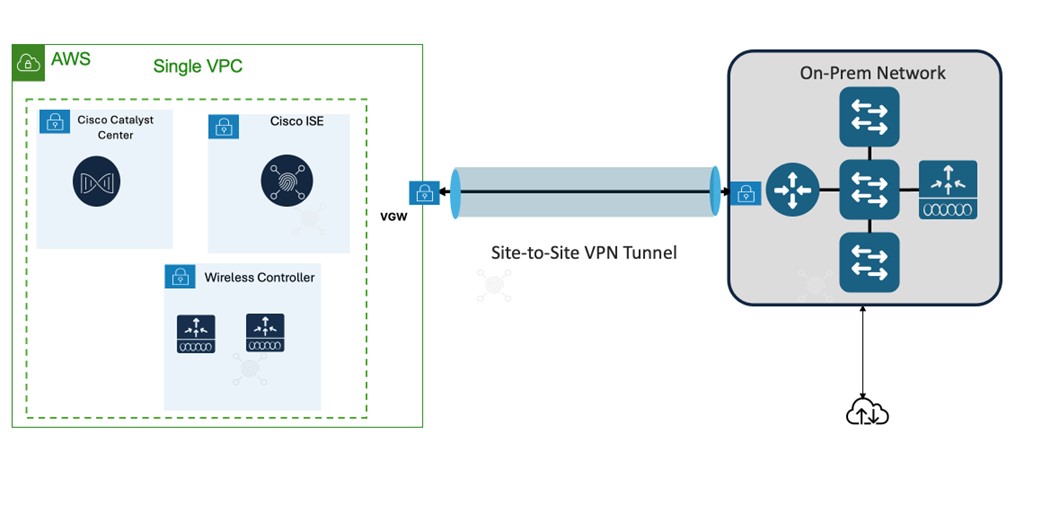
A single AWS VPC connecting to on-premises network devices using an AWS Virtual Private Gateway (VGW)
-
Different AWS VPCs connecting on-premises network devices using an AWS Transit Gateway (TGW)
The guide also provides the following information:
-
Requirements to deploy these enterprise products successfully in AWS.
-
Procedures that detail how to deploy and configure these products using a Quick Start workflow.
-
Post-deployment tasks that should be carried out before these products are ready to use.
Organization
This document organization follows the implementation flow:
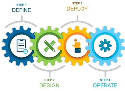
As such, it contains these four main sections:
-
Define the Solution: Presents a high-level overview of the Catalyst Center VA, Cisco ISE, and Catalyst 9800-CL Wireless Controller as IaaS.
-
Design the Solution and Review Prerequisites: Discusses the prerequisites for this deployment. Topics include supported scale, latency recommendations, and bandwidth requirements, known limitations of the individual products, guidelines for integrating Cisco ISE with Catalyst Center on AWS, High Availability support in AWS, and security considerations.
-
Deploy the Solution: Provides deployment procedures and post-deployment best practices for:
-
Catalyst Center VA using Cisco Global Launchpad (an automated Cisco utility used to deploy AWS infrastructure and Catalyst Center on AWS), AWS CloudFormation, or AWS Marketplace
-
Cisco ISE
-
Catalyst 9800-CL Wireless Controller
-
-
Operate the Solution: Shows some of the capabilities of Amazon CloudWatch that can be used to monitor and troubleshoot the Catalyst Center VA, Cisco ISE, and Cisco Catalyst 9800-CL Wireless Controller deployment.
Define the Solution
Catalyst Center on AWS Overview
 Note |
Cisco DNA Center has been rebranded as Catalyst Center, and Cisco DNA Center VA Launchpad has been rebranded as Cisco Global Launchpad. During the rebranding process, you will see the former and rebranded names used in different collaterals. However, Cisco DNA Center and Catalyst Center refer to the same product, and Cisco DNA Center VA Launchpad and Cisco Global Launchpad refer to the same product. |
Catalyst Center offers centralized, intuitive management that makes it fast and easy to design, provision, and apply policies across your network environment. The Catalyst Center user interface provides end-to-end network visibility and uses network insights to optimize network performance and deliver the best user and application experience.
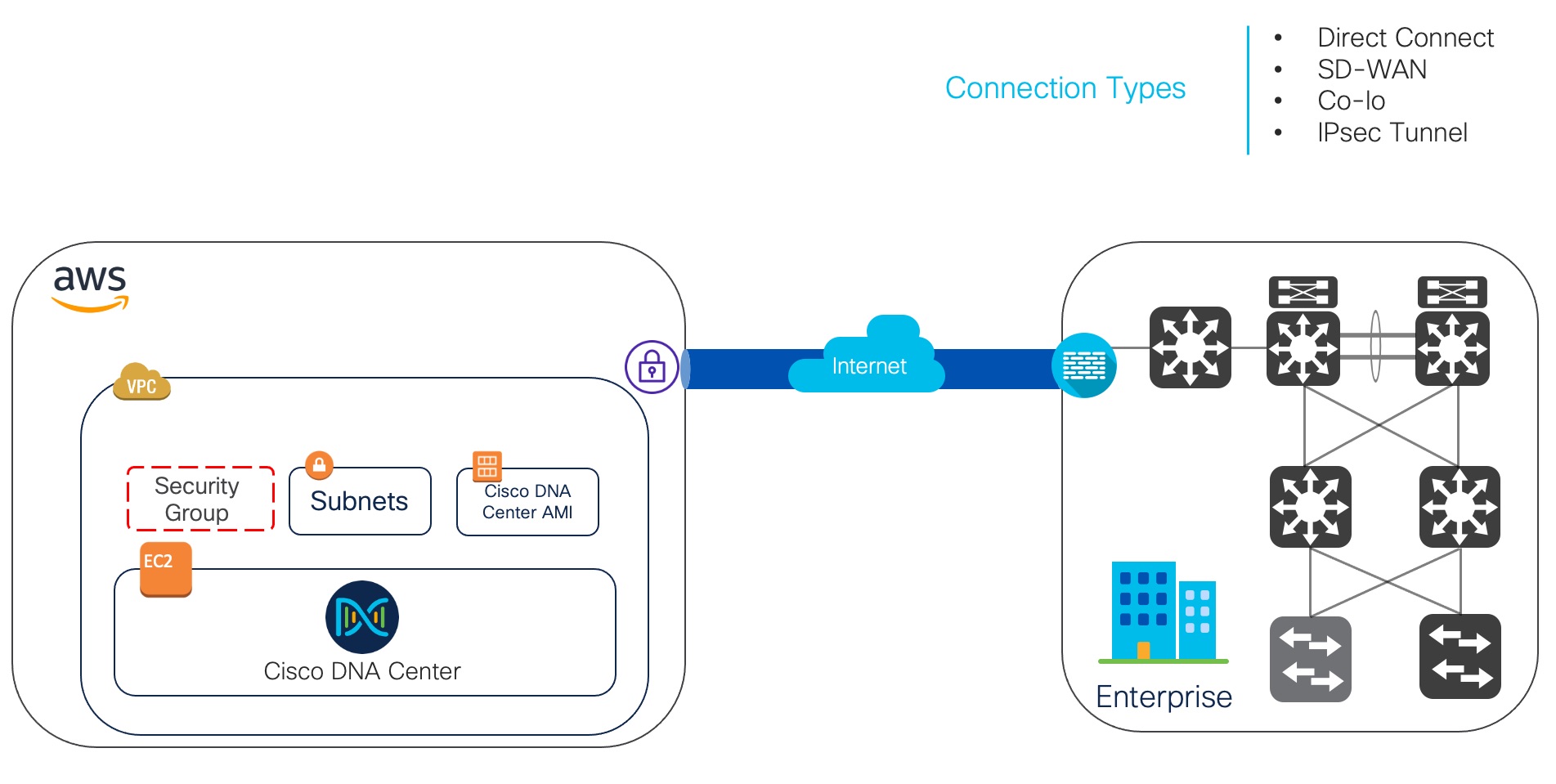
Catalyst Center on Amazon Web Services (AWS) provides the full functionality that a Catalyst Center appliance deployment offers. Catalyst Center on AWS runs in your AWS cloud environment and manages your network from the cloud.
Cisco ISE on AWS
Extend the Cisco ISE policies in your home network to new remote deployments securely through Amazon Web Services (AWS).
You can configure and launch Cisco ISE in AWS through AWS CloudFormation Templates (CFTs) or Amazon Machine Images (AMIs). We recommend that you use CFTs through one of the ways in the following list. To launch Cisco ISE on AWS, perform one of the following procedures:
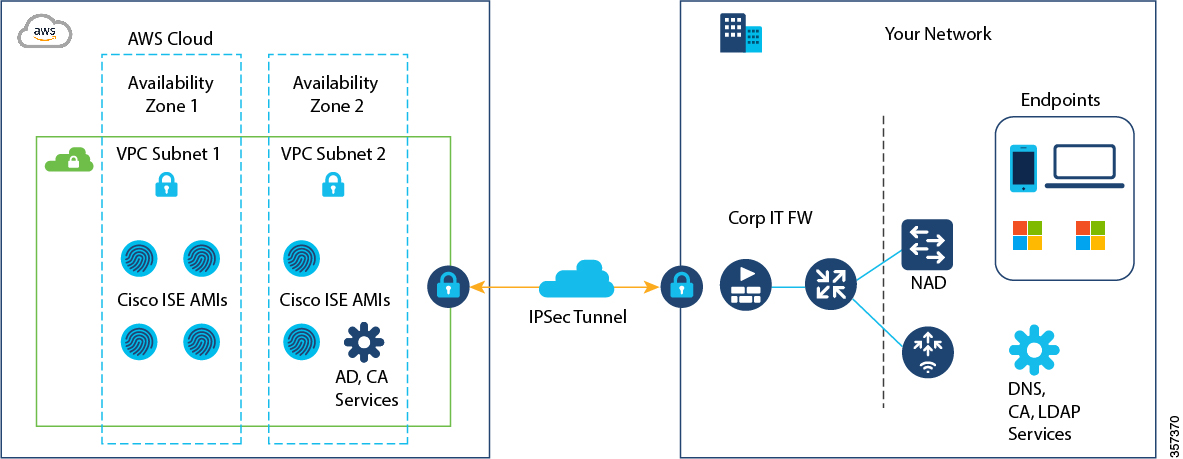
CFTs are AWS solutions that allow you to easily create and manage cloud deployments. Extend your network into the cloud by creating a virtual private cloud in AWS and configure a virtual private gateway to enable communication with your organization's network over an IPsec tunnel.
The following illustration is only an example. You can place common services such as Certificate Authority (CA), Active Directory (AD), Domain Name System (DNS) servers, and Lightweight Directory Access Protocol (LDAP) on premises or in AWS, based on the requirements of your organization.
For information about using CFTs in AWS, see the AWS CloudFormation User Guide.
The following table contains details of the Cisco ISE instances that are currently available. You must purchase a Cisco ISE VM license to use any of the following instances. See Amazon EC2 On-Demand Pricing for information on EC2 instance pricing for your specific requirements.
|
Cisco ISE Instance Type |
CPU Cores |
RAM (in GB) |
|---|---|---|
|
t3.xlarge This instance supports the Cisco ISE evaluation use case and is supported in Cisco ISE Release 3.1 Patch 1 and later. 100 concurrent active endpoints are supported. |
4 |
16 |
|
m5.2xlarge |
8 |
32 |
|
c5.4xlarge |
16 |
32 |
|
m5.4xlarge |
16 |
64 |
|
c5.9xlarge |
36 |
72 |
|
m5.8xlarge |
32 |
128 |
|
m5.16xlarge |
64 |
256 |
Compute-optimized instances such as c5.4xlarge and c5.9xlarge are intended for compute-intensive tasks or applications and are best suited for Policy Service Node (PSN) use.
General purpose instances such as m5.4xlarge are intended for data processing tasks and database operations and are best suited for use as Policy Administration Node (PAN) or Monitoring and Troubleshooting (MnT) nodes, or both.
If you use a general purpose instance as a PSN, the performance numbers are lower than the performance of a compute-optimized instance as a PSN.
For information on the scale and performance data for AWS instance types, see the Performance and Scalability Guide for Cisco Identity Services Engine.
You can leverage the AWS S3 storage service to easily store backup and restore files, monitoring and troubleshooting reports, and more. See Configure A Cisco ISE Release 3.1 Repository With AWS S3.
In addition to the procedures explained above, you can also use the following Cisco developed solutions to install and automatically create multinode Cisco ISE deployments on AWS:
-
Cisco ISE AWS Partner Solution for small deployments.
-
Cisco Developed Terraform Script for deployments of any size.
Cisco Catalyst 9800-CL Wireless Controller Hosted on AWS
This section describes the wireless controller hosted on AWS deployment, which uses a cloud-based Cisco Catalyst 9800-CL Wireless Controller hosted on AWS. For more information, see Deployment guide for Cisco Catalyst 9800 Wireless Controller for Cloud (C9800-CL) on Amazon Web Services (AWS).
Launching a Catalyst 9800-CL Wireless Controller Amazon Machine Image (AMI) occurs directly from AWS Marketplace. The Catalyst 9800-CL Wireless Controller is deployed on an Amazon EC2 in an AWS Virtual Private Cloud (VPC).
Cisco supports the following instance type for the first release of the Cisco Catalyst 9800-CL Wireless Controller in the cloud:
C5.xlarge: 4 vCPUs, 8 GB RAM, 8GB Disk with 1 vNIC.
The allocated resources will allow the instance to scale to 1000 APs and 10,000 clients.
Design the Solution and Review Prerequisites
Topology
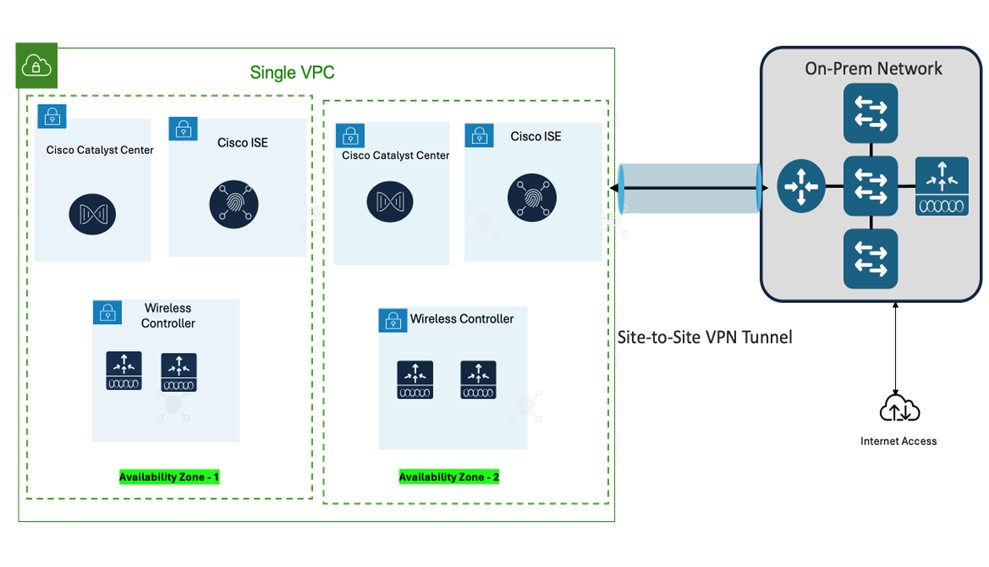
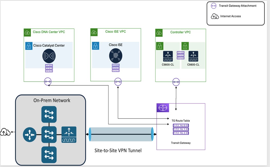
Catalyst Center VAs, Cisco ISE, and Catalyst 9800-CL Wireless Controllers that are located in an AWS Public Cloud can be deployed in different topologies:
-
Single VPC deployment for Catalyst Center VA, Cisco ISE, and Catalyst 9800-CL Wireless Controller instances:
-
Single VPC, same Availability Zone - Same Subnet
-
Single VPC, different Availability Zone – different subnets per AZ
-
-
Individual VPC deployment for Catalyst Center VA, Cisco ISE, Catalyst 9800-CL Wireless Controller instances:
-
Same Availability Zone for all individual VPCs
-
Different Availability Zone for individual VPCs
-
Prerequisites for Catalyst Center VA
Prerequisites for Automated Deployment
Before you can begin to deploy Catalyst Center on AWS using Cisco Global Launchpad, make sure that the following requirements are met:
-
Install Docker Community Edition (CE) on your platform.
Cisco Global Launchpad supports Docker CE on Mac, Windows, and Linux platforms. See the documentation on the Docker website for the specific procedure for your platform.
-
Regardless of how you access Cisco Global Launchpad, your Catalyst Center VA must meet the following minimum resource requirements:
-
Catalyst Center Instance:
-
r5a.8xlarge

Important
Catalyst Center supports only the r5a.8xlarge instance size. Any changes to this configuration aren't supported. Additionally, the r5a.8xlarge instance size isn't supported in specific availability zones. To view the list of unsupported availability zones, see the Release Notes for Cisco Global Launchpad.
-
32 vCPUs
-
256-GB RAM
-
4-TB storage (EBS-gp3)
-
2500 disk input/output operations per second (IOPS)
-
180-MBps disk bandwidth
-
-
Backup Instance: T3.micro, 2 vCPUs, 500-GB storage, and 1-GB RAM
-
-
You have valid credentials to access your AWS account.
-
Your AWS account is a subaccount (a child account) to maintain resource independence and isolation. With a subaccount, this ensures that the Catalyst Center deployment doesn't impact your existing resources.
-
Important: Your AWS account is subscribed to Cisco Catalyst Center Virtual Appliance - Bring Your Own License (BYOL) in AWS Marketplace.
-
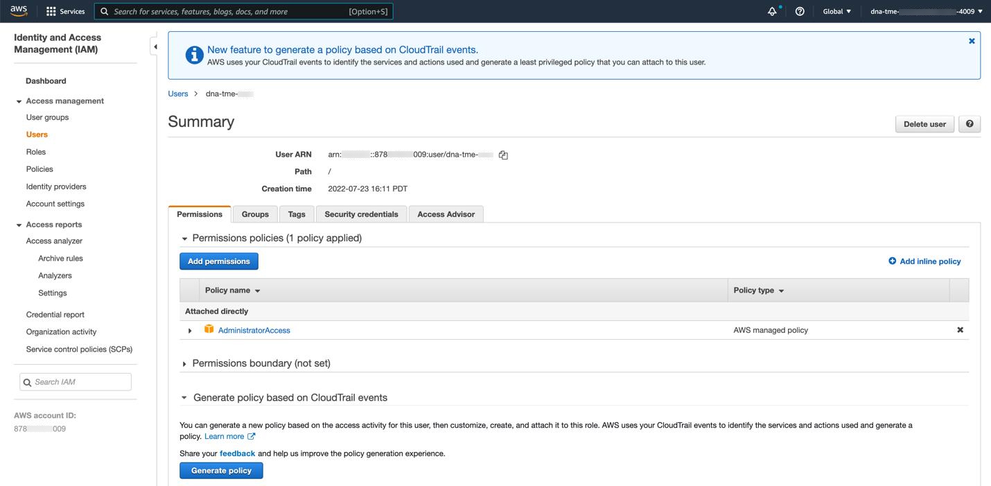
If you're an admin user, you must have administrator access permission for your AWS account. (In AWS, the policy name is displayed as AdministratorAccess.)
The administrator access policy must be attached to your AWS account directly and not to a group. The application doesn't enumerate through a group policy. So, if you are added to a group with the administrator access permission, you will not be able to create the required infrastructure.
-
If you're a subuser, your administrator must add you to the CiscoDNACenter user group.
When an admin user logs in to Cisco Global Launchpad for the first time, the CiscoDNACenter user group is created on their AWS account with all the required policies attached. The admin user can add subusers to this group to allow them to log in to Cisco Global Launchpad.
The following policies are attached to the CiscoDNACenter user group:
-
AmazonDynamoDBFullAccess
-
IAMReadOnlyAccess
-
AmazonEC2FullAccess
-
AWSCloudFormationFullAccess
-
AWSLambda_FullAccess
-
CloudWatchFullAccess
-
ServiceQuotasFullAccess
-
AmazonEventBridgeFullAccess
-
service-role/AWS_ConfigRole
-
AmazonS3FullAccess
-
ClientVPNServiceRolePolicy (Version: 2012-10-17)
This policy allows the following rules:
-
ec2:CreateNetworkInterface
-
ec2:CreateNetworkInterfacePermission
-
ec2:DescribeSecurityGroups
-
ec2:DescribeVpcs
-
ec2:DescribeSubnets
-
ec2:DescribeInternetGateways
-
ec2:ModifyNetworkInterfaceAttribute
-
ec2:DeleteNetworkInterface
-
ec2:DescribeAccountAttributes
-
ds:AuthorizeApplication
-
ds:DescribeDirectories
-
ds:GetDirectoryLimits
-
ds:UnauthorizeApplication
-
logs:DescribeLogStreams
-
logs:CreateLogStream
-
logs:PutLogEvents
-
logs:DescribeLogGroups
-
acm:GetCertificate
-
acm:DescribeCertificate
-
iam:GetSAMLProvider
-
lambda:GetFunctionConfiguration
-
-
ConfigPermission (Version: 2012-10-17, Sid: VisualEditor0)
This policy allows the following rules:
-
config:Get
-
config:*
-
config:*ConfigurationRecorder
-
config:Describe*
-
config:Deliver*
-
config:List*
-
config:Select*
-
tag:GetResources
-
tag:GetTagKeys
-
cloudtrail:DescribeTrails
-
cloudtrail:GetTrailStatus
-
cloudtrail:LookupEvents
-
config:PutConfigRule
-
config:DeleteConfigRule
-
config:DeleteEvaluationResults
-
-
PassRole (Version: 2012-10-17, Sid: VisualEditor0)
This policy allows the following rules:
-
iam:GetRole
-
iam:PassRole
-
-
Prerequisites for Manual Deployment Using AWS CloudFormation
Before you can begin to deploy Catalyst Center on AWS, make sure that the following network, AWS, and Catalyst Center requirements have been met:
Network Environment
You must have the following information about your network environment on hand:
-
Enterprise DNS server IP address
-
(Optional) HTTPS Network Proxy details
AWS Environment
You must meet the following AWS environment requirements:
-
You have valid credentials to access your AWS account.

Note
We recommend that your AWS account be a subaccount (a child account) to maintain resource independence and isolation. A subaccount ensures that the Catalyst Center deployment does not impact your existing resources.
-
Important: Your AWS account is subscribed to Catalyst Center Virtual Appliance - Bring Your Own License (BYOL) in AWS Marketplace.
-
You must have administrator access permission for your AWS account. (In AWS, the policy name is displayed as AdministratorAccess.)

-
The following resources and services must be set up in AWS:
-
VPC: The recommended CIDR range is /25. In IPv4 CIDR notation, the last octet (the fourth octet) of the IP address can only have the values 0 or 128. For example: x.x.x.0 or x.x.x.128.
-
Subnets: The recommended subnet range is /28 and should not overlap with your corporate subnet.
-
Route Tables: Make sure that your VPC subnet is allowed to communicate with your Enterprise network via your VPN GW or TGW.
-
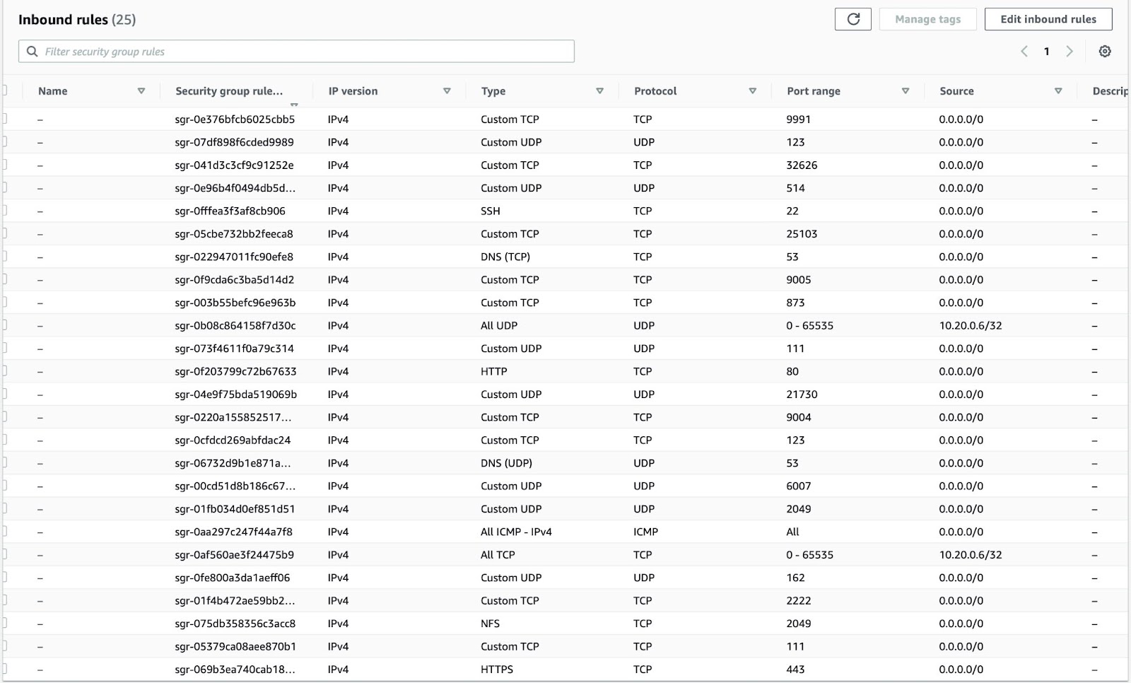
Security Groups: For communication between your Catalyst Center VA on AWS and the devices in your Enterprise network, the AWS security group that you attach to your Catalyst Center VA on AWS must allow the following ports:
-
TCP 22, 80, 443, 9991, 25103, 32626
-
UDP 123, 162, 514, 6007, 21730
The following table lists information about the ports that Catalyst Center uses, the services communicating over these ports, the appliance's purpose in using them, and the recommended action.
Port Service Name Purpose Recommended Action —
ICMP
Devices use ICMP messages to communicate network connectivity issues.
Enable ICMP.
TCP 22, 80, 443
HTTPS, SFTP, HTTP
Software image download from Catalyst Center through HTTPS:443, SFTP:22, HTTP:80.
Certificate download from Catalyst Center through HTTPS:443, HTTP:80 (Cisco 9800 Wireless Controller, PnP), Sensor/Telemetry.
Note
Block port 80 if you don't use Plug and Play (PnP), Software Image Management (SWIM), Embedded Event Management (EEM), device enrollment, or Cisco 9800 Wireless Controller.
Ensure that firewall rules limit the source IP of the hosts or network devices allowed to access Catalyst Center on these ports.
Note
We do not recommend the use of HTTP 80. Use HTTPS 443 wherever possible.
UDP 123
NTP
Devices use NTP for time synchronization.
Port must be open to allow devices to synchronize the time.
UDP 162
SNMP
Catalyst Center receives SNMP network telemetry from devices.
Port must be open for data analytics based on SNMP.
UDP 514
Syslog
Catalyst Center receives syslog messages from devices.
Port must be open for data analytics based on syslog.
UDP 6007
NetFlow
Catalyst Center receives NetFlow network telemetry from devices.
Port must be open for data analytics based on NetFlow.
TCP 9991
Wide Area Bonjour Service
Catalyst Center receives multicast Domain Name System (mDNS) traffic from the Service Discovery Gateway (SDG) agents using the Bonjour Control Protocol.
Port must be open on Catalyst Center if the Bonjour application is installed.
UDP 21730
Application Visibility Service
Application Visibility Service CBAR device communication.
Port must be open when CBAR is enabled on a network device.
TCP 25103
Cisco 9800 Wireless Controller and Cisco Catalyst 9000 switches with streaming telemetry enabled
Used for telemetry.
Port must be open for telemetry connections between Catalyst Center and Catalyst 9000 devices.
TCP 32626
Intelligent Capture (gRPC) collector
Used for receiving traffic statistics and packet - capture data used by the Assurance Intelligent Capture (gRPC) feature.
Port must be open if you are using the Assurance Intelligent Capture (gRPC) feature.
-
-
VPN Gateway (VPN GW) or Transit Gateway (TGW): You must have an existing connection to your Enterprise network, which is your Customer Gateway (CGW).
For your existing connection from the CGW to AWS, make sure that the correct ports are open for traffic flow to and from the Catalyst Center VA, whether you open them using the firewall settings or a proxy gateway. For more information about the well-known network service ports that the appliance uses, see "Required Network Ports" in the "Plan the Deployment" chapter of the Cisco Catalyst Center Appliance Installation Guide.
-
Site-to-Site VPN Connection: You can use TGW Attachments and TGW Route Tables.
-
-
Your AWS environment must be configured with supported regions described in AWS supported regions.
-
If you want to enable multiple IAM users with the ability to configure Catalyst Center using the same environment setup, you need to create a group with the following policies and then add the required users to that group:
-
IAMReadOnlyAccess
-
AmazonEC2FullAccess
-
AWSCloudFormationFullAccess
-
-
You have the following AWS information on hand:
-
Subnet ID
-
Security Group ID
-
Keypair ID
-
Environment name
-
CIDR reservation
-
Catalyst Center Environment
You must meet the following requirements for your Catalyst Center environment:
-
You have access to the Catalyst Center GUI.
-
You have the following Catalyst Center information on hand:
-
Default gateway setting
-
CLI password
-
FQDN for the Catalyst Center VA IP address
-
Prerequisites for Manual Deployment Using AWS Marketplace
Before you can begin to deploy Catalyst Center on AWS, make sure that the following network, AWS, and Catalyst Center requirements have been met:
Network Environment
You must have the following information about your network environment on hand:
-
Enterprise DNS server IP address
-
(Optional) HTTPS Network Proxy details
AWS Environment
You must meet the following AWS environment requirements:
-
You have valid credentials to access your AWS account.

Note
We recommend that your AWS account be a subaccount (a child account) to maintain resource independence and isolation. A subaccount ensures that the Catalyst Center deployment does not impact your existing resources.
-
Important: Your AWS account is subscribed to Catalyst Center Virtual Appliance - Bring Your Own License (BYOL) in AWS Marketplace.
-
You must have administrator access permission for your AWS account. (In AWS, the policy name is displayed as AdministratorAccess.)

-
The following resources and services must be set up in AWS:
-
VPC: The recommended CIDR range is /25. In IPv4 CIDR notation, the last octet (the fourth octet) of the IP address can only have the values 0 or 128. For example: x.x.x.0 or x.x.x.128.
-
Subnets: The recommended subnet range is /28 and should not overlap with your corporate subnet.
-
Route Tables: Make sure that your VPC subnet is allowed to communicate with your Enterprise network via your VPN GW or TGW.
-
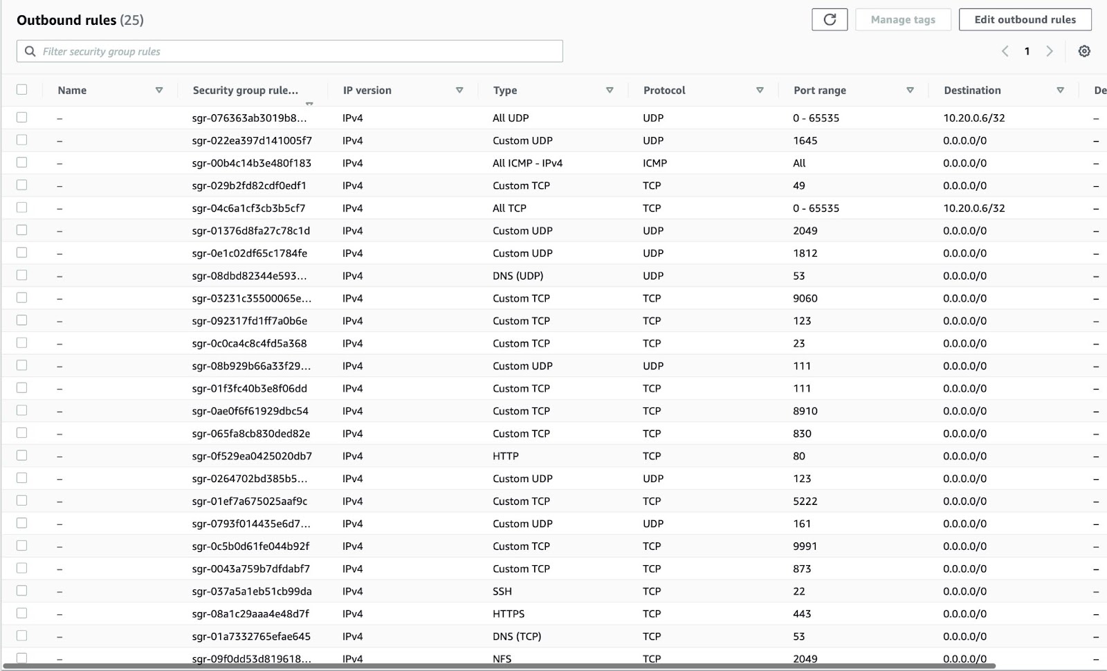
Security Groups: For communication between the Catalyst Center on AWS and the devices in your Enterprise network, the AWS security group that you attach to the Catalyst Center on AWS must allow the following ports:
-
TCP 22, 80, 443, 9991, 25103, 32626
-
UDP 123, 162, 514, 6007, 21730
You must also configure the inbound and outbound ports. To configure inbound ports, refer to the following figure:
To configure outbound ports, refer to the following figure:
The following table lists information about the ports that Catalyst Center uses, the services communicating over these ports, the appliance's purpose in using them, and the recommended action.
Port Service Name Purpose Recommended Action —
ICMP
Devices use ICMP messages to communicate network connectivity issues.
Enable ICMP.
TCP 22, 80, 443
HTTPS, SFTP, HTTP
Software image download from Catalyst Center through HTTPS:443, SFTP:22, HTTP:80.
Certificate download from Catalyst Center through HTTPS:443, HTTP:80 (Cisco 9800 Wireless Controller, PnP), Sensor/Telemetry.
Note
Block port 80 if you don't use Plug and Play (PnP), Software Image Management (SWIM), Embedded Event Management (EEM), device enrollment, or Cisco 9800 Wireless Controller.
Ensure that firewall rules limit the source IP of the hosts or network devices allowed to access Catalyst Center on these ports.
Note
We do not recommend the use of HTTP 80. Use HTTPS 443 wherever possible.
UDP 123
NTP
Devices use NTP for time synchronization.
Port must be open to allow devices to synchronize the time.
UDP 162
SNMP
Catalyst Center receives SNMP network telemetry from devices.
Port must be open for data analytics based on SNMP.
UDP 514
Syslog
Catalyst Center receives syslog messages from devices.
Port must be open for data analytics based on syslog.
UDP 6007
NetFlow
Catalyst Center receives NetFlow network telemetry from devices.
Port must be open for data analytics based on NetFlow.
TCP 9991
Wide Area Bonjour Service
Catalyst Center receives multicast Domain Name System (mDNS) traffic from the Service Discovery Gateway (SDG) agents using the Bonjour Control Protocol.
Port must be open on Catalyst Center if the Bonjour application is installed.
UDP 21730
Application Visibility Service
Application Visibility Service CBAR device communication.
Port must be open when CBAR is enabled on a network device.
TCP 25103
Cisco 9800 Wireless Controller and Cisco Catalyst 9000 switches with streaming telemetry enabled
Used for telemetry.
Port must be open for telemetry connections between Catalyst Center and Catalyst 9000 devices.
TCP 32626
Intelligent Capture (gRPC) collector
Used for receiving traffic statistics and packet - capture data used by the Assurance Intelligent Capture (gRPC) feature.
Port must be open if you are using the Assurance Intelligent Capture (gRPC) feature.
-
-
VPN Gateway (VPN GW) or Transit Gateway (TGW): You must have an existing connection to your Enterprise network, which is your Customer Gateway (CGW).
For your existing connection from the CGW to AWS, make sure that the correct ports are open for traffic flow to and from your Catalyst Center VA, whether you open them using the firewall settings or a proxy gateway. For more information about the well-known network service ports that the appliance uses, see "Required Network Ports" in the "Plan the Deployment" chapter of the Cisco Catalyst Center Appliance Installation Guide.
-
Site-to-Site VPN Connection: You can use TGW Attachments and TGW Route Tables.
-
-
Your AWS environment must be configured with one of the following regions:
-
ap-northeast-1 (Tokyo)
-
ap-northeast-2 (Seoul)
-
ap-south-1 (Mumbai)
-
ap-southeast-1 (Singapore)
-
ap-southeast-2 (Sydney)
-
ca-central-1 (Canada)
-
eu-central-1 (Frankfurt)
-
eu-south-1 (Milan)
-
eu-west-1 (Ireland)
-
eu-west-2 (London)
-
eu-west-3 (Paris)
-
us-east-1 (Virginia)
-
us-east-2 (Ohio)
-
us-west-1 (N. California)
-
us-west-2 (Oregon)
-
-
If you want to enable multiple IAM users with the ability to configure Catalyst Center using the same environment setup, you need to create a group with the following policies and then add the required users to that group:
-
IAMReadOnlyAccess
-
AmazonEC2FullAccess
-
AWSCloudFormationFullAccess
-
-
You have the following AWS information on hand:
-
Subnet ID
-
Security Group ID
-
Keypair ID
-
Environment name
-
CIDR reservation
-
Catalyst Center Environment
You must meet the following requirements for your Catalyst Center environment:
-
You have access to the Catalyst Center GUI.
-
You have the following Catalyst Center information on hand:
-
NTP setting
-
Default gateway setting
-
CLI password
-
UI username and password
-
Static IP
-
FQDN for the Catalyst Center IP address
-
Verify the Catalyst Center VA TAR File
Before deploying the Catalyst Center VA, we strongly recommend that you verify that the TAR file you downloaded is a genuine Cisco TAR file.
Before you begin
Ensure that you've downloaded Catalyst Center VA TAR file from the Cisco Software Download site.
Procedure
|
Step 1 |
Download the Cisco public key (cisco_image_verification_key.pub) for signature verification from the location specified by Cisco. |
||
|
Step 2 |
Download the secure hash algorithm (SHA512) checksum file for the TAR file from the location specified by Cisco. |
||
|
Step 3 |
Obtain the TAR file's signature file (.sig) from Cisco support through email or by download from the secure Cisco website (if available). |
||
|
Step 4 |
(Optional) Perform an SHA verification to determine whether the TAR file is corrupted due to a partial download. Depending on your operating system, enter one of the following commands:
Microsoft Windows does not include a built-in checksum utility, but you can use the certutil tool: For example: On Windows, you can also use Windows PowerShell to generate the digest. For example: Compare the command output to the SHA512 checksum file that you downloaded. If the command output does not match, download the TAR file again and run the appropriate command a second time. If the output still does not match, contact Cisco support. |
||
|
Step 5 |
Verify that the TAR file is genuine and from Cisco by verifying its signature: openssl dgst -sha512 -verify cisco_image_verification_key.pub -signature <signature-filename> <tar-file-filename>
If the TAR file is genuine, running this command displays a |
Prerequisites for Cisco ISE on AWS
-
The following table contains details of the Cisco ISE instances that are currently available. You must purchase a Cisco ISE VM license to use any of the following instances. See Amazon EC2 On-Demand Pricing for information on EC2 instance pricing for your specific requirements.
Table 2. Cisco ISE Instances Cisco ISE Instance Type
CPU Cores
RAM (in GB)
t3.xlarge
This instance supports the Cisco ISE evaluation use case and is supported in Cisco ISE Release 3.1 Patch 1 and later releases. 100 concurrent active endpoints are supported.
4
16
m5.2xlarge
8
32
c5.4xlarge
16
32
m5.4xlarge
16
64
c5.9xlarge
36
72
m5.8xlarge
32
128
m5.16xlarge
64
256
-
Compute-optimized instances such as c5.4xlarge and c5.9xlarge are intended for compute-intensive tasks or applications and are best suited for Policy Service Node (PSN) use.
-
General purpose instances such as m5.4xlarge are intended for data processing tasks and database operations and are best suited for use as Policy Administration Node (PAN) or Monitoring and Troubleshooting (MnT) nodes, or both.
-
If you use a general purpose instance as a PSN, the performance numbers are lower than the performance of a compute-optimized instance as a PSN.
-
For information on the scale and performance data for AWS instance types, see the Performance and Scalability Guide for Cisco Identity Services Engine.
-
You can leverage the Amazon S3 storage service to easily store backup and restore files, monitoring and troubleshooting reports, and more. See Configure A Cisco ISE Release 3.1 Repository With AWS S3.
-
Users need to be familiar with AWS solutions such as Amazon EC2 instances and Amazon Elastic Block Storage (EBS) volumes, and concepts such as Regions, Availability Zones, Security Groups, Virtual Private Cloud (VPC), and so on. See the AWS documentation for information on these solutions.
-
Must also be familiar with managing AWS service quotas.
-
Configure VPC in AWS. See VPC with public and private subnets and AWS Site-to-Site VPN access.
-
To create encrypted EBS volumes, your AWS Identity and Access Management (IAM) policy must allow access to Key Management Service (KMS) resources. See Policies and permissions in IAM.
-
Create security groups, subnets, and key pairs in AWS before you configure a Cisco ISE instance.
-
When you create a security group for Cisco ISE, you must create rules for all the ports and protocols for the Cisco ISE services you want to use. See Chapter "Cisco ISE Ports Reference" in the Cisco ISE Installation Guide for your release.
-
The IP address that you enter in the Management Network field in the Cisco ISE CloudFormation template must not be an IP address that exists as a network interface object in AWS.
-
You can configure a static IP as a private IP in your deployment. However, the static IP must be configured with a DNS-resolvable hostname.
Prerequisites for Catalyst 9800-CL Wireless Controller on AWS
-
Create a managed VPN connection from the corporate network to the VPC.
-
Create a VPC with the desired subnet for the wireless management interface on the Catalyst 9800-CL Wireless Controller.
-
You do not have to configure the AWS CloudFormation template because the template is automatically integrated in the launching procedure. If desired, you can download and view the AWS CloudFormation template file from AWS Marketplace for the product.
-
Obtain the Amazon Machine Image ID (AMI-ID) for the desired Catalyst 9800-CL Wireless Controller software release. The AMI is available in AWS Marketplace.
-
As an option, you can restrict AP access to your instance for security reasons. For example, you can allow CAPWAP from a single, specific IP range so that only those APs are able to register to the controller. Here is the list of protocols you might need to enable inbound and outbound:
Port
Protocol
UDP 5246/5247/5248
CAPWAP
TCP 22
SSH, SCP
TCP 21
FTP
ICMP
Ping
UDP 161, 162
SNMP/SNMP traps
TCP 443/80
HTTPS/HTTP
TCP/UDP 49
TACACS+
UDP 53
DNS Server
UDP 1812/1645/1813/1646
Radius
UDP 123
NTP Server
UDP 514
Syslog
Known Limitations
Known Limitations of Using Catalyst Center on AWS
-
Catalyst Center on AWS supports only the r5a.8xlarge instance size. Any changes to this configuration aren't supported.
-
Catalyst Center on AWS doesn't support the Federal Information Processing Standards (FIPS).
-
Catalyst Center on AWS doesn't support IPv6.
-
Catalyst Center on AWS doesn't support disaster recovery. Therefore, we recommend that you don't install the optional Disaster Recovery (DR) package.
Known Limitations of Using Cisco ISE on AWS
The following are the known limitations with using Cisco ISE in AWS:
-
You cannot take an Amazon EBS snapshot of a Cisco ISE instance and then create another EBS volume with the snapshot.
-
The Amazon VPC supports only Layer 3 features. Cisco ISE nodes on AWS instances do not support Cisco ISE functions that depend on Layer 1 and Layer 2 capabilities. For example, working with DHCP SPAN profiler probes and CDP protocols that use the Cisco ISE CLI is currently not supported.
-
NIC bonding is not supported.
-
Dual NIC is supported with only two NICs—Gigabit Ethernet 0 and Gigabit Ethernet 1. To configure a secondary NIC in your Cisco ISE instance, you must first create a network interface object in AWS, power off your Cisco ISE instance, and then attach this network interface object to Cisco ISE. After you install and launch Cisco ISE on AWS, use the Cisco ISE CLI to manually configure the IP address of the network interface object as the secondary NIC.
-
Cisco ISE upgrade workflow is not available in Cisco ISE on AWS. Only fresh installs are supported. However, you can carry out backup and restore of configuration data. When you restore the data in a Cisco ISE AWS instance, the data is upgraded to the Cisco ISE Release 3.1 version. For information on upgrading hybrid Cisco ISE deployments, see Upgrade Guidelines for Hybrid Deployments.
-
SSH access to Cisco ISE CLI using password-based authentication is not supported in AWS. You can only access the Cisco ISE CLI through a key pair, and this key pair must be stored securely.
If you use a private key (or PEM) file and you lose the file, you will not be able to access the Cisco ISE CLI.
Any integration that uses a password-based authentication method to access Cisco ISE CLI is not supported, for example, Cisco DNA Center Release 2.1.2 and earlier.
-
You might receive an
Insufficient Virtual Machine Resourcesalarm when Cisco ISE is in idle state. You can ignore this alarm because the CPU frequency is maintained lower than the required baseline frequency (2 GHz) for effective power conservation. -
In the software version Cisco ISE 3.1, when you run the show inventory command through a Cisco ISE instance that is launched through AWS, the output for the command does not display the instance type of the Cisco ISE on AWS in the output. This issue does not occur with software versions Cisco ISE 3.1 Patch 1 and later releases.
-
You cannot configure an IPv6 server as an NTP server when launching Cisco ISE through AWS.
-
An initial administrator user account name, admin, is generated by default. This user account name is used for both SSH and GUI access to Cisco ISE after the installation process is complete.
-
You cannot resize an EC2 instance.
-
You cannot convert the Cisco ISE Disk EBS Volume as an AMI and then relaunch another EC2 instance with this AMI.
-
You cannot change the IP address or the default gateway of an instance after it has been created successfully.
-
You can integrate the external identity sources that are located on the premises. However, because of latency, when on-premises identity sources are used, Cisco ISE performance is not at par with Cisco ISE performance when AWS-hosted identity sources or the Cisco ISE internal user database is used.
-
The following deployment types are supported, but you must ensure that internode latencies are below 300 milliseconds:
-
Hybrid deployments with some Cisco ISE nodes on premises and some nodes in AWS.
-
Inter-region deployments through VPC peering connections.
-
-
Amazon EC2 user data scripts are not supported.
-
In the Cisco ISE CFT that you configure, you define Volume Size in GB. However, AWS creates EBS storage volumes in Gibibyte (GiB). Therefore, when you enter 600 as the Volume Size in the Cisco ISE CFT, AWS creates 600 GiB (or 644.25 GB) of EBS volume.
-
When you run the restore operation during a configuration data backup through the Cisco ISE CLI or GUI, do not include the ADE-OS parameter.
-
A Cisco ISE primary server that is configured using a Cisco ISE AMI is automatically enrolled as a Cisco TrustSec AAA Server in Cisco ISE, with incorrect hostname and IP address values. You must enroll the Cisco ISE server with the correct details and delete the automatically added server from the list of Cisco TrustSec AAA servers. For information on configuring Cisco TrustSec AAA servers, see the topic "Configure Cisco TrustSec AAA Servers" in the Chapter "Segmentation" in the Cisco ISE Administrator Guide.
-
Userdata retrieval only works for Metadata V1 (IMDSv1); it does not work with V2.
 Note |
|
Guidelines and Recommendations
Supported AWS Regions for Catalyst Center VA
You can create a Catalyst Center VA in any of the following 15 supported AWS regions:
-
ap-northeast-1 (Tokyo)
-
ap-northeast-2 (Seoul)
-
ap-south-1 (Mumbai)
-
ap-southeast-1 (Singapore)
-
ap-southeast-2 (Sydney)
-
ca-central-1 (Canada)
-
eu-central-1 (Frankfurt)
-
eu-south-1 (Milan)
-
eu-west-1 (Ireland)
-
eu-west-2 (London)
-
eu-west-3 (Paris)
-
us-east-1 (Virginia)
-
us-east-2 (Ohio)
-
us-west-1 (N. California)
-
us-west-2 (Oregon)
Scale Numbers and Latency Recommendations
The latency between the Catalyst Center VA and a managed device should be ~100 milliseconds RTT or less. After 100 milliseconds, longer execution times could be experienced for certain events, such as inventory collection, provisioning, and image update (SWIM). Cisco does not support an RTT of more than 300 milliseconds. For more details on RTT and supported scale, see the Cisco Catalyst Center Data Sheet.
|
Source Device |
Target Device |
Maximum RTT Supported |
|---|---|---|
|
Catalyst Center Node |
Cisco ISE |
300 milliseconds |
|
Catalyst Center Node |
Wireless Controller |
200 milliseconds |
|
Wireless Controller |
Access Points |
200 milliseconds (flex mode) |
|
Wireless Controller |
Cisco ISE |
100 milliseconds |
The following tables list the number of devices and site elements that Catalyst Center VA supports.
|
Network Component |
Maximum Number Supported |
|---|---|
|
Endpoints |
25,000 |
|
Device |
1000 |
|
Access Points |
4000 |
|
Site Elements |
2500 |
|
Network Component |
Maximum Number Supported |
|---|---|
|
Endpoint |
25,000 |
|
Devices |
2000 |
|
Access Points |
3000 |
|
Site Elements |
2500 |
|
Per Fabric Site Scale |
|
|
Fabric Nodes |
500 |
|
Virtual Networks |
64 |
|
IP Pools |
100 |
Supported Scale for Cisco ISE Hosted on AWS
The following table lists the VM specifications and associated AWS instance type according to the Cisco appliance model you use. For specific scale details, see the Performance and Scalability Guide for Cisco Identity Services Engine guide.
|
Virtual Environment |
Cisco Appliance Model |
||||||
|---|---|---|---|---|---|---|---|
|
Cisco SNS 3615 |
Cisco SNS 3595 | Cisco SNS 3655 | Cisco SNS 3695 | Cisco SNS 3715 | Cisco SNS 3755 | Cisco SNS 3795 | |
|
VM |
16 vCPU 32 GB |
16 vCPU 64 GB |
24 vCPU 96 GB |
24 vCPU 256 GB |
24 vCPU 32 GB |
40 vCPU 32 GB |
40 vCPU 256GB |
|
AWS |
c5.4xlarge* |
m5.4xlarge |
c5.9xlarge* m5.8xlarge |
m5.16xlarge |
c5.9xlarge* m5.8xlarge |
m5.16xlarge |
m5.16xlarge |
Supported AMI Type and Scale for Catalyst 9800-CL Wireless Controller
For the first release of the Catalyst 9800-CL Wireless Controller on cloud, Cisco supports the following instance type:
-
c5.xlarge: 4 vCPUs, 8 GB RAM, 8GB Disk with 1 vNIC
The allocated resources allow the instance to scale up to 1,000 APs and 10,000 clients.
Security Considerations
Follow the security guidelines that are detailed in the Cisco Catalyst Center Security Best Practices guide.
Guidelines for Integrating Cisco ISE on AWS with Catalyst Center on AWS
Cisco ISE on AWS can be integrated with Catalyst Center on AWS. To integrate them in the cloud, consider the following guidelines:
-
Cisco ISE on AWS should be deployed in a separate VPC from the one reserved for Cisco Global Launchpad.
-
You can use VPC or Transit Gateway (TGW) peering, depending on your environment.
-
To connect the Catalyst Center on AWS with Cisco ISE on AWS using a VPC or TGW peering, add the required routing entries to the VPC or TGW peering route tables and to the route table that is attached to the subnet associated with Catalyst Center on AWS or Cisco ISE on AWS.
-
In addition to basic accessibility rules, you need to allow the following inbound ports for attaching a security group to the Cisco ISE instance in the cloud:
-
For Catalyst Center on AWS and Cisco ISE on AWS integration, allow TCP ports 9060, 5222 and 8910.
-
For radius authentication, allow UDP ports 1812, 1813, and any other enabled ports.
-
For device administration via TACACS, allow TCP port 49.
-
For additional settings, such as Datagram Transport Layer Security (DTLS) or RADIUS Change of Authorization (CoA) made on Cisco ISE on AWS, allow the corresponding ports.
-
Cost: Billable AWS Resources
Each case is a little different, but here are some drivers of cost for running Catalyst Center VA in your AWS environment:
-
Region: AWS costs can vary from region to region (for example, eu-east-1 vs. eu-central-1).
-
Compute: Reserved instance of r5a.8xlarge machine type is required to guarantee CPU and memory to the virtual machine.
-
EBS Storage: At least 4TB storage reserved with a minimum of 2500 IOPS and 180 Mbps or IOPS Bandwidth (gp3 EBS). EBS storage accrues charges based on the capacity used, even when an EC2 virtual machine is shut down or deleted. EBS storage needs to be deleted separately from the EC2 instance in order to stop charges. Backing up Catalyst Center on AWS may add to storage costs.
-
Bandwidth: AWS charges for outbound traffic from the AWS cloud to external destinations, such as backing up Catalyst Center to an offsite corporate data center and pushing a large number of software images from the cloud to on-premises devices. The overall cost depends on the your EDP pricing. These points are examples only, not an exhaustive list of cost drivers.
To model the cost, see AWS Cost Calculator for Catalyst Center VA.
For an estimate of a configuration with the following main components, see the AWS Pricing Calculator:
-
Catalyst Center on AWS: Advance EC2 instance (r5a.8xlarge) with EBS Volume (gp3 SSD) and EBS Storage amount (4096 GB)
-
Cisco ISE: Advance EC2 instance (c5.4xlarge) with EBS Volume (gp2 SSD) and EBS Storage amount (600 GB)
-
Catalyst 9800-CL Wireless Controller: Advance EC2 instance (c5.xlarge) with EBS Volume (gp2 SSD) and EBS Storage amount (16 GB) (gp2)
-
Region: us-east-1
Deploy the Solution
Deploy Catalyst Center VA
There are three ways to deploy Catalyst Center on AWS:
-
Automated Deployment: Cisco Global Launchpad configures Catalyst Center on AWS. It helps you create the services and components that are required for the cloud infrastructure. For example, it helps create Virtual Private Clouds (VPCs), subnets, security groups, IPsec VPN tunnels, and gateways. Then the Catalyst Center Amazon Machine Image (AMI) deploys as an Amazon Elastic Compute Cloud (EC2) instance with the prescribed configuration in a new VPC along with subnets, transit gateways, and other essential resources like Amazon CloudWatch for monitoring, Amazon DynamoDB for state storage, and security groups.
Cisco provides two methods for you to use Cisco Global Launchpad. You can download and install Cisco Global Launchpad on a local machine, or you can access Cisco Global Launchpad hosted by Cisco. Regardless of the method, Cisco Global Launchpad provides the tools you need to install and manage your Catalyst Center Virtual Appliance (VA).
-
Manual Deployment Using AWS CloudFormation: You manually deploy the Catalyst Center AMI on your AWS. Instead of using the Cisco Global Launchpad deployment tool, you use AWS CloudFormation, which is a deployment tool within AWS. Then you manually configure Catalyst Center by creating the AWS infrastructure, establishing a VPN tunnel, and deploying your Catalyst Center VA.
-
Manual Deployment Using AWS Marketplace: You manually deploy the Catalyst Center AMI on your AWS account. Instead of using the Cisco Global Launchpad deployment tool, you use AWS Marketplace, which is an online software store within AWS. You launch the software through the Amazon EC2 launch console, and then you manually deploy Catalyst Center by creating the AWS infrastructure, establishing a VPN tunnel, and configuring your Catalyst Center VA. Note that for this deployment method, only Launch through EC2 is supported. The other two launch options (Launch from Website and Copy to Service Catalog) are not supported.
If you have minimal experience with the AWS administration, the automated method with Cisco Global Launchpad offers the most streamlined, supportive installation process. If you are familiar with the AWS administration and have existing VPCs, the manual methods offer an alternative installation process.
Consider the benefits and drawbacks of each method with the following table:
| Automated Deployment with Cisco Global Launchpad | Manual Deployment Using AWS CloudFormation | Manual Deployment Using AWS Marketplace |
|---|---|---|
|
|
|
Use Cisco Global Launchpad to Automatically Deploy Catalyst Center on AWS
You provide Cisco Global Launchpad with the needed details to create the AWS infrastructure in your AWS account, which includes a VPC, an IPsec VPN tunnel, gateways, subnets, and security groups. As a result, Cisco Global Launchpad deploys the Catalyst Center AMI as an Amazon EC2 instance with the prescribed configuration in a separate VPC. The configuration includes the subnets, transit gateways, and other essential resources like AWS CloudFormation for monitoring, Amazon DynamoDB for state storage, and security groups.
Using Cisco Global Launchpad, you can also access and manage your VAs, as well as manage the user settings. For information, see the Cisco Global Launchpad Administrator Guide.
Automated Deployment Workflow
To deploy Catalyst Center on AWS using the automated method, follow these high-level steps:
-
Meet the prerequisites. See Prerequisites for Automated Deployment.
-
(Optional) Integrate Cisco ISE and your Catalyst Center on AWS together. See Guidelines for Integrating Cisco ISE on AWS with Catalyst Center on AWS.
-
Install Cisco Global Launchpad or access Cisco Global Launchpad hosted by Cisco. See Install Cisco Global Launchpad or Access Hosted Cisco Global Launchpad.
-
Create a new VA pod to contain your Catalyst Center instance. See Create a New VA Pod.
-
If you're using an existing TGW and existing attachments, such as a VPC, as your preferred on-premises connectivity option, manually configure the TGW routing table on AWS and add the routing configuration to your existing Customer Gateway (CGW). See Manually Configure Routing on Your Existing Gateway or Direct Connect Attachment.
-
Create your new instance of Catalyst Center. See Create a New Catalyst Center.
-
(Optional) If necessary, troubleshoot any issues that arise during the deployment. See Troubleshoot the Deployment for Cisco Global Launchpad.
-
Manage your Catalyst Center VA using Cisco Global Launchpad. See the Cisco Global Launchpad Administrator Guide.
Install Cisco Global Launchpad
This procedure shows you how to install Cisco Global Launchpad using Docker containers for the server and client applications.
Before you begin
Make sure that you have Docker CE installed on your machine.
Procedure
|
Step 1 |
Go to the Cisco Software Download site and download the following files:
|
||
|
Step 2 |
Verify that the TAR file is genuine and from Cisco. |
||
|
Step 3 |
Load the Docker images from the downloaded files:
|
||
|
Step 4 |
Use the docker images command to display a list of the Docker images in the repository and verify that you have the latest copies of the server and client applications. In the files, the TAG column should display the numbers starting with 2.0. For example:
  |
||
|
Step 5 |
Run the server application: docker run -d -p <server-port-number>:8080 -e DEBUG=true --name server <server_image_id>For example: |
||
|
Step 6 |
Run the client application: docker run -d -p <client-port-number>:80 -e CHOKIDAR_USEPOLLING=true -e REACT_APP_API_URL=http://localhost:<server-port-number> --name client <client_image_id>For example:
|
||
|
Step 7 |
Use the For example:
|
||
|
Step 8 |
Verify that the server application is accessible by entering the URL in the following format:
For example: The APIs being used for the Catalyst Center VA are displayed in the window. |
||
|
Step 9 |
Verify that the client application is accessible by entering the URL in the following format:
For example: The Cisco Global Launchpad login window is displayed.
|
Access Hosted Cisco Global Launchpad
You can access Cisco Global Launchpad through Cisco DNA Portal.
If you are new to Cisco DNA Portal, you must create a Cisco account and a Cisco DNA Portal account. Then you can log in to Cisco DNA Portal to access Cisco Global Launchpad.
If you are familiar with Cisco DNA Portal and have a Cisco account and a Cisco DNA Portal account, you can directly log in to Cisco DNA Portal to access Cisco Global Launchpad.
Create a Cisco Account
To access Cisco Global Launchpad through Cisco DNA Portal, you must create a Cisco account first.
Procedure
|
Step 1 |
In your browser, enter: dna.cisco.com The Cisco DNA Portal login window is displayed.  |
|
Step 2 |
Click Create a new account. |
|
Step 3 |
On the Cisco DNA Portal Welcome window, click Create a Cisco account. 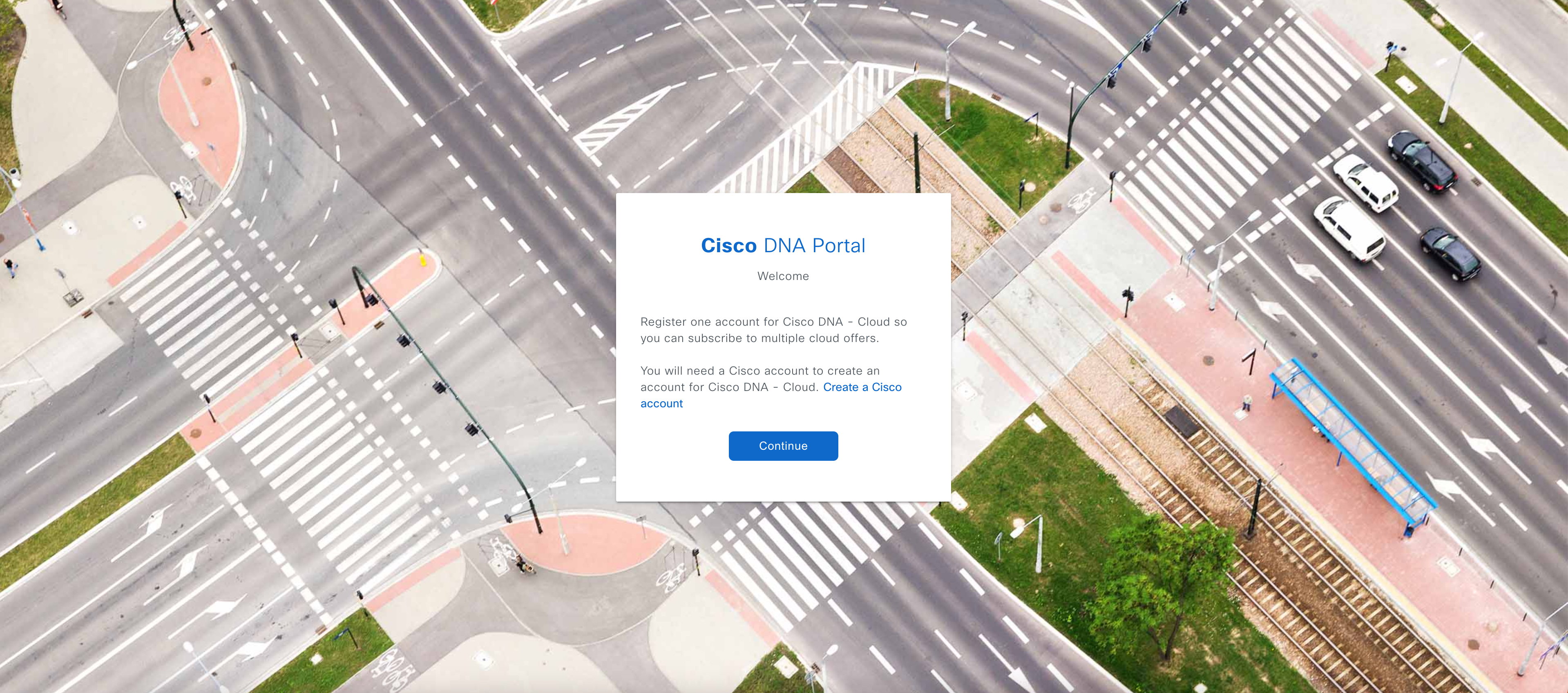 |
|
Step 4 |
On the Create Account window, complete the required fields and then click Register. 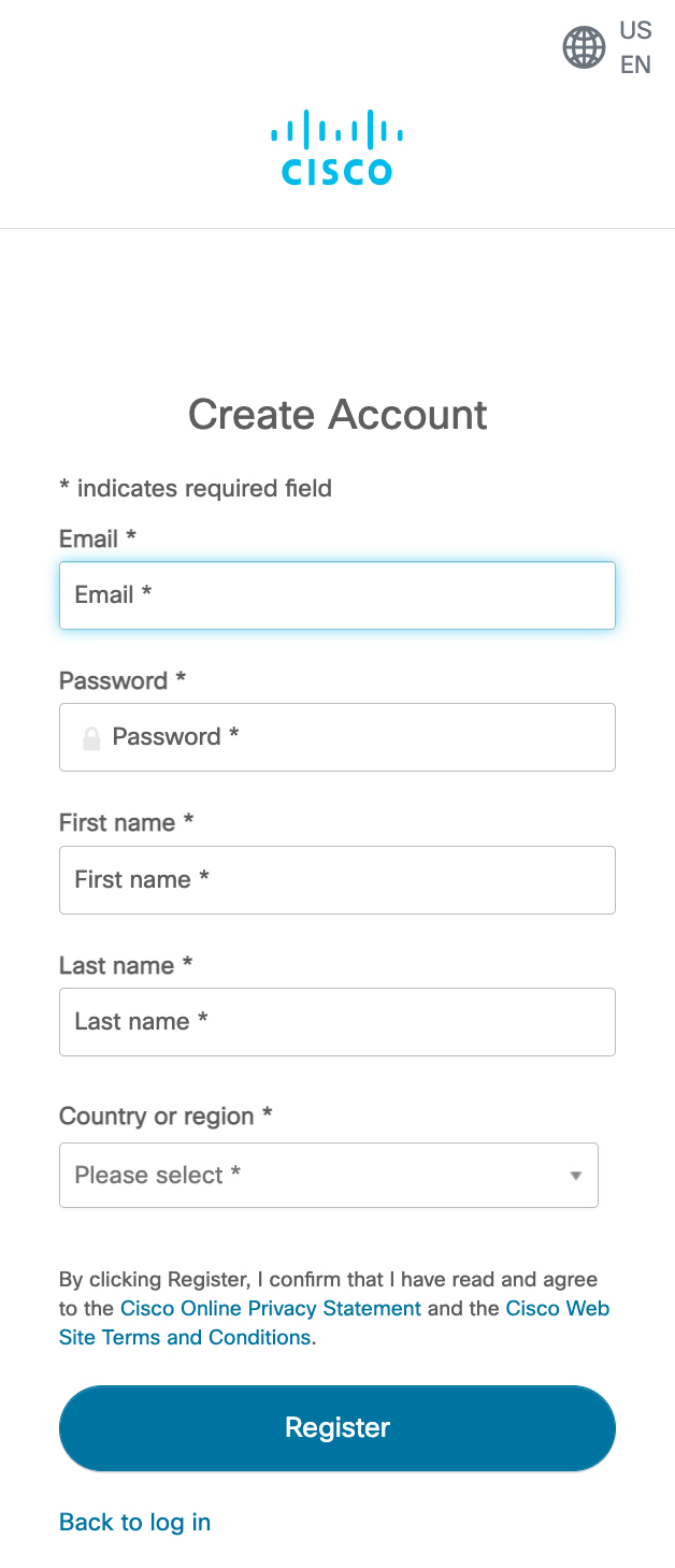 |
|
Step 5 |
Verify your account by going to the email that you registered your account with and clicking Activate Account. 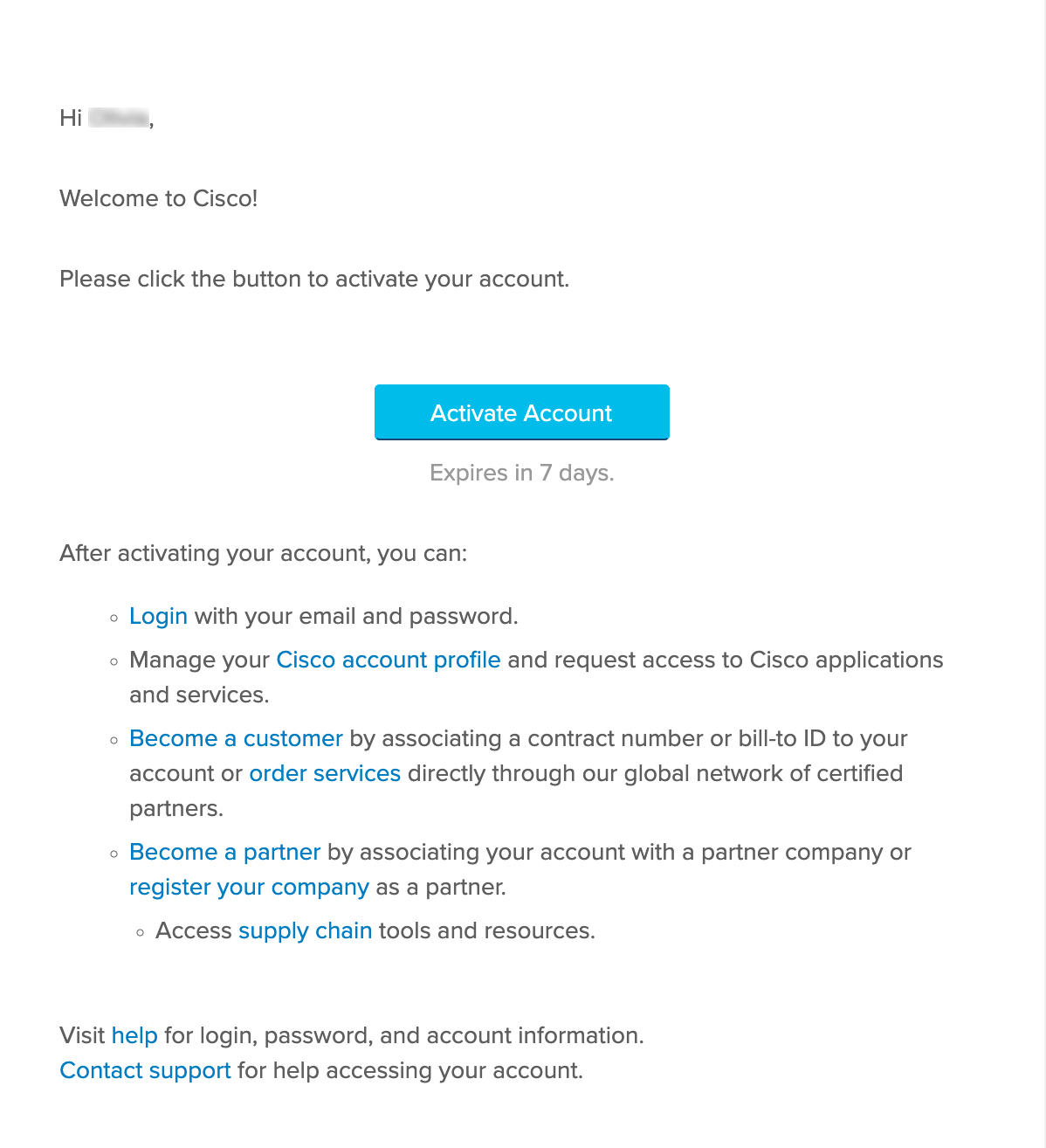 |
Create a Cisco DNA Portal Account
To access Cisco Global Launchpad through Cisco DNA Portal, you must create a Cisco DNA Portal account.
Before you begin
Make sure that you have a Cisco account. For more information, see Create a Cisco Account.
Procedure
|
Step 1 |
In your browser, enter: dna.cisco.com The Cisco DNA Portal login window is displayed.  |
|
Step 2 |
Click Log In With Cisco. |
|
Step 3 |
Enter your Cisco account's email in the Email field, and click Next. 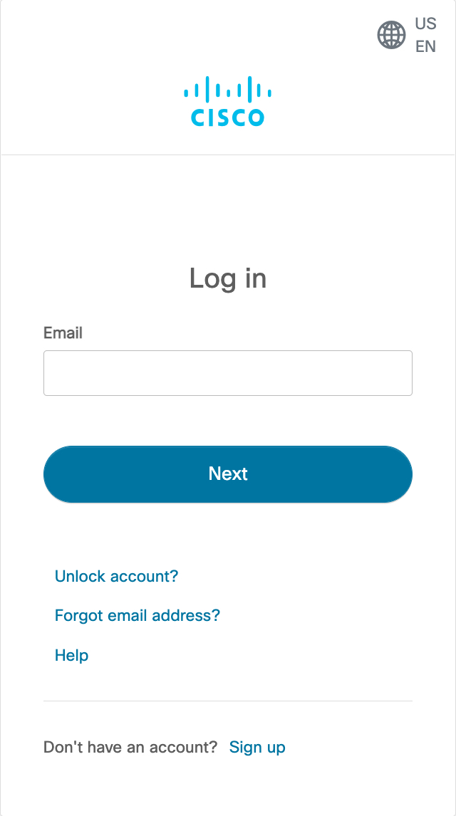 |
|
Step 4 |
Enter your Cisco account's password in the Password field. 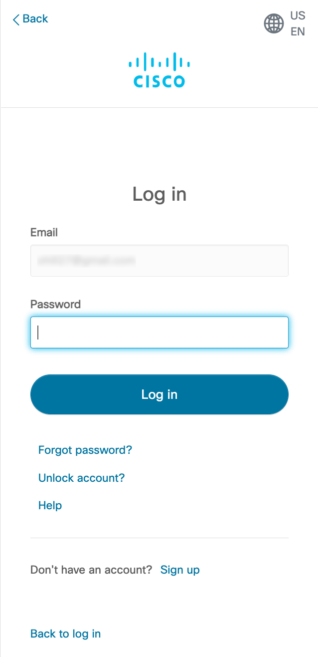 |
|
Step 5 |
Click Log in. |
|
Step 6 |
On the Cisco DNA Portal Welcome window, enter the name of your organization or team in the Name your account field. Then click Continue. 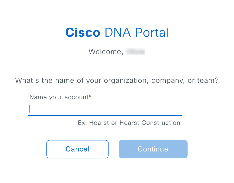 |
|
Step 7 |
On the Cisco DNA Portal Confirm CCO Profile window, do the following: |
Log In to the Cisco DNA Portal with Cisco
To access Cisco Global Launchpad through Cisco DNA Portal, you must log in to Cisco DNA Portal.
Before you begin
Make sure that you have a Cisco account and a Cisco DNA Portal account. For more information, see Create a Cisco Account and Create a Cisco DNA Portal Account.
Procedure
|
Step 1 |
In your browser, enter: dna.cisco.com The Cisco DNA Portal login window is displayed.  |
|
Step 2 |
Click Log In With Cisco. |
|
Step 3 |
Enter your Cisco account's email in the Email field, and click Next.  |
|
Step 4 |
Enter your Cisco account's password in the Password field.  |
|
Step 5 |
Click Log in. If you have only one Cisco DNA Portal account, the Cisco DNA Portal home page is displayed. |
|
Step 6 |
(Optional) If you have multiple Cisco DNA Portal accounts, choose the account that you want to log in to by clicking the account's adjacent Continue button. 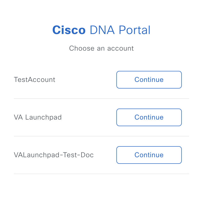 The Cisco DNA Portal home page is displayed. 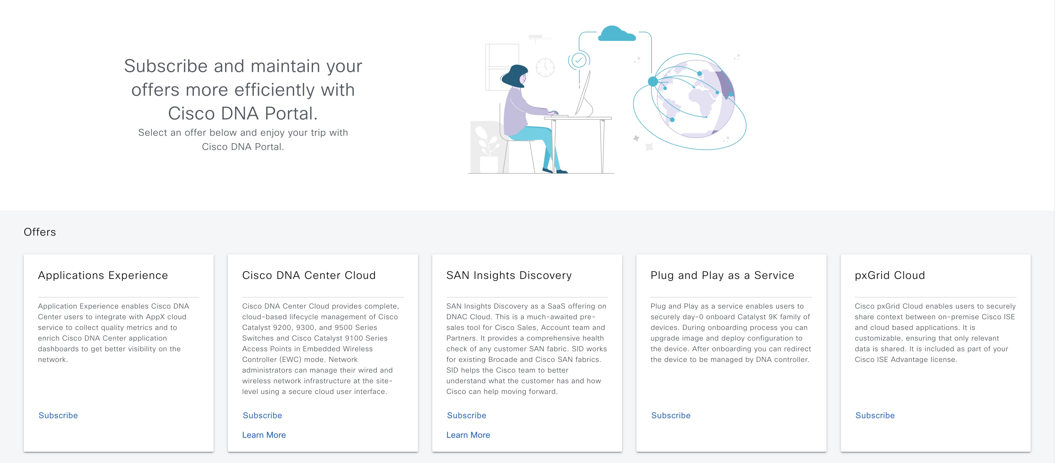 |
Log In to Cisco Global Launchpad
The Cisco Global Launchpad supports the following authentication methods:
-
Log In Using IAM: This method uses the credentials from your Cisco account.
-
Log In Using Federated Identity: Federated access ensures that an identity provider (IdP), such as your organization, is responsible for user authentication and sending information to Cisco Global Launchpad to help determine the scope of resource access to be granted after login. For the first-time login, the user will have an admin user role, which creates the CiscoDNACenter role. The admin can assign this role to subsequent users. The CiscoDNACenter role has the same permissions as the CiscoDNACenter user group. For details about the permissions granted by this role, see the Cisco Catalyst Center on AWS Deployment Guide.
You can use the saml2aws CLI or the AWS CLI to generate tokens to log in to Cisco Global Launchpad as a federated user. For information, see the following topics:
 Note |
Cisco Global Launchpad does not store your AWS credentials. |
Log In Using IAM
This procedure shows you how to log in to Cisco Global Launchpad using identity and access management (IAM). If your company uses MFA, you can choose to log in using this method.
 Note |
Do not open the application in more than one browser tab, in multiple browser windows, or in multiple browser applications at the same time. |
Before you begin
Make sure the following requirements are met:
-
Your AWS account has the administrator access permission assigned to it.
-
Cisco Global Launchpad is installed or you have access to the hosted Cisco Global Launchpad.
-
You have your AWS Access Key ID and Secret Access Key on hand.
-
If your company uses multifactor authentication (MFA), MFA needs to be set up in AWS before you log in. For information, see the Enabling a virtual multi-factor authentication (MFA) device (console) topic in the AWS documentation.
Procedure
|
Step 1 |
Under the AWS logo, click the IAM Login radio button. 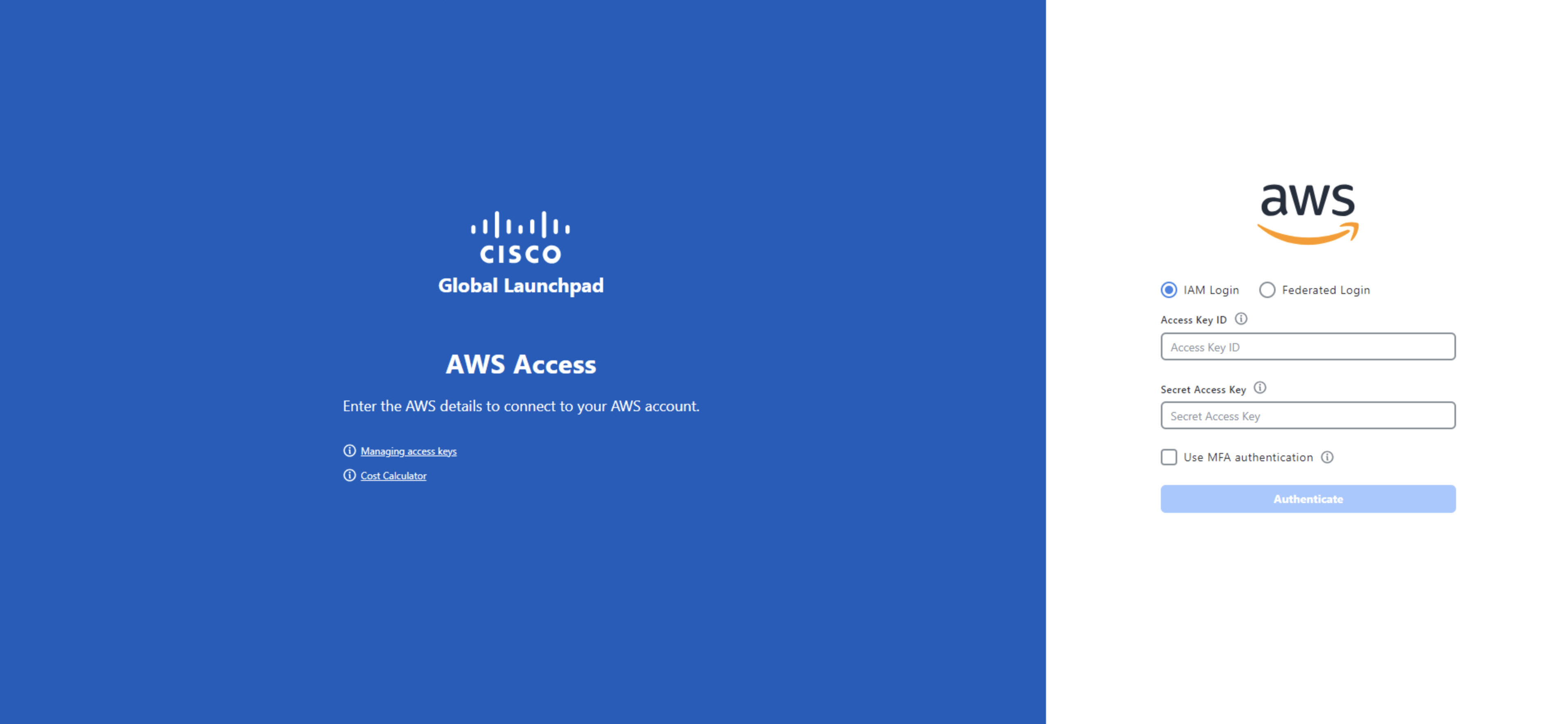 |
|
Step 2 |
Enter your credentials in the fields. For information about how to get an Access Key ID and Secret Access Key, see the AWS Managing access keys topic in the AWS Identity and Access Management User Guide on the AWS website. 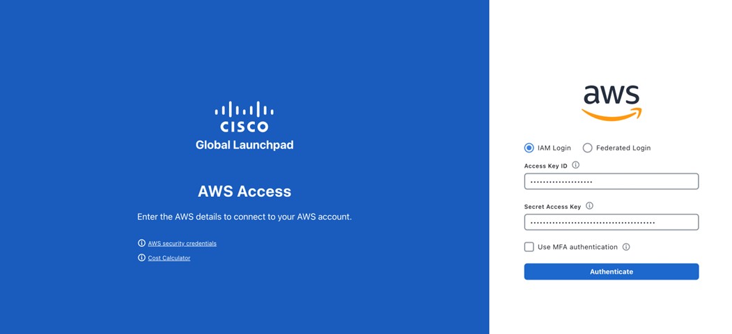 |
|
Step 3 |
(Optional) If your company uses MFA, click the Use MFA authentication check box. 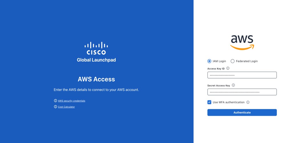 |
|
Step 4 |
Click Authenticate. If you are logging in with MFA, choose your MFA device from the drop-down list and enter your MFA passcode. 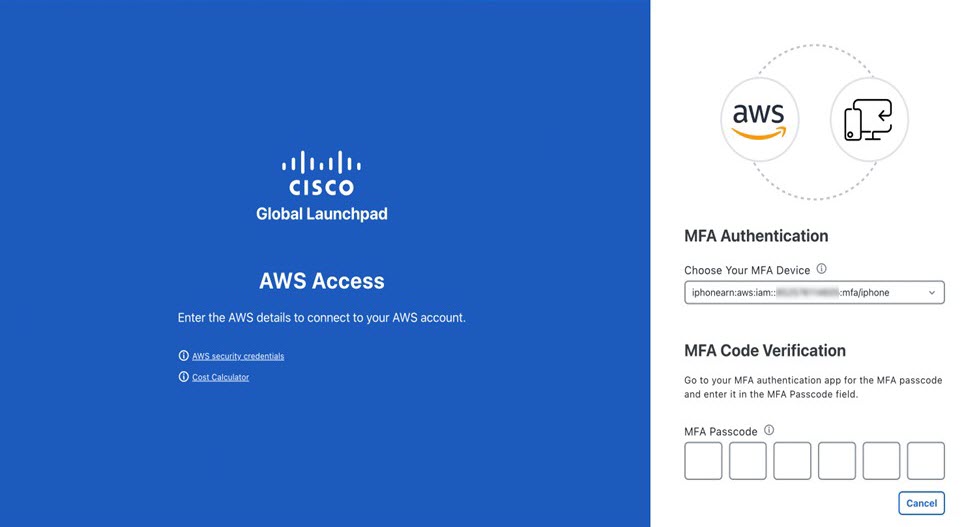 After logging in successfully, the Login Status screen is displayed. This page displays the statuses of various operations that the system performs when you log in. Then the Dashboard pane is displayed and the us-east-1 region is selected by default. |
|
Step 5 |
If you're prompted to update the region version, follow the prompts to complete the update. |
|
Step 6 |
If you encounter any login errors, you need to resolve them and log in again. |
Log In Using Federated Identity
This procedure shows you how to log in to Cisco Global Launchpad using a federated identity.
 Note |
Do not open the application in more than one browser tab, in multiple browser windows, or in multiple browser applications at the same time. |
Before you begin
Make sure the following requirements are met:
-
Your AWS account has the administrator access permission assigned to it.
-
Cisco Global Launchpad is installed or you have access to the hosted Cisco Global Launchpad.
-
You have your AWS Account ID, Access Key ID, and Secret Access Key on hand. For information about how to obtain these credentials, see Generate Federated User Credentials Using saml2aws or Generate Federated User Credential Using AWS CLI.
Procedure
|
Step 1 |
From a browser window, do one of the following:
The AWS login window is displayed.  |
|
Step 2 |
Under the AWS logo, click the Federated Login radio button. 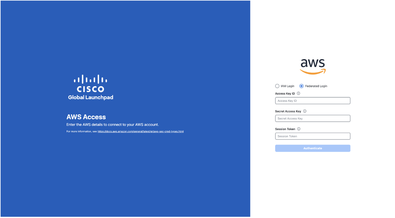 |
|
Step 3 |
Enter your credentials in the fields. For more information, see Generate Federated User Credentials Using saml2aws or Generate Federated User Credential Using AWS CLI. |
|
Step 4 |
Click Authenticate. After you log in successfully, the Login Status screen is displayed. This page displays the statuses of various operations that the system performs when you log in. Then the Dashboard pane is displayed and the us-east-1 region is selected by default. |
|
Step 5 |
If you're prompted to update the region version, follow the prompts to complete the update. |
|
Step 6 |
If you encounter any login errors, you must resolve them and log in again. |
Generate Federated User Credentials Using saml2aws
You can generate temporary AWS credentials using a Command Line Interface (CLI) tool and use the generated credentials to log in to Cisco Global Launchpad.
Procedure
|
Step 1 |
From the CLI, install saml2aws. For information, see the detailed instructions on Github. |
|
Step 2 |
Verify the installation by entering saml2aws. If the installation is successful, the following output is displayed: 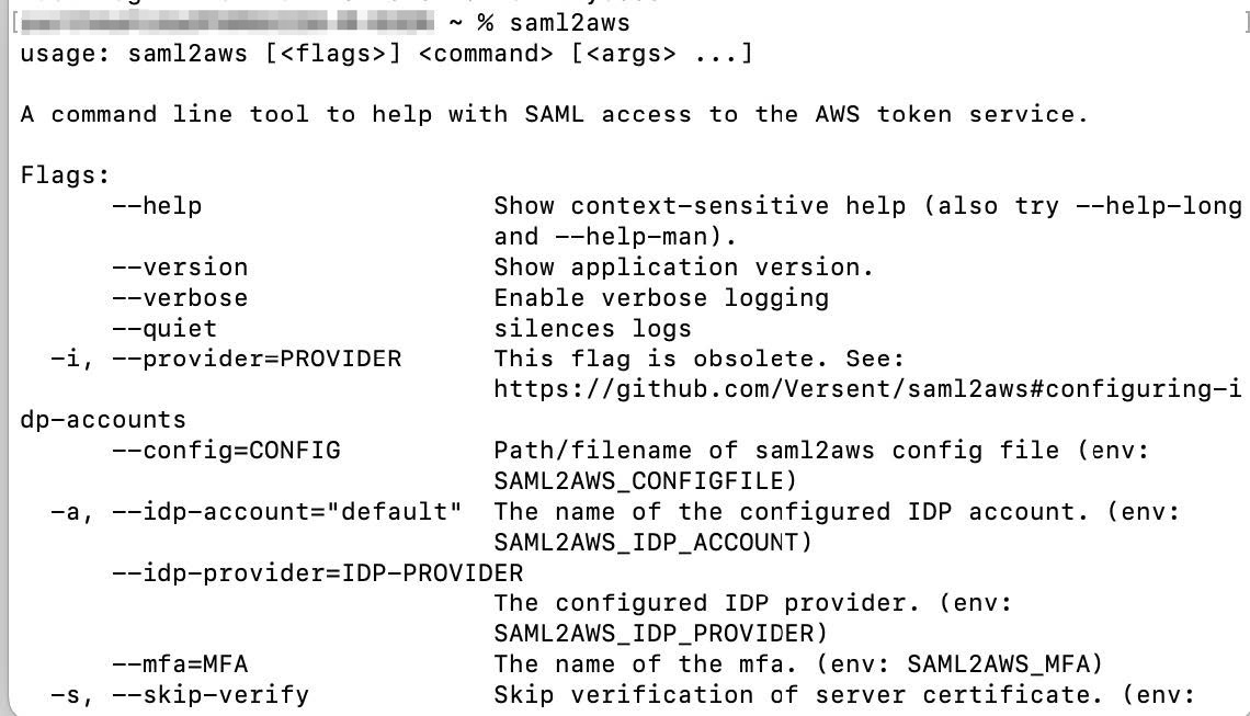 |
|
Step 3 |
Configure your account. |
|
Step 4 |
Generate your federated credentials. Your credentials are generated and stored in ~/aws/credentials. |
|
Step 5 |
Download the credentials by entering saml2aws script. |
|
Step 6 |
Note the values of the following parameters as you will use them to log in to Cisco Global Launchpad as a federated user:
|
|
Step 7 |
On the Cisco Global Launchpad login window, select Federated Login and enter the generated credentials in the corresponding fields. 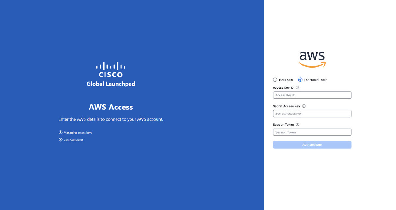 |
Generate Federated User Credential Using AWS CLI
You can generate temporary AWS credentials using the AWS Command Line Interface (CLI) and use these credentials to log in to Cisco Global Launchpad.
Procedure
|
Step 1 |
In a browser window, navigate to the AWS Single Sign On (SSO)/Active Directory (AD) window. |
||
|
Step 2 |
In the AWS Single Sign On (SSO)/Active Directory (AD) window, click the AWS Console link. The following window is displayed. 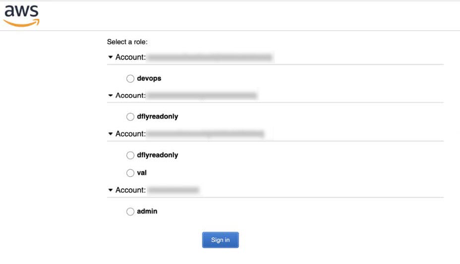 |
||
|
Step 3 |
Right-click anywhere in the window, and from the drop-down menu, choose Inspect Element or Inspect (depending on the browser).
The Developer Tools panel is displayed, similar to the following window. 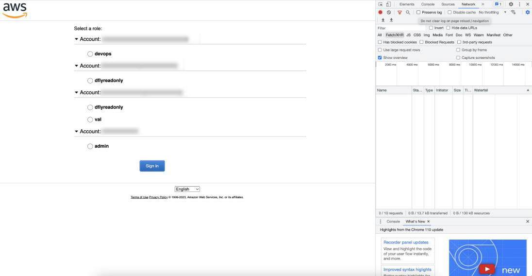 |
||
|
Step 4 |
In the Developer Tools panel, click the Network tab and check the Preserve Log check box. (This option can be found on the tool panel, right beside the Magnifying Glass icon.) |
||
|
Step 5 |
In the AWS Console, click Sign In. |
||
|
Step 6 |
In the Developer Tools panel, filter the required API calls by entering saml in the Filter field. 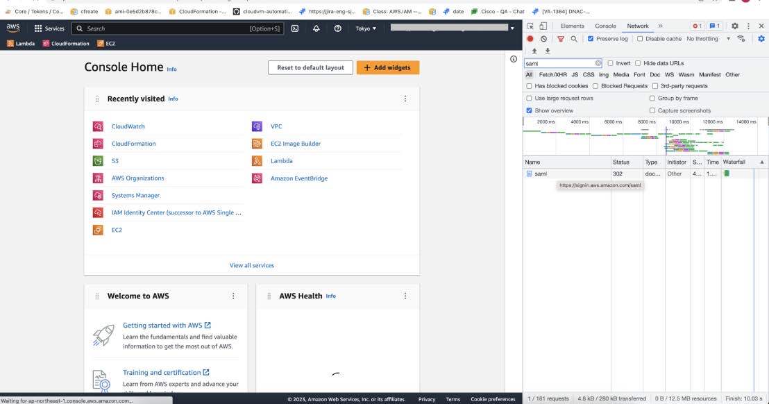 |
||
|
Step 7 |
Click the API request named saml. |
||
|
Step 8 |
Click the Payload tab. The saml API response is displayed under the Form Data tab. 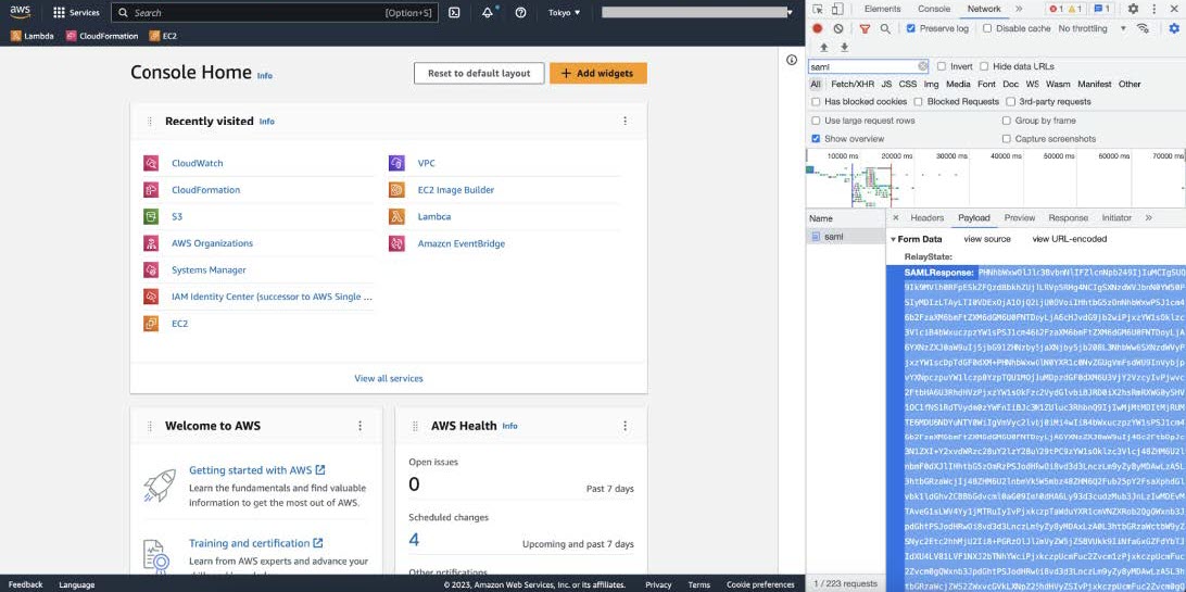 |
||
|
Step 9 |
Copy the value of the SAML response.
|
||
|
Step 10 |
Navigate to your AWS Console, choose , and select your IdP. 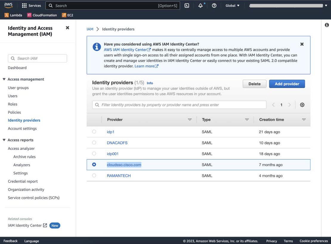 |
||
|
Step 11 |
Obtain the following details for your IdP:
|
||
|
Step 12 |
From the AWS CLI, enter the following command: aws sts assume-role-with-saml --role-arn <Role-Arn> --principal-arn <IDP-Arn> --saml-assertion <SAML response>
The variables in this command refer to the values obtained earlier, as follows:
For example:
Output similar to the following output is displayed: |
||
|
Step 13 |
Note the values of the following generated credentials:
|
||
|
Step 14 |
On the Cisco Global Launchpad login window, select Federated Login and enter the generated credentials from Step 13 in the corresponding fields.  |
Create a New VA Pod
A VA pod is the AWS hosting environment for the Catalyst Center VA. The hosting environment includes AWS resources, such as the Catalyst Center VA EC2 instance, Amazon Elastic Block Storage (EBS), backup NFS server, security groups, routing tables, Amazon CloudWatch logs, Amazon Simple Notification System (SNS), VPN Gateway (VPN GW), TGW, and so on.
Using Cisco Global Launchpad, you can create multiple VA pods—one VA pod for each Catalyst Center VA.
 Note |
|
This procedure guides you through the steps to create a new VA pod.
Before you begin
Your AWS account must have administrator access permission to perform this procedure. For information, see Prerequisites for Automated Deployment.
Procedure
|
Step 1 |
If you are an admin user logging in for the first time, enter your email address in the Email ID field and click Submit. If you are a subuser, proceed to Step Create a New VA Pod. 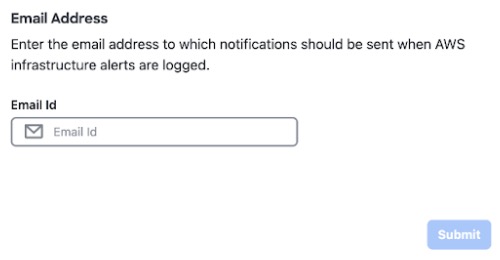 You can subscribe to the Amazon SNS to receive alerts about deployed resources, changes, and resource over-utilization. Further, alarms can be set up to notify you if Amazon CloudWatch detects any unusual behavior in Cisco Global Launchpad. In addition, AWS Config evaluates and assesses your configured resources and sends audit logs of the results as well. For more information, see "Subscribe to the Amazon SNS Email Subscription" and "View Amazon CloudWatch Alarms" in the Cisco Global Launchpad Administrator Guide. After you enter your email, several processes happen:
After you log in successfully, the Dashboard pane is displayed.
|
||||
|
Step 2 |
Click + Add a VA pod. 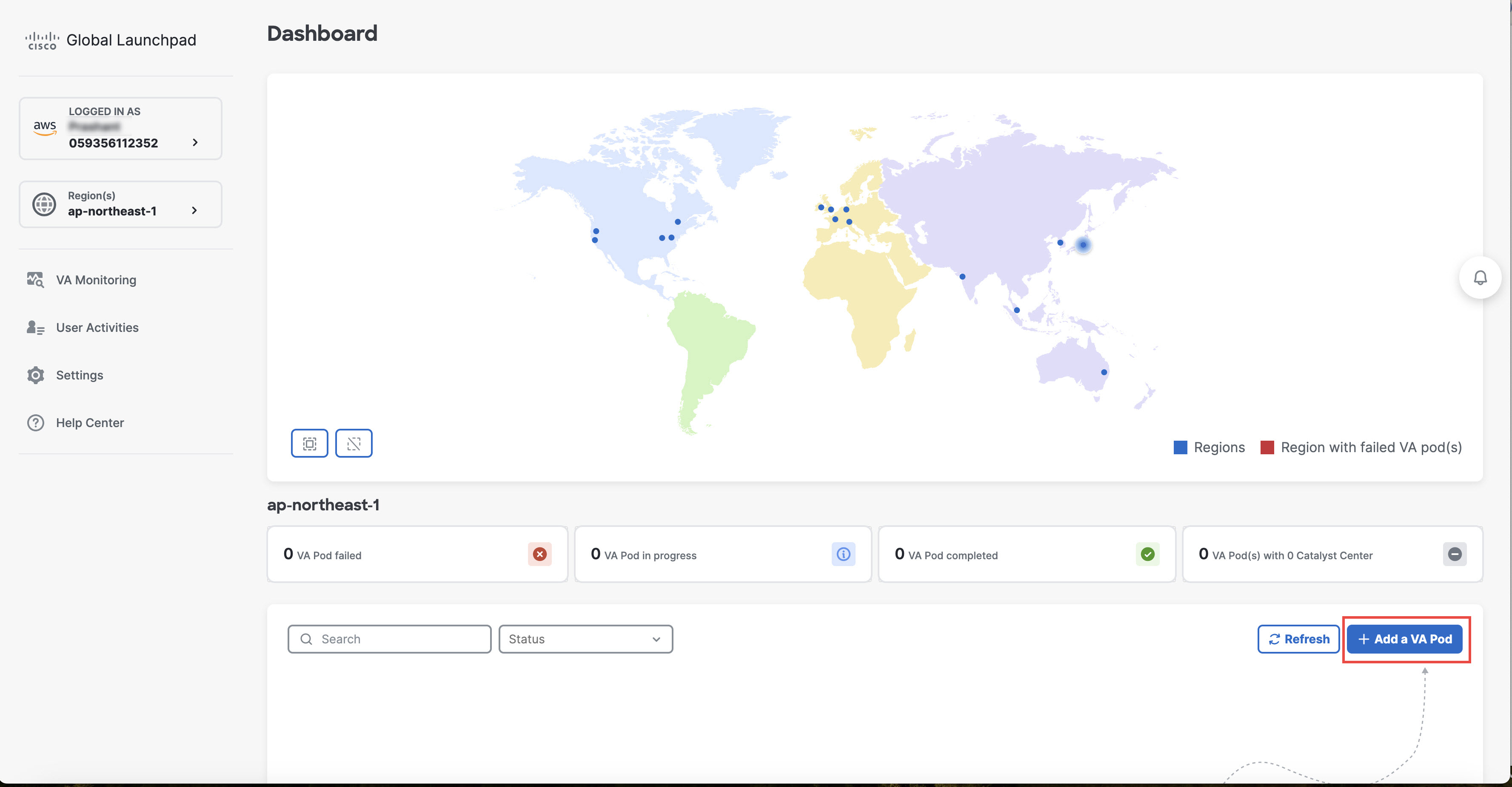 |
||||
|
Step 3 |
Configure the AWS infrastructure, which includes the region, VPC, private subnet, routing table, security group, virtual gateway, and CGW, by completing the following steps: |
||||
|
Step 4 |
Download the on-premises configuration file by completing the following steps: |
||||
|
Step 5 |
Check the status of your network configuration based on the on-premises connectivity preferences that you selected during the AWS infrastructure configuration by completing one of the following actions:
|
||||
|
Step 6 |
Click Go to dashboard to return to the Dashboard pane, where you can create more VA pods and manage your existing ones. |
Manually Configure Routing on Your Existing Gateway or Direct Connect Attachment
If you selected Existing Transit Gateway and Existing Attachments as your preferred connectivity option while creating a new VA pod, Cisco Global Launchpad creates a VPC to launch Catalyst Center and attaches this VPC to your existing TGW.
For Cisco Global Launchpad to establish the TGW connection, you must manually configure the TGW routing table on AWS and add the routing configuration of your existing CGW or direct connect attachment.
Procedure
|
Step 1 |
From the AWS console, go to VPC service. |
|
Step 2 |
In the left navigation pane, under Transit Gateways, choose Transit gateway route tables and select the existing TGW route table. |
|
Step 3 |
In the Transit gateway route tables window, click the Associations tab, choose the attachment to associate from the drop-down list, and then click Create association. The association can be your existing CGW or direct connect attachment. 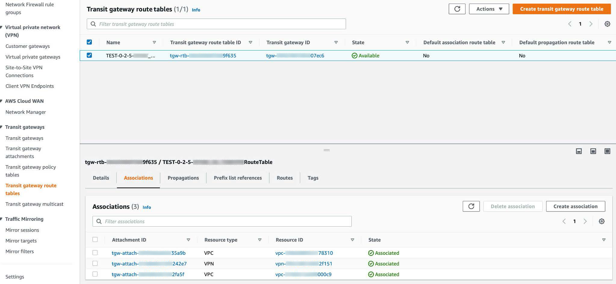 |
|
Step 4 |
In the Transit gateway route tables window, click the Propagations tab and then click Create propagation. 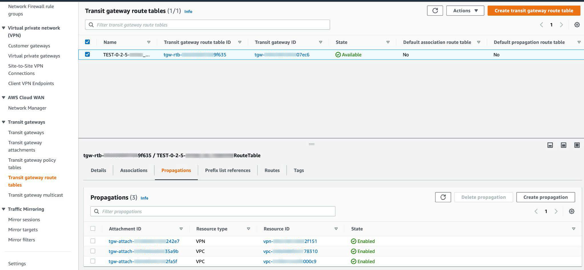 |
|
Step 5 |
To ensure that the static route between the respective VPC and VPN is active, click the Routes tab and then click Create static route. |
|
Step 6 |
Ensure that your on-premises router configuration is updated to route the network traffic destined for the CIDR ranges that are allocated to your CGW or direct connect attachment in your AWS environment. For example: |
Create a New Catalyst Center
Use this procedure to configure a new Catalyst Center VA.
Procedure
|
Step 1 |
In the Dashboard pane, below the map, locate the VA pod where you want to create your Catalyst Center VA. 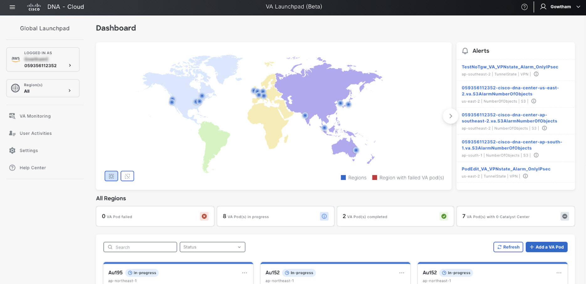 |
||||
|
Step 2 |
In the VA pod card, click Create/Manage Catalyst Center(s).  |
||||
|
Step 3 |
In the VA Pod Dashboard pane, click + Create a new Catalyst Center. 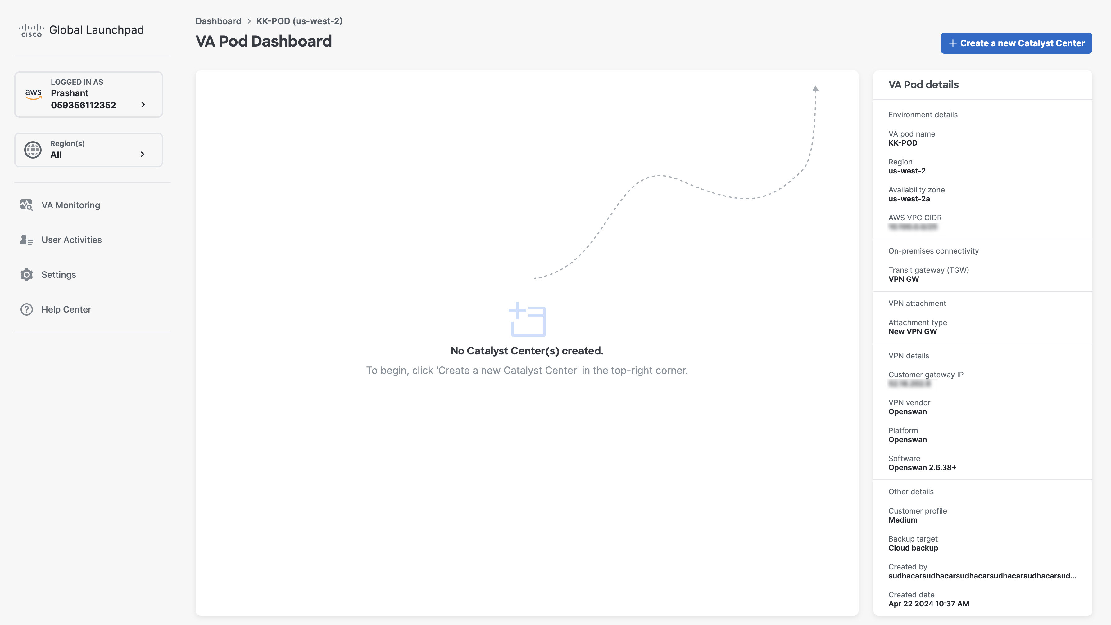 |
||||
|
Step 4 |
Enter the following details:
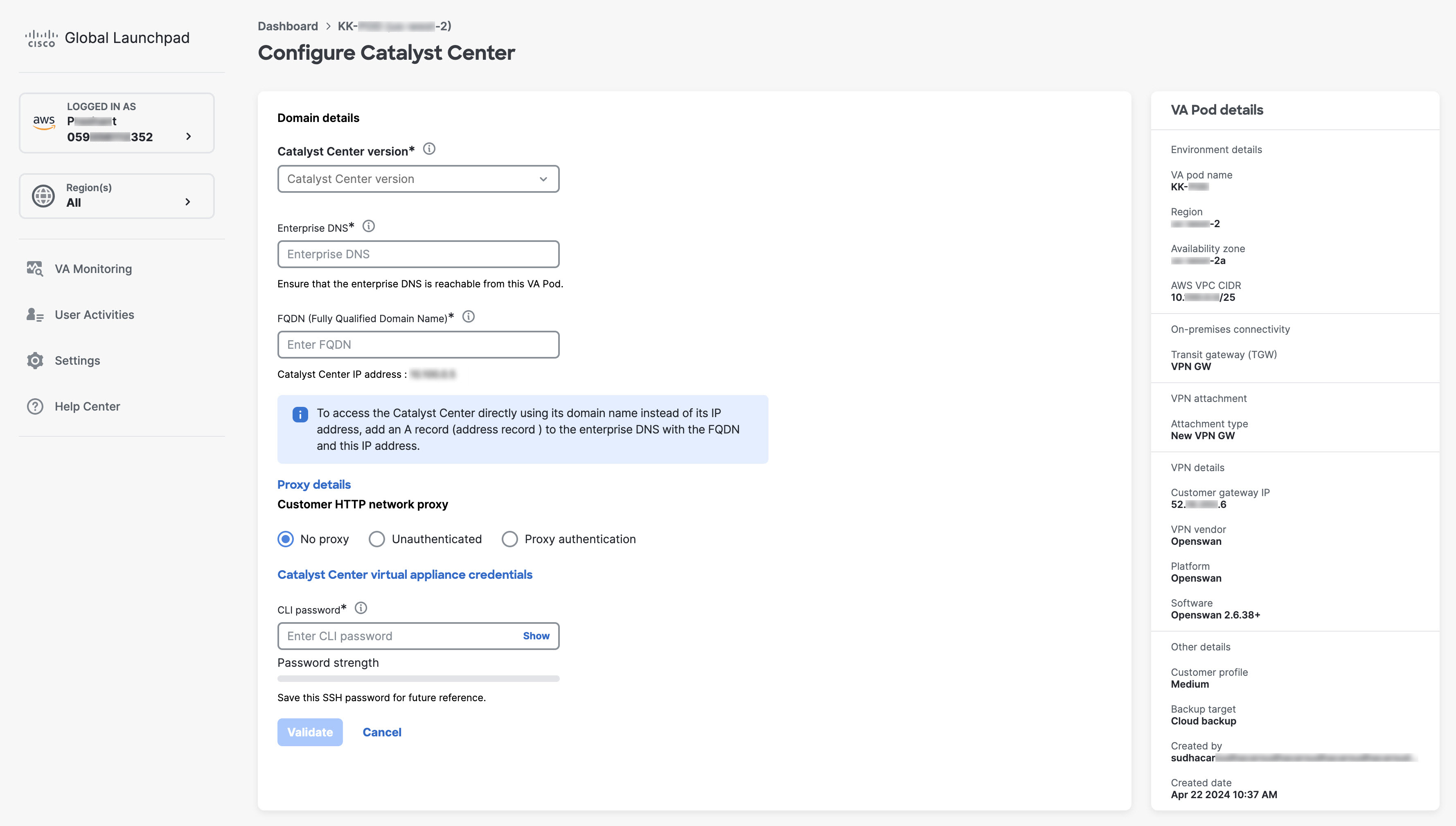 |
||||
|
Step 5 |
Click Validate to validate the Enterprise DNS server and FQDN configured on the DNS server.
|
||||
|
Step 6 |
In the Summary window, review the configuration details.
 |
||||
|
Step 7 |
If you're satisfied with the configuration, click Generate PEM key file. |
||||
|
Step 8 |
In the Download PEM key file dialog box, click Download PEM key file. If you click Cancel, you're returned to the Summary window.
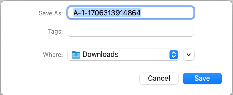 |
||||
|
Step 9 |
After you downloaded the PEM file, click Start Catalyst Center configuration. 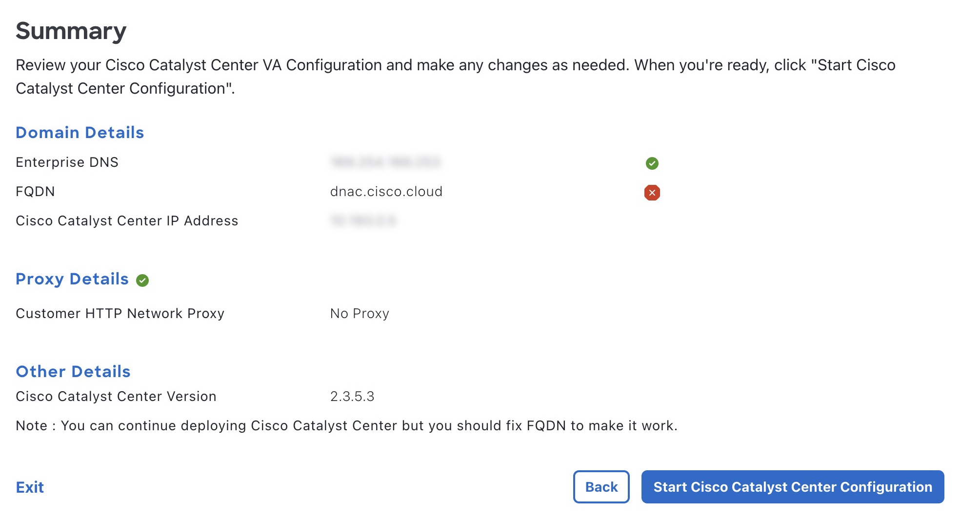 Cisco Global Launchpad configures the Catalyst Center VA environment. After the environment is configured, Catalyst Center VA boots. Initially, Cisco Global Launchpad displays the outer ring in gray. When Port 2222 is validated, the image turns amber. When Port 443 is validated, the image
turns green.
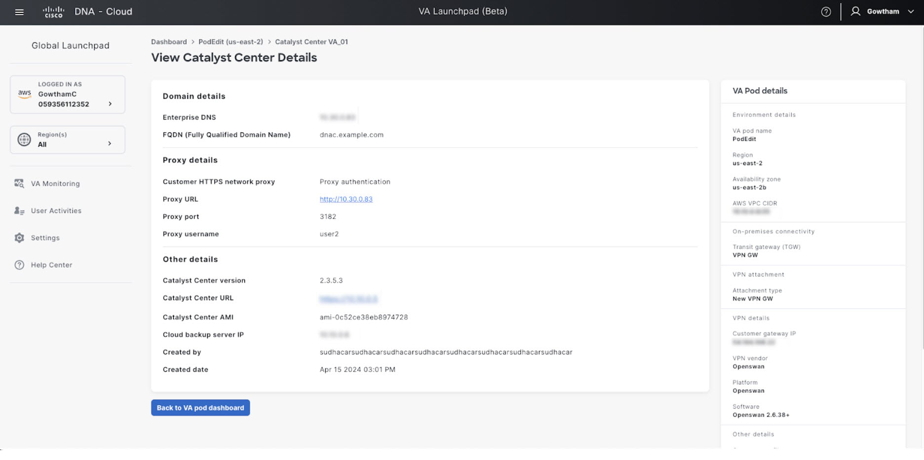
After Catalyst Center VA is done booting, the configuration is complete. You can now view your Catalyst Center VA details. 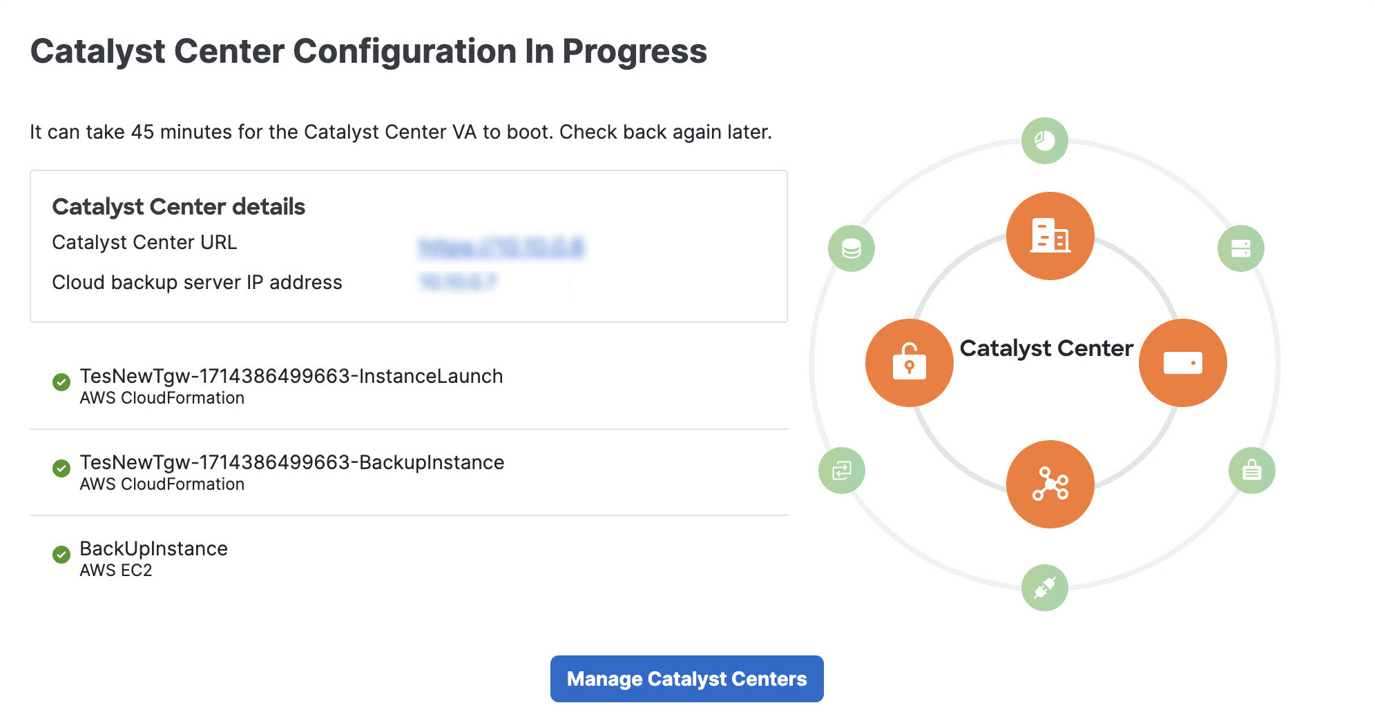
If the configuration fails, exit to the VA pod dashboard pane. For information, see Troubleshoot Catalyst Center VA Configuration Errors. 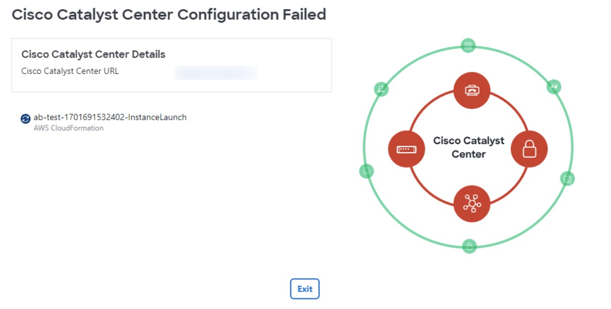 |
||||
|
Step 10 |
To return to the VA Pod Dashboard pane, click Back to VA Pod dashboard. |
Use AWS CloudFormation to Manually Deploy Catalyst Center on AWS
If you're familiar with AWS administration, you have the option of deploying the Catalyst Center AMI manually on your AWS account using AWS CloudFormation.
With this method, you need to create the AWS infrastructure, establish a VPN tunnel, and deploy Catalyst Center.
Deploy Catalyst Center on AWS Manually Using AWS CloudFormation
You can manually deploy Catalyst Center on AWS using AWS CloudFormation. The provided AWS CloudFormation template contains the relevant details for all required parameters.
Before you begin
-
You have the AWS environment set up with all the required components. For information, see Prerequisites for Manual Deployment Using AWS CloudFormation.
-
The VPN tunnel is up.
Procedure
|
Step 1 |
Depending on which file you want to download, do one of the following:
The TAR file contains the AWS CloudFormation template that you use to create your Catalyst Center VA instance. The AWS CloudFormation template contains several AMIs, each with a different AMI ID based on a specific region. Use the appropriate AMI ID for your region:
|
||||||||||||||||||||||||||||||||||||||||||||||||||||||||||||||||||||||||||||||||||||||||||||||||||||||||||||||||||||||||||||||||||
|
Step 2 |
Verify that the TAR file is genuine and from Cisco. For detailed steps, see Verify the Catalyst Center VA TAR File. |
||||||||||||||||||||||||||||||||||||||||||||||||||||||||||||||||||||||||||||||||||||||||||||||||||||||||||||||||||||||||||||||||||
|
Step 3 |
Log in to the AWS console. The AWS console is displayed. |
||||||||||||||||||||||||||||||||||||||||||||||||||||||||||||||||||||||||||||||||||||||||||||||||||||||||||||||||||||||||||||||||||
|
Step 4 |
In the search bar, enter cloudformation. 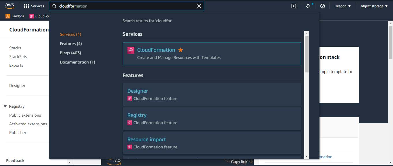 |
||||||||||||||||||||||||||||||||||||||||||||||||||||||||||||||||||||||||||||||||||||||||||||||||||||||||||||||||||||||||||||||||||
|
Step 5 |
From the drop-down menu, choose CloudFormation. |
||||||||||||||||||||||||||||||||||||||||||||||||||||||||||||||||||||||||||||||||||||||||||||||||||||||||||||||||||||||||||||||||||
|
Step 6 |
Click Create stack and choose With new resources (standard). 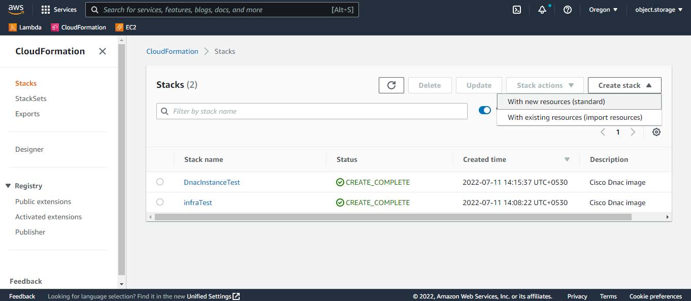 |
||||||||||||||||||||||||||||||||||||||||||||||||||||||||||||||||||||||||||||||||||||||||||||||||||||||||||||||||||||||||||||||||||
|
Step 7 |
Under Specify template, select Upload a template file, and choose the AWS CloudFormation template that you downloaded in Step 1. 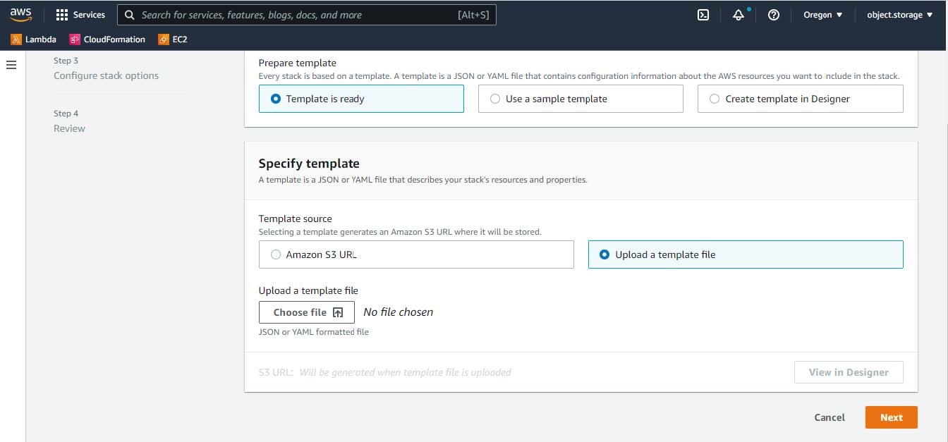 |
||||||||||||||||||||||||||||||||||||||||||||||||||||||||||||||||||||||||||||||||||||||||||||||||||||||||||||||||||||||||||||||||||
|
Step 8 |
Enter a stack name and review the following parameters:
|
||||||||||||||||||||||||||||||||||||||||||||||||||||||||||||||||||||||||||||||||||||||||||||||||||||||||||||||||||||||||||||||||||
|
Step 9 |
(Optional) Click Next to configure the stack options. 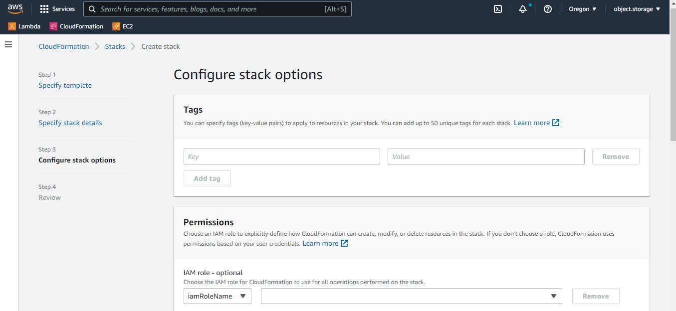 |
||||||||||||||||||||||||||||||||||||||||||||||||||||||||||||||||||||||||||||||||||||||||||||||||||||||||||||||||||||||||||||||||||
|
Step 10 |
Click Next to review your stack information. |
||||||||||||||||||||||||||||||||||||||||||||||||||||||||||||||||||||||||||||||||||||||||||||||||||||||||||||||||||||||||||||||||||
|
Step 11 |
If you are satisfied with the configuration, click Submit to finish. 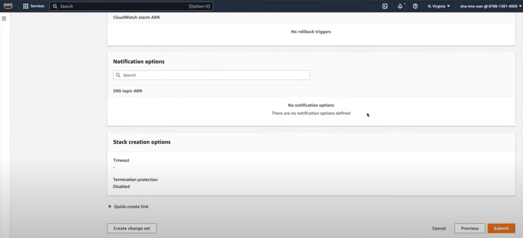 The stack creation process usually takes from 45 to 60 minutes. |
||||||||||||||||||||||||||||||||||||||||||||||||||||||||||||||||||||||||||||||||||||||||||||||||||||||||||||||||||||||||||||||||||
Validate the Deployment
To ensure that your environment setup and Catalyst Center VA configuration are working, perform the following validation checks.
Before you begin
Ensure that your stack creation on AWS CloudFormation has no errors.
Procedure
|
Step 1 |
From the Amazon EC2 console, validate the network and system configuration and verify that the Catalyst Center IP address is correct. |
|
Step 2 |
Send a ping to the Catalyst Center IP address to ensure that your host details and network connection are valid. |
|
Step 3 |
Establish an SSH connection with Catalyst Center to verify that Catalyst Center is authenticated. |
|
Step 4 |
Test HTTPS accessibility to the Catalyst Center GUI using one of the following methods:
|
Use AWS Marketplace to Manually Deploy Catalyst Center on AWS
If you're familiar with AWS administration, you have the option of deploying Catalyst Center manually on your AWS account using AWS Marketplace.
Deploy Catalyst Center on AWS Manually Using AWS Marketplace
For instructions on how to deploy Catalyst Center on AWS using AWS Marketplace, do one of the following:
-
Go to the Cisco Software Download site and download the following file:
Deploy-cisco-dna-center-using-aws-marketplace-2.0.0.tar.gz
Validate the Deployment
To ensure that your environment setup and Catalyst Center VA configuration are working, perform the following validation checks.
Before you begin
Ensure that your stack creation on AWS Marketplace has no errors.
Procedure
|
Step 1 |
From the Amazon EC2 console, validate the network and system configuration and verify that the Catalyst Center IP address is correct. |
|
Step 2 |
Send a ping to the Catalyst Center IP address to ensure that your host details and network connection are valid. |
|
Step 3 |
Establish an SSH connection with Catalyst Center to verify that Catalyst Center is authenticated. |
|
Step 4 |
Test HTTPS accessibility to the Catalyst Center GUI using one of the following methods:
|
Post-Installation Tasks
Subscribe to the Amazon SNS Email Subscription
To receive email notifications from Amazon Simple Notification System (SNS), you can subscribe to the Amazon SNS email subscription in Cisco Global Launchpad settings. Amazon SNS sends AWS alerts about deployed resources, changes, or resource over-utilization to the provided email.
Procedure
|
Step 1 |
In the left navigation pane, click the settings icon ( |
||
|
Step 2 |
In the Settings pane, in the Email to notify area, enter the preferred email address in the Email ID field. 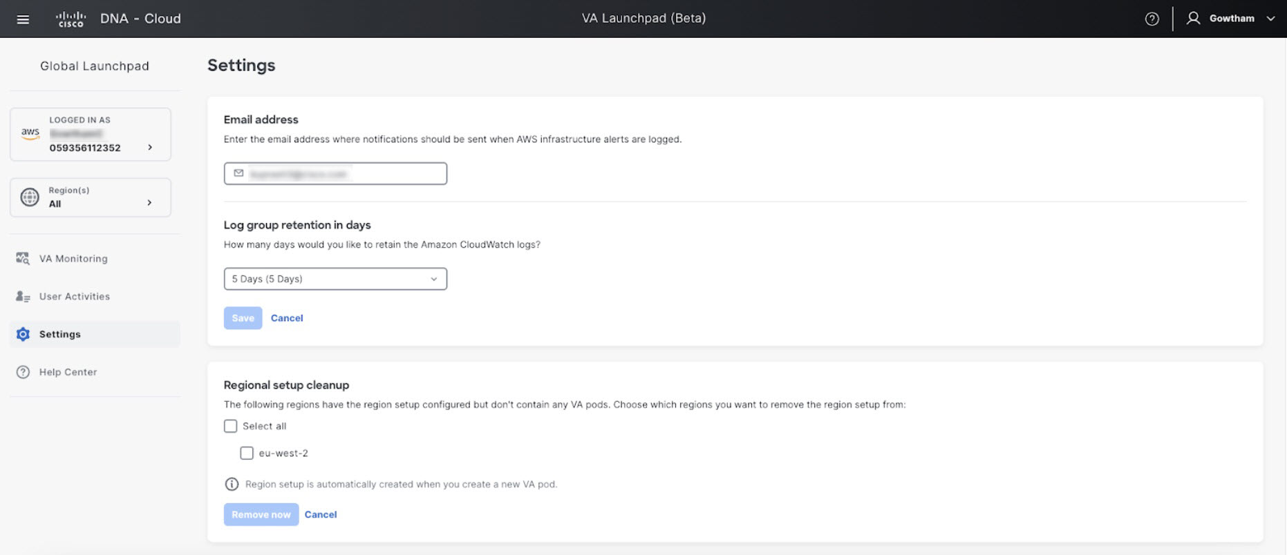 When you update an email ID, the old email address is unsubscribed and the new email address is subscribed. Alerts about VA pods that are created after the email change are sent to the new email address. Alerts about existing VA Pods are not sent to the new email address. If an existing user account has not confirmed their email subscription and updates their subscription with a new email address, both the old and new email addresses are subscribed and remain configured in Amazon SNS.
|
||
|
Step 3 |
Click Save. |
Configure Log Retention
You can set the number of days to keep Amazon CloudWatch logs. By default, the logs are kept indefinitely.
Procedure
|
Step 1 |
In the left navigation pane, click the settings icon ( The Settings pane is displayed.  |
|
Step 2 |
Under Log Group Retention In Days, click the Select Log Group Retention In Days drop-down list and choose a retention period for the Amazon CloudWatch logs. |
|
Step 3 |
Click Save. |
Cisco Prime Infrastructure to Catalyst Center Migration
This section provides an overview on how to migrate from Cisco Prime Infrastructure to Catalyst Center. Migration involves two steps—the first step is to conduct a readiness check followed by the second step to migrate the sites and devices to Catalyst Center. For information on how to use the Catalyst Center readiness tool for Cisco Prime Infrastructure (PDART), see Use PDART - a Cisco Catalyst Center Readiness Tool.
After assessing the migration readiness, the Prime Data Migration Tool (PDMT) can be used to migrate data from Cisco Prime to Catalyst Center. You can download the tool from here. For more information on the migration process, see Validated Profile: Cisco Prime Infrastructure to Cisco Catalyst Center Migration.
For information on compatibility of the PDMT versions with Catalyst Center releases, see Cisco Prime Infrastructure and Cisco Catalyst Center Compatibility Matrix.
Multiple Catalyst Centers—Limited Availability
Multiple Catalyst Center allows you to define a single global set of virtual networks for software-defined access across multiple Catalyst Center clusters integrated with a single Cisco ISE system. This Multiple Catalyst Center functionality is a Limited Availability offering in Catalyst Center on ESXi.
To facilitate global administration of Cisco SD-Access across multiple Catalyst Center clusters with a consistent set of virtual networks, the Multiple Catalyst Center feature leverages the existing secure connection with Cisco ISE to propagate virtual networks, Security Group Tags (SGTs), access contracts, and Group-Based Access Control (GBAC) Policy from one cluster to another cluster, all integrated with the same Cisco ISE deployment. Cisco ISE takes the information learned from one cluster (the Author node) and propagates it to the other clusters (Reader nodes).
Because there are significant caveats for the Multiple Catalyst Center functionality, the Cisco SD-Access Design Council reviews the requests and provides guidance for use of the Multiple Catalyst Center to participants in the Limited Availability program.
Contact your account team to submit a request to the Cisco SD-Access Design Council to participate in the Limited Availability program.
Customers who are using Cisco ISE Version 3.1 or earlier must request and install the Limited Availability package before enabling Multiple Catalyst Center.
 Note |
After this functionality is enabled, it can be disabled only by deleting Cisco ISE. In addition, if this functionality is enabled, because pxGrid is a required component of the solution, pxGrid cannot be disabled subsequently. |
Deploy Cisco ISE on AWS
The following sections describe how to deploy Cisco ISE on AWS.
Launch a Cisco ISE CloudFormation Template Through AWS Marketplace
This method may launch standalone Cisco ISE instances only. To create a Cisco ISE deployment, see the Chapter "Deployment" in the Cisco ISE Administrator Guide for your release.
 Note |
|
The Cisco ISE CFT creates an instance of the General Purpose SSD (gp2) volume type.
 Note |
From Cisco ISE Release 3.4, OpenAPI services are enabled automatically, and hence, there's no need to send OpenAPI-related options while launching an instance. |
Before you begin
In AWS, create the security groups and management networks that you want to include in your Cisco ISE CFT configuration.
Procedure
|
Step 1 |
Log in to the Amazon Management Console at https://console.aws.amazon.com/, and search for AWS Marketplace Subscriptions. |
||||||||||
|
Step 2 |
In the Manage Subscriptions window that is displayed, click Discover Products in the left pane. |
||||||||||
|
Step 3 |
Enter Cisco Identity Services Engine (ISE) in the search bar.
|
||||||||||
|
Step 4 |
Click the product name. |
||||||||||
|
Step 5 |
In the new window that is displayed, click Continue to Subscribe.
|
||||||||||
|
Step 6 |
Click Continue to Configuration. |
||||||||||
|
Step 7 |
In the Configure this software area, click Learn More and then click Download CloudFormation Template to download the Cisco ISE CFT to your local system. You can use this template to automate the configuration of other Cisco ISE instances, as required. You can also click View Template in the Learn More dialog box to view the CFT in the AWS CloudFormation Designer.
|
||||||||||
|
Step 8 |
Choose the required values from the Software Version and AWS Region drop-down lists. |
||||||||||
|
Step 9 |
Click Continue to Launch.
|
||||||||||
|
Step 10 |
Choose Launch CloudFormation from the Choose Action drop-down list. |
||||||||||
|
Step 11 |
Click Launch.
|
||||||||||
|
Step 12 |
In the Create Stack window, click the Template Is Ready and Amazon S3 URL radio buttons. |
||||||||||
|
Step 13 |
Click Next. |
||||||||||
|
Step 14 |
In the new window, enter a value in the Stack Name field. |
||||||||||
|
Step 15 |
Enter the required details in the following fields in the Parameters area:
|
||||||||||
|
Step 16 |
Click Next to initiate the instance-creation process. |
Launch Cisco ISE with CloudFormation Template
 Note |
|
The Cisco ISE CFT creates an instance of the General Purpose SSD (gp2) volume type.
 Note |
From Cisco ISE Release 3.4, OpenAPI services are enabled automatically; there's no need to send OpenAPI-related options while launching an instance. |
Before you begin
Procedure
|
Step 1 |
Log in to the Amazon Management Console at https://console.aws.amazon.com/ and search for AWS Marketplace Subscriptions. |
||||||||||||
|
Step 2 |
In the Manage Subscriptions window, click Discover Products in the left pane. |
||||||||||||
|
Step 3 |
Enter Cisco Identity Services Engine (ISE) in the search bar. |
||||||||||||
|
Step 4 |
Click the product name. |
||||||||||||
|
Step 5 |
In the new window that is displayed, click Continue to Subscribe. |
||||||||||||
|
Step 6 |
Click Continue to Configuration. |
||||||||||||
|
Step 7 |
In the Configure this software area, click Learn More and then click Download CloudFormation Template to download the Cisco ISE CFT to your local system. You can use this template to automate the configuration of other Cisco ISE instances, as required. You can also click View Template in the Learn More dialog box to view the CFT in the AWS CloudFormation Designer. |
||||||||||||
|
Step 8 |
Using the AWS search bar, search for CloudFormation. |
||||||||||||
|
Step 9 |
From the Create Stack drop-down list, choose With new resources (standard). |
||||||||||||
|
Step 10 |
In the Create Stack window, choose Template Is Ready and Upload a Template File. |
||||||||||||
|
Step 11 |
Click Choose File and upload the CFT file that you downloaded in Step 7. |
||||||||||||
|
Step 12 |
Click Next. |
||||||||||||
|
Step 13 |
In the new window, enter a value in the Stack Name field. |
||||||||||||
|
Step 14 |
Enter the required details in the following fields in the Parameters area:
|
||||||||||||
|
Step 15 |
Click Next to initiate the instance-creation process. |
Launch a Cisco ISE AMI
 Note |
From Cisco ISE Release 3.4, OpenAPI services are enabled automatically, and hence, there's no need to send OpenAPI-related options while launching an instance. |
Procedure
|
Step 1 |
Log in to your Amazon EC2 console at https://console.aws.amazon.com/ec2/. |
||
|
Step 2 |
In the left pane, click Instances. |
||
|
Step 3 |
In the Instances window, click Launch Instances. |
||
|
Step 4 |
In the Step 1: Choose AMI window, in the left menu, click AWS Marketplace. |
||
|
Step 5 |
In the search field, enter Cisco Identity Services Engine. |
||
|
Step 6 |
In the Cisco Identity Services Engine (ISE) option, click Select. A Cisco Identity Services Engine (ISE) dialog box is displayed with various details of the AMI. |
||
|
Step 7 |
Review the information and click Continue to proceed. |
||
|
Step 8 |
In the Step 2: Choose an Instance Type window, click the radio button next to the instance type that you want to use. The supported instance types are:
|
||
|
Step 9 |
Click Next: Configure Instance Details. |
||
|
Step 10 |
In the Step 3: Configure Instance Details window, enter the required details in the following fields:
|
||
|
Step 11 |
In the Advanced Details area, in the User Data area, click the As Text radio button and enter the key-value pairs in the following format: hostname=<hostname of Cisco ISE> primarynameserver=<IPv4 address> secondarynameserver=<IPv4 address of secondary nameserver> (Applicable to Cisco ISE 3.4 and later releases) tertiarynameserver=<IPv4 address of tertiary nameserver> (Applicable to Cisco ISE 3.4 and later releases) dnsdomain=<example.com> ntpserver=<IPv4 address or FQDN of the NTP server> secondaryntpserver=<IPv4 address or FQDN of the secondary NTP server> (Applicable to Cisco ISE 3.4 and later releases) tertiaryntpserver=<IPv4 address or FQDN of the tertiary NTP server> (Applicable to Cisco ISE 3.4 and later releases) timezone=<timezone> username=<admin> password=<password> ersapi=<yes/no> openapi=<yes/no> pxGrid=<yes/no> pxgrid_cloud=<yes/no>
You must use the correct syntax for each of the fields that you configure through the user data entry. The information you enter in the User Data field is not validated when it is entered. If you use the wrong syntax, Cisco ISE services might not come up when you launch the AMI. The following are the guidelines for the configurations that you submit through the User Data field:
|
||
|
Step 12 |
Click Next: Add Storage. |
||
|
Step 13 |
In the Step 4: Add Storage window:
|
||
|
Step 14 |
Click Next: Add Tags. |
||
|
Step 15 |
(Optional) In the Step 5: Add Tags window, click Add Tag and enter the required information in the Key and Value fields. The check boxes in the Instances, Volumes, and Network Interfaces columns are checked by default. If you have chosen a specific network interface in the Step 3: Configure Instance Details window, you must uncheck the Network Interfaces check box for each tag that you add in this window. |
||
|
Step 16 |
Click Next: Configure Security Group. |
||
|
Step 17 |
In the Step 6: Configure Security Group window, in Assign a security group area, you can choose to create a new security group or choose an existing security group by clicking the corresponding radio button.
|
||
|
Step 18 |
Click Review and Launch. |
||
|
Step 19 |
In the Step 7: Review Instance Launch window, review all the configurations that you have created in this workflow. You can edit the values of these sections by clicking the corresponding Edit link. |
||
|
Step 20 |
Click Launch. |
||
|
Step 21 |
In the Select an existing key pair or create a new key pair dialog box choose one of the following options from the drop-down list:
|
||
|
Step 22 |
Check the check box for the acknowledgment statement and click Launch Instances. The Launch Status window displays the progress of the instance creation. |
Postinstallation Notes and Tasks
To check the status of the instance launch, in the left pane of the AWS console, click Instances. The Status Check column for the instance displays Initializing while the instance is being configured. When the instance is ready and available, the column displays x checks done.
You can access the Cisco ISE GUI or CLI about 30 minutes after the Cisco ISE EC2 instance is built. You can access the CLI and GUI of Cisco ISE with the IP address that AWS provides for your instance, and log in to the Cisco ISE administration portal or console.
When the Cisco ISE instance is ready and available for use, carry out the following steps:
-
When you create a key pair in AWS, you are prompted to download the key pair into your local system. Download the key pair because it contains specific permissions that you must update to successfully log in to your Cisco ISE instance from an SSH terminal.
If you use Linux or MacOS, run the following command from your CLI:
sudo chmod 0400 mykeypair.pem
If you use Windows:
-
Right-click the key file in your local system.
-
Choose .
-
In the Permissions tab, assign full control to the appropriate user by clicking the corresponding option, and click Disable Inheritance.
-
In the Block Inheritance dialog box, click Convert inherited permissions into explicit permissions on this object.
-
In the Permissions tab, in the Permissions entries area, choose system and administrator users by clicking the corresponding entries, and then click Remove.
-
Click Apply, and then click OK.
-
-
Access the Cisco ISE CLI by running the following command in your CLI application:
ssh -i mykeypair.pem admin@<Cisco ISE Private IP Address>
-
At the login prompt, enter admin as the username.
-
At the system prompt, enter show application version ise and press Enter.
-
To check the status of the Cisco ISE processes, enter show application status ise and press Enter.
If the output displays that an application server is in Running state, Cisco ISE is ready for use.
-
You can then log in to the Cisco ISE GUI.
-
Carry out the postinstallation tasks listed in List of Post-Installation Tasks.
List of Post-Installation Tasks
After you install Cisco ISE, you must perform the following mandatory tasks:
|
Task |
Link in the Administration Guide |
|---|---|
|
Apply the latest patches, if any |
See the section "Software Patch Installation Guidelines" in Chapter "Maintain and Monitor" in the Cisco ISE Administrator Guide for your release. |
|
Install Licenses |
See the Cisco ISE Licensing Guide for more information. See Chapter "Licensing" in the Cisco ISE Administrator Guide for your release. |
|
Install Certificates |
See the section "Certificate Management in Cisco ISE" in Chapter "Basic Setup" in the Cisco ISE Administrator Guide for your release. |
|
Create Repository for Backups |
See the section "Create Repositories" in Chapter "Maintain and Monitor" in the Cisco ISE Administrator Guide for your release |
|
Configure Backup Schedules |
See the section "Schedule a Backup" in Chapter "Maintain and Monitor" in the Cisco ISE Administrator Guide for your release. |
|
Deploy Cisco ISE personas |
See the section "Cisco ISE Distributed Deployment" in Chapter "Deployment" in the Cisco ISE Administrator Guide for your release. |
Launch a C9800-CL from AWS Marketplace with CloudFormation Template
Procedure
|
Step 1 |
Sign in AWS Marketplace: https://aws.amazon.com/marketplace/
|
||
|
Step 2 |
Search for Catalyst 9800 or C9800-CL and from the search results, click the Cisco Catalyst 9800-CL Wireless Controller for Cloud page.
|
||
|
Step 3 |
The product overview page displays information about the product, support, and licensing, and an estimated cost of deploying the C9800-CL in the different AWS regions.
As you scroll down the page, you see information about the topology and the CloudFormation template.
Click Download CloudFormation Template if you want to look at the file. (You can open the file with any notepad type of program.) |
||
|
Step 4 |
Click Continue to Subscribe.  Click Continue to Configuration.  |
||
|
Step 5 |
From the Fulfillment Option drop-down list, choose CloudFormation.
Scroll down and choose the region where you want to create the C9800-CL instance.
Click Continue to Launch. |
||
|
Step 6 |
Click Launch. 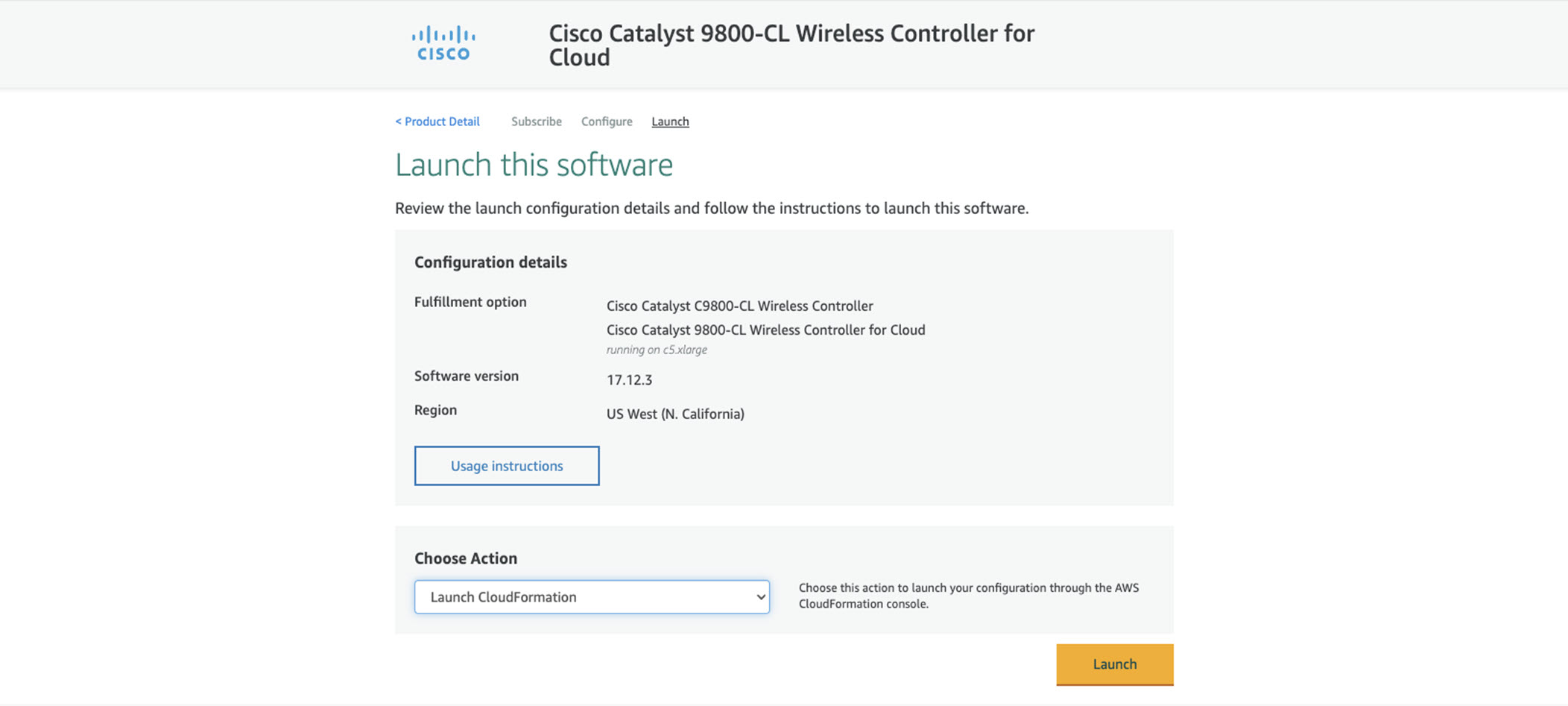 |
||
|
Step 7 |
You are redirected automatically to the CloudFormation service in the AWS console, and the template is selected.
Click Next.
|
||
|
Step 8 |
Enter the stack and instance details. The stack name is any name of your choice. Enter the C9800 hostname and choose the previously created key pair.
|
||
|
Step 9 |
Enter the network details. Choose the subnet and security group to assign to the wireless management interface. Make sure that the subnet and security group that you choose belong to the same selected VPC. Optionally, you can enter the IP address that will be assigned to the C9800 instance within the selected subnet. Make sure that the specific IP belongs to the subnet you selected and is not already in use. Otherwise, the stack creation will fail.
|
||
|
Step 10 |
Enter the username and password to remotely connect to the instance. This step is optional. If you don’t configure the username and password, you can log in via SSH using the default AWS user (ec2-user) and the instance key pair specified in the preceding step. Choose the instance type according to the scale. Cisco supports c5.xlarge (the default value), which corresponds to the supported scale of 1000 APs and 10,000 clients.  Click Next. |
||
|
Step 11 |
Leave the option page to the default and click Next. |
||
|
Step 12 |
Review the settings and click Create.
|
||
|
Step 13 |
Wait several seconds for the status to change from CREATE_IN_PROGRESS to CREATE_COMPLETE.  If the stack creation fails, the status shows ROLLBACK COMPLETE. Click the stack name to see the failure reason. In the following example, the IP address that was chosen was already assigned.  |
||
|
Step 14 |
Go to the EC2 dashboard and click Running Instances.  |
||
|
Step 15 |
The new instance is in Initializing state. Wait for several minutes until it changes to green.  Notice that the instance has the requested private IP and no public IP. At this point, the cloud instance of your Catalyst
9800 Wireless Controller is ready to use through a VPN connection.
 |
C9800-CL Configuration via CLI: Skip the Day-0 Guided Flow
If you want to skip the day-0 web-based guided flow and use the CLI to configure the basic settings, complete the following steps. After completing these steps, you can access the GUI for the day-1 configuration.
For C9800-CL on AWS cloud, GigabitEthernet 1 is the only available interface and has the following characteristics:
-
It is a Layer 3 interface (AWS only supports this type of interface)
-
It gets its IP address by using DHCP
There is no wireless CLI wizard for C9800-CL. The following steps are manual.
Procedure
|
Step 1 |
Access the CLI via SSH. Use the .pem file to authenticate with the certificate.
|
||
|
Step 2 |
Optionally, set the hostname: |
||
|
Step 3 |
Enter the config mode and add login credentials: |
||
|
Step 4 |
Verify the GigabitEthernet 1 configuration and IP address. The interface is configured for DHCP. |
||
|
Step 5 |
Disable the wireless network to configure the country code. |
||
|
Step 6 |
Configure the AP country domain. This configuration triggers the GUI to skip the day-0 flow, because the C9800 requires a country code to be operational. |
||
|
Step 7 |
A certificate is required for the AP to join the virtual C9800. This can be created automatically via the day-0 flow or manually by entering the following commands.
To access the main dashboard, go to https://<IP of the wireless management interface>. Use the credentials you entered earlier. Because the device has a country code configured, the GUI skips the day-0 page. You will get access to the main dashboard for day-1 configuration. |
||
|
Step 8 |
To provision the Cisco Catalyst 9800-CL Wireless Controller from Catalyst Center, change the management interface from DHCP to static: For more information on discovering and provisioning the Cisco Catalyst 9800-CL Wireless Controller, see Validated Profile: Wireless Automation Deployment Using Cisco Catalyst Center. |
||
|
Step 9 |
Perform the SWIM upgrade using Catalyst Center on the Cisco Catalyst 9800-CL Wireless Controller. See "Update the Software Image for the Cisco Catalyst 9800-CL Wireless Controller" in Validated Profile: Wireless Automation Deployment Using Cisco Catalyst Center. |
Operate the Solution
High Availability
Cisco Catalyst Center on AWS high availability (HA) implementation is as follows:
-
Single-node Elastic Compute Cloud (EC2) HA within an Availability Zone (AZ) is enabled by default.
-
When a Catalyst Center EC2 instance crashes, AWS automatically brings up another instance with the same IP address. This ensures uninterrupted connectivity and minimizes disruptions during critical network operations.
-
The experience and Recovery Time Objective (RTO) are similar to a power outage sequence in a bare-metal Catalyst Center appliance.
About Backup and Restore
Use the backup and restore functions in Catalyst Center VA to create backup files. You can restore the backup files to the same appliance (in case your Catalyst Center becomes unusable) or use them to migrate your Catalyst Center to a different appliance, for example:
-
Back up data from a Catalyst Center hardware appliance and restore the data to a Catalyst Center VA.
-
Back up data from one Catalyst Center VA and restore the data to another Catalyst Center VA.
 Important |
NetFlow data is not backed up when you back up Catalyst Center's automation and Assurance data. |
Backup and Restore—VA to VA
This procedure provides a high-level overview of how you can back up the data from one (source) Catalyst Center VA and restore it to another (target) Catalyst Center VA. For detailed instructions, see the "Backup and Restore" chapter in the Cisco Catalyst Center Administrator Guide.
Before you begin
-
Make sure that you successfully deployed two Catalyst Center VAs with Cisco Global Launchpad, AWS CloudFormation, or AWS Marketplace.
-
Make sure that both Catalyst Center VAs are up and running.
-
Make sure that the backup server is connected to the source Catalyst Center VA through a VPN.
-
Make sure that the backup server is reachable from the target Catalyst Center VA.
-
If you're using a Cloud backup (NFS) server, you'll need to know the backup password in order to log into the server.
Your backup server password is dynamically created. The password is composed of the first four characters of the VA pod name and the backup server's IP address without the periods. For example, if the VA pod name is DNAC-SJC and the backup server's IP address is 10.0.0.1, the backup server password is DNAC10001.

Note
You can find the VA pod name on the Dashboard pane after you choose the region that it's deployed in.
You can find the backup server's IP address in the View Catalyst Center pane.
Procedure
|
Step 1 |
Back up the data from the source Catalyst Center VA to a backup server. |
||
|
Step 2 |
Bring up the target Catalyst Center VA that you want to restore the data to. |
||
|
Step 3 |
Connect the target Catalyst Center VA to the backup server. (See Step 1.) |
||
|
Step 4 |
Configure the backup server on the target Catalyst Center VA. |
||
|
Step 5 |
Restore the data to the target Catalyst Center VA. |
||
|
Step 6 |
Reestablish connectivity with Cisco ISE. For more information, see "Configure Authentication and Policy Servers" in the Cisco Catalyst Center Administrator Guide.
|
||
|
Step 7 |
If self-signed certificates were in place on your network's devices, reprovision them in order to update their Catalyst Center certificates. For more information, see "Update Device Configuration Using Telemetry" in the Cisco Catalyst Center User Guide.
|
Backup and Restore—Hardware Appliance to VA
This procedure provides a high-level overview of how you can back up the data from a Catalyst Center hardware appliance and restore it to a Catalyst Center VA. For detailed instructions, see the "Backup and Restore" chapter in the Cisco Catalyst Center Administrator Guide.
Before you begin
-
Make sure that the hardware appliance used for the backup is a 44-core Catalyst Center appliance.
-
If you're using a Cloud backup (NFS) server, you'll need to know the backup password in order to log into the server.
Your backup server password is dynamically created. The password is composed of the first four characters of the VA pod name and the backup server's IP address without the periods. For example, if the VA pod name is DNAC-SJC and the backup server's IP address is 10.0.0.1, the backup server password is DNAC10001.

Note
You can find the VA pod name on the Dashboard pane after you choose the region that it's deployed in.
You can find the backup server's IP address in the View Catalyst Center pane.
Procedure
|
Step 1 |
Back up the data from the Catalyst Center hardware appliance. Make sure that the backup server is connected to Catalyst Center through a VPN. |
||
|
Step 2 |
Create a Catalyst Center VA. Make sure the Catalyst Center VA is up and running. |
||
|
Step 3 |
Connect the Catalyst Center VA to the backup server from Step 1. Make sure that the backup server is reachable from the Catalyst Center VA. |
||
|
Step 4 |
Configure the backup server on the Catalyst Center VA. |
||
|
Step 5 |
Restore the data on to the Catalyst Center VA. |
||
|
Step 6 |
Reestablish connectivity with Cisco ISE. For more information, see "Configure Authentication and Policy Servers" in the Cisco Catalyst Center Administrator Guide.
|
||
|
Step 7 |
If self-signed certificates were in place on your network's devices, reprovision them in order to update their Catalyst Center certificates. For more information, see "Update Device Configuration Using Telemetry" in the Cisco Catalyst Center User Guide.
|
Manage Catalyst Center VA Operations in Launchpad (Automated Mode)
Edit a VA Pod
You can edit only those VA pods that were created with connectivity. For those VA pods that were defined with another connectivity type, the Edit VA pod option is disabled in the dropdown list.
Procedure
|
Step 1 |
On the Dashboard pane, locate the VA pod that you want to edit. |
|
Step 2 |
In the bottom-right corner of the VA pod card, click the ellipsis icon (...) and choose Edit VA Pod. |
|
Step 3 |
In the Modify VPN Details page, make the relevant edits and click Next. |
|
Step 4 |
Review the edited details, and when you're ready, click Proceed to On-Prem Configuration. |
|
Step 5 |
Configure the on-premises connectivity. |
|
Step 6 |
Check the status of your network configuration. While your network administrator is configuring the tunnel, the tunnel configuration status displays as not configured with a padlock icon. After your network administrator completes the tunnel configuration and the tunnel is successfully established, the configuration status displays green with a success icon. |
|
Step 7 |
(Optional) To return to the Dashboard pane, click Go to Dashboard. |
Delete a VA Pod
You can delete a VA pod using Cisco Global Launchpad.
 Note |
|
Procedure
|
Step 1 |
On the Dashboard pane, locate the VA pod. |
||
|
Step 2 |
In the bottom-right corner of the VA pod card, click the ellipsis icon (...) and choose Delete VA Pod.
|
||
|
Step 3 |
In the Confirmation dialog box, in the text field, type DELETE. |
||
|
Step 4 |
Click Delete to confirm that the deletion of the VA pod. Deleting a VA pod takes approximately 20 to 40 minutes. |
View Catalyst Center VA Details
You can view Catalyst Center VA details in Cisco Global Launchpad.
Procedure
|
Step 1 |
On the Dashboard pane, locate the VA pod containing the Catalyst Center VA you want to view, and in the VA pod card, click Create/Manage Catalyst Center(s). |
|
Step 2 |
In the bottom-right corner of the Catalyst Center VA card, click the ellipsis icon (...) and choose View Details. |
|
Step 3 |
In the View Catalyst Center pane, view information, such as the Catalyst Center domain FQDN and network proxy. To the right of the View Catalyst Center pane, VA pod details are displayed. 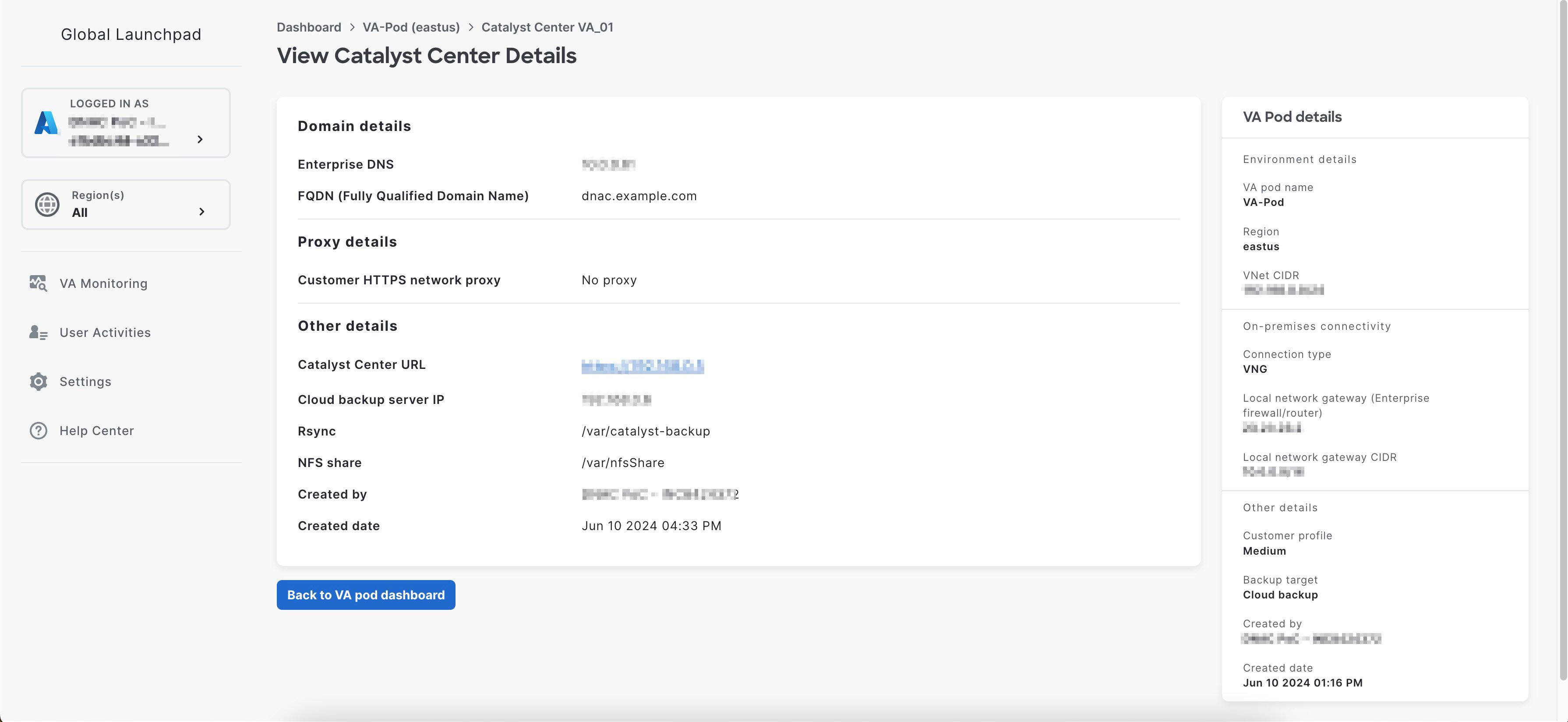 |
|
Step 4 |
(Optional) To exit this window, click Back to Catalyst Center(s). |
Delete an Existing Catalyst Center VA
You can delete an existing Catalyst Center VA from Cisco Global Launchpad.
Procedure
|
Step 1 |
On the Dashboard pane, locate the VA pod containing the Catalyst Center VA you want to delete, and in the VA pod card, click Create/Manage Cisco Catalyst Center(s). |
|
Step 2 |
In the bottom-right corner of the Catalyst Center VA card, click the ellipsis icon (...) and choose Delete Catalyst Center. |
|
Step 3 |
In the Confirmation dialog box, in the text field, type DELETE. |
|
Step 4 |
Click Delete to confirm that the deletion of the Catalyst Center VA. |
Troubleshoot the Deployment for Cisco Global Launchpad
Cisco Global Launchpad is designed to help you seamlessly configure Catalyst Center on AWS with minimal intervention. This section shows you how to troubleshoot common issues during the deployment of Catalyst Center on AWS.
 Note |
We recommend against making manual changes with Cisco Global Launchpad through the AWS console, because it can lead to issues that Cisco Global Launchpad cannot resolve. |
If you have any issues that are not addressed in this section, contact Cisco TAC.
Troubleshoot Docker Errors
If the error "port is already in use" displays while running the Docker images for Cisco Global Launchpad, you can troubleshoot it with the following possible solutions:
| Error |
Possible Solution |
||||
|---|---|---|---|---|---|
|
If you receive the following error while running the server application:
|
On Docker, run the server application:
While running the server application, run the client application:
|
||||
|
If you receive the following error while running the client application:
|
On Docker, run the client application:
|
Troubleshoot Login Errors
When you log in to Cisco Global Launchpad, you may encounter a login error. You can troubleshoot common login errors with the following possible solutions:
| Error | Possible Solution |
|---|---|
|
Invalid credentials. |
Re-enter your credentials and check that they're entered correctly. |
|
You don't have enough access. |
For admin users, verify that your account has administrator access permission. For subusers, verify that your administrator added you to the CiscoDNACenter user group. |
|
An operation to delete is in progress, please try again after some time. |
If an admin user deletes the |
Troubleshoot a Hosted Cisco Global Launchpad Error
On hosted Cisco Global Launchpad, when you trigger a root cause analysis (RCA) from the Trigger RCA pane, the Rate exceeded error can occur.
| Error | Possible Solution |
|---|---|
|
Rate exceeded. |
This error displays when a region receives the maximum number of API requests (10,000 per second). To resolve this issue, increase the limit in AWS with the Service Quotas service, or retry the operation after a few seconds. |
Troubleshoot Region Issues
You can troubleshoot region issues with the following possible solutions:
| Issue | Possible Solution | ||
|---|---|---|---|
|
While creating a new VA pod in a new region, Cisco Global Launchpad displays an error message or the screen freezes for more than 5 minutes and does not display a configuration-in-progress message. |
Make sure that any manual process on the AWS console has completed successfully, and try this step again. If the problem persists, contact Cisco TAC.
|
||
|
Your region setup fails and Cisco Global Launchpad displays a Bucket [name] did not stabilize error similar to the following:
|
Open a case with AWS and ask that they delete the failed resources from the back end. |
Troubleshoot VA Pod Configuration Errors
You can troubleshoot VA pod configuration errors with the following possible solutions:
| Error | Possible Solution | ||
|---|---|---|---|
|
+ Create VA Pod button disabled |
Hover your cursor over the disabled button to learn more about why it's disabled. The following are likely reasons why you can't create a new VA pod:
|
||
|
AMI ID for this region is not available for your account. |
When you click + Create a new VA pod, Cisco Global Launchpad validates the AMI ID for your selected region. If you encounter this error, the validation failed and you can't create a new pod in this region. Contact Cisco TAC to help you resolve the issue. |
||
|
Your VPN configuration is invalid. At this step you cannot update it so please delete the instance and create a new one. |
When configuring a VA pod, the following VPN vendors are not supported:
If you are using an unsupported VPN vendor, the following error message is displayed on the Configure the on-premises tunnel endpoint window: |
||
|
CustomerGateway with type "ipsec.1", ip-address "xx.xx.xx.xx", and bgp-asn "65000" already exists (RequestToken: f78ad45d-b4f8-d02b-9040-f29e5f5f86cf, HandlerErrorCode: AlreadyExists) |
You may encounter this error if you try to create more than one VA pod at a time. To resolve this error, delete the failed VA pod and recreate it. Ensure that you create only one VA pod at a time. |
||
|
AWS infrastructure failed. |
If the AWS configuration fails, return to the Dashboard pane and create a new VA pod.
|
||
|
AWS configuration fails when editing a VA Pod |
Make sure that any manual process on the AWS console completed successfully, and try this step again. If the problem persists, contact Cisco TAC.
|
||
|
Deleting VA Pod has failed |
Make sure that any manual process on the AWS console completed successfully, and try this step again. If the problem persists, contact Cisco TAC.
|
||
|
The resource you are trying to delete has been modified recently. Please refresh the page to get the latest changes and try again. |
If you encounter this error while deleting a VA pod, contact Cisco TAC. |
Troubleshoot a Network Connectivity Error
While creating a VA pod, if the IPsec tunnel or TGW connection isn't established, make sure that the tunnel is up on your on-premises firewall or router.
If the tunnel from the VA pod to TWG is green and the tunnel from the TWG to CGW is gray, make sure that:

-
You forwarded the correct configuration file to your network administrator.
-
Your network administrator made the necessary changes to the configuration file.
-
Your network administrator finished applying this configuration to your Enterprise firewall or router.
Troubleshoot Catalyst Center VA Configuration Errors
You can troubleshoot errors that occur while configuring a Catalyst Center VA with the following possible solutions:
| Error | Possible Solution |
|---|---|
|
Environment Setup failed |
|
|
Delete Failed |
If the Catalyst Center VA deletion fails, contact Cisco TAC. |
Update the DNS Server on a Catalyst Center VA Using the AWS Console
To update the DNS server IP address configured on a Catalyst Center VA, use the consent token you obtained from Cisco TAC and follow the steps in this procedure.
Before you begin
Contact Cisco TAC to get a consent token to be able to get full shell access.
Procedure
|
Step 1 |
Log in to the AWS console. |
|
Step 2 |
Choose . |
|
Step 3 |
Choose the instance ID that you want to change and click Connect. The Connect to instance page is displayed with the EC2 Instance Connect tab selected by default. 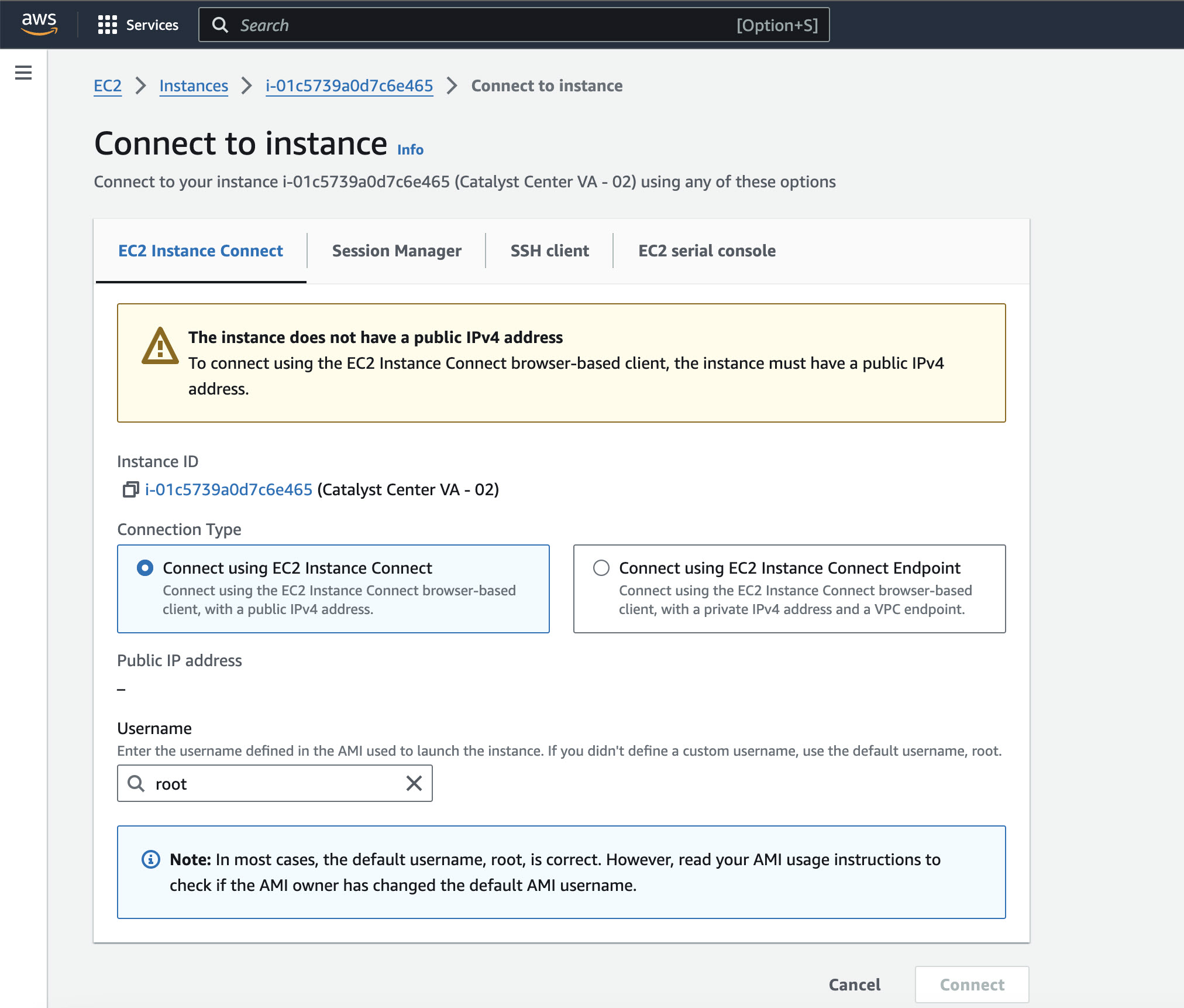 |
|
Step 4 |
Click the EC2 serial console tab. The Catalyst Center VA instance ID and serial port are displayed. 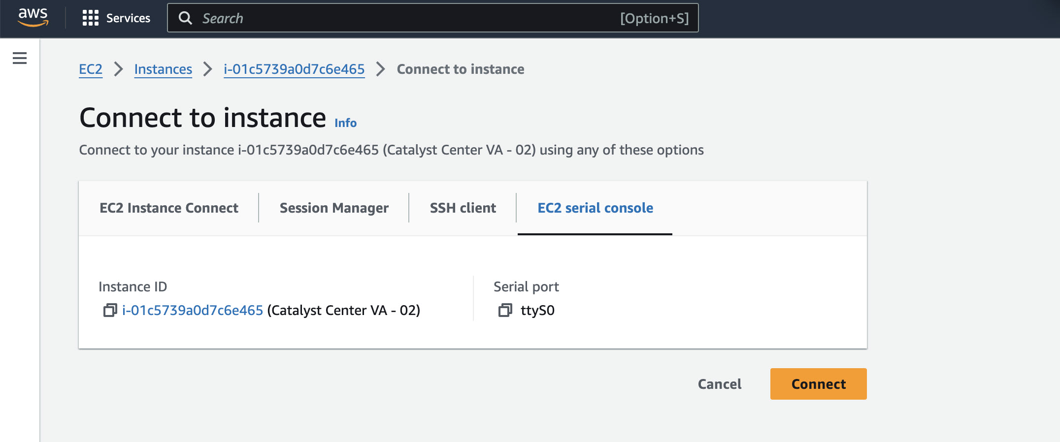 |
|
Step 5 |
Click Connect. The Maglev console is displayed. 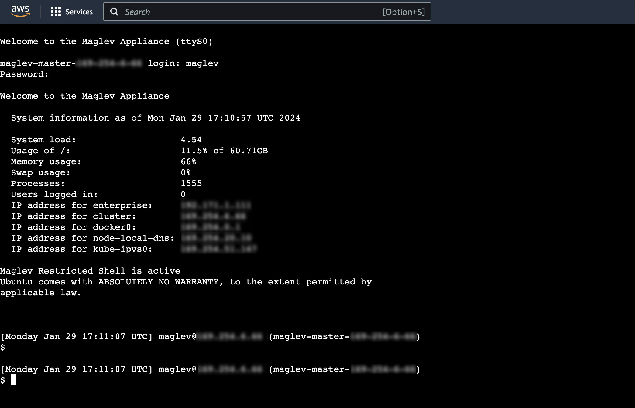 |
|
Step 6 |
At the Login prompt, enter maglev as the username. |
|
Step 7 |
At the Password prompt, enter the password that was configured during the initial deployment, regardless of whether you deployed your Catalyst Center VA using Cisco Global Launchpad, AWS CloudFormation, or AWS Marketplace. |
|
Step 8 |
Gain full shell access by using the consent token that you obtained from Cisco TAC: For example: |
|
Step 9 |
Set the terminal to display in color: |
|
Step 10 |
Run the sudo maglev-config update command. The Configuration wizard presents an abbreviated version of the same series of screens shown in, for example, Configure a Secondary Node Using the Maglev Wizard in the Cisco Catalyst Center Appliance Installation Guide. When the DNS server IP address setting is displayed, change the DNS server IP address to the preferred one. After you finish making changes on each screen, choose next>>, as needed, to proceed through the Configuration wizard. |
|
Step 11 |
At the end of the configuration process, a message appears, stating that the Configuration wizard is now ready to apply your changes. The following options are available:
|
|
Step 12 |
To complete the change, choose proceed>>. The Configuration wizard applies the changes you made. At the end of the configuration process, a CONFIGURATION SUCCEEDED! message appears. |
Troubleshoot Concurrency Errors
You troubleshoot the concurrency errors with the following possible solutions:
| Error | Possible Solution |
|---|---|
|
Unable to delete a Pod or a Catalyst Center created by another user. |
You cannot delete a component, such as a VA pod or Catalyst Center VA, that another user created while a different action is in progress on the component. After the action completes, you or any other user can delete the component. For example, you cannot delete a VA pod or Catalyst Center VA while it is in any of the following processes or states:
|
|
The status of a Pod has been changed recently. |
If you tried to delete a VA pod, the original user account that created the VA pod may have performed a concurrent action. This concurrency issue changes the status of the selected VA pod. To view the updated status of the VA pod, click Refresh. |
Troubleshoot Other Deployment Issues
You can troubleshoot other issues that occur while deploying a Catalyst Center VA on AWS with the following possible solutions:
| Issue | Possible Reasons and Solutions |
|---|---|
|
Resources are green, but the Proceed button is disabled. |
On some steps, you can only proceed if all the resources have been set up successfully. To ensure the integrity of the deployment, the Proceed button remains disabled until the setup is complete and all the resources have been configured and loaded. Sometimes, the screen shows that the resources have been successfully set up, but the Proceed button is still disabled. In this case, you need to wait a few more seconds for some resources to load. After all the resources have been configured and loaded, the Proceed button is enabled. |
|
Failure when deploying multiple VA pods with the same CGW in single region. |
Make sure that:
|
|
Unable to SSH or ping the Catalyst Center VA. |
You cannot connect via SSH or ping the Catalyst Center VA, although the tunnel is up and the application status is complete (green). This issue might occur if the on-premises CGW is configured incorrectly. Verify the CGW configuration and try again. |
|
Session ended |
If your session times out while operations are in progress, such as triggering an RCA, the operations may abruptly end and display a Session ended notification. If your session times out, click Ok, log back in, and restart the operations. |
Password Recovery and Reset on AWS
The following tasks guide you through the tasks that help your reset your Cisco ISE virtual machine password. Choose the tasks that you need and carry out the steps detailed.
Change the Cisco ISE GUI Password via the Serial Console
Procedure
|
Step 1 |
Log in to your AWS account and go to the EC2 dashboard. |
|
Step 2 |
From the left-side menu, click Instances. |
|
Step 3 |
Click the instance ID for which you want to change the password. If you know the password, skip to Step 5 of this task. |
|
Step 4 |
To log in to the serial console, you must use the original password that was set at the installation of the instance. To view the configured password, complete the following steps: |
|
Step 5 |
Click Connect. The EC2 serial console tab is displayed. |
|
Step 6 |
Click Connect. |
|
Step 7 |
A new browser tab is displayed. If the screen is black, press Enter to view the login prompt. |
|
Step 8 |
Log in to the serial console. If the password that was displayed in Step 4 does not work, see the Password Recovery section. |
|
Step 9 |
Use the application reset-passwd ise iseadmin command to set a new web UI password for the iseadmin account. |
Create New Public Key Pair
Procedure
|
Step 1 |
Create a new public key in AWS. For instructions on how to create public key pairs, see Create key pairs. |
|
Step 2 |
Log in to the AWS serial console as detailed in the preceding task. |
|
Step 3 |
To create a new repository to save the public key to, see Creating a private repository. If you already have a repository that is accessible through the CLI, skip to the next step. |
|
Step 4 |
To import the new public key, use the command crypto key import <public key filename> repository <repository name> |
|
Step 5 |
When the import is complete, you can log in to Cisco ISE via SSH using the new public key. |
Password Recovery
There is no mechanism for password recovery for Cisco ISE on AWS. You may need to create new Cisco ISE instances and perform backup and restore of configuration data.
Editing the user data for an EC2 instance in AWS does not change the CLI password that is used to log in to the serial console, as the setup script is not run. The Cisco ISE virtual instance is not affected.
Trigger a Root Cause Analysis
On Cisco Global Launchpad, you can trigger a root cause analysis (RCA) to help you identify the root cause of cloud infrastructure or Catalyst Center VA deployment issues. The RCA operation collects logs from the cloud provider and stores them in your cloud storage. The RCA bundle includes logs about backups, backend operations, resources, alarms, and events.
Procedure
|
Step 1 |
On the Dashboard pane, locate the VA pod containing the Catalyst Center VA that you want to trigger an RCA on, and in the VA pod card, click Create/Manage Cisco Catalyst Center(s). |
||
|
Step 2 |
In the bottom-right corner of the Catalyst Center VA card, click the ellipsis icon (...) and choose Trigger RCA. |
||
|
Step 3 |
In the Trigger RCA window, in the RCA Logs area, click Trigger RCA to gather and bundle the logs.
This process takes a few minutes. After the process completes, the URL to the bundle, where the logs are located, is displayed. |
||
|
Step 4 |
Under Destination, click the URL that is displayed. The Azure console opens in a new browser window. After you log in, locate the destination link within the container and click it. |
AWS Config and Audit Log Details
AWS Config is an AWS tool that continually assesses, monitors, and evaluates resource configurations to aid in operational troubleshooting by correlating configuration changes to specified events and states. Cisco Global Launchpad uses AWS Config to audit the configuration. When AWS Config detects a change in the configuration, Cisco Global Launchpad generates an email notifying you that configuration changes have taken place.
View Amazon CloudWatch Alarms
Cisco Global Launchpad uses Amazon CloudWatch alarms to monitor resource usage and check for unusual behavior. The AWS RCA feature also uses Amazon CloudWatch alarms.
If a threshold is met, alerts are sent to the email ID that you configured during your first log in to Cisco Global Launchpad or to the email ID in the user settings, if it was updated.
 Note |
|
Before you begin
Make sure you successfully configured your AWS account.
Procedure
|
Step 1 |
Log in to the AWS console. The AWS console is displayed. The Alerts area displays critical alerts from AWS CloudWatch. This area shows the name of the alarm that generated each alert, and shows the region name, metric name, and namespace for each alarm. |
|
Step 2 |
In the Alerts area
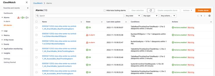 |
|
Step 3 |
On the Alarms page, enter the environment name used to deploy Catalyst Center in the Search field. Alarms pertaining to the Catalyst Center instance with the specified environment name are displayed. |
|
Step 4 |
Click the name of an alarm. Details about the alarm are displayed in the Details tab. To view other information, click the Actions, History, or Parent alarms tabs. 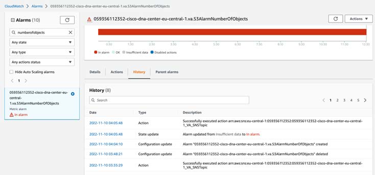 |
Hardware and Software Used for Validation
This solution was validated using the following hardware and software:
|
Component |
Version |
|---|---|
|
Catalyst Center |
2.3.7.7 |
|
Cisco ISE |
3.3 P3 |
|
Wireless Controller 9800-CL |
17.12.3 |
|
Catalyst Switches |
17.12.4 |
|
Access Points |
17.12.3 |
Glossary
|
Term |
Definition |
|---|---|
|
AZ |
availability zone |
|
Cisco ISE |
Cisco Identity Services Engine |
|
HA |
high availability |
|
VA |
virtual appliance |
|
VPC |
virtual private cloud |
Feedback and Discussion
For comments and suggestions about our guides, join the discussion on Cisco Community.
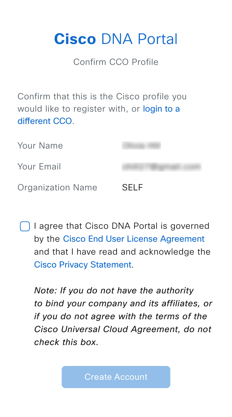
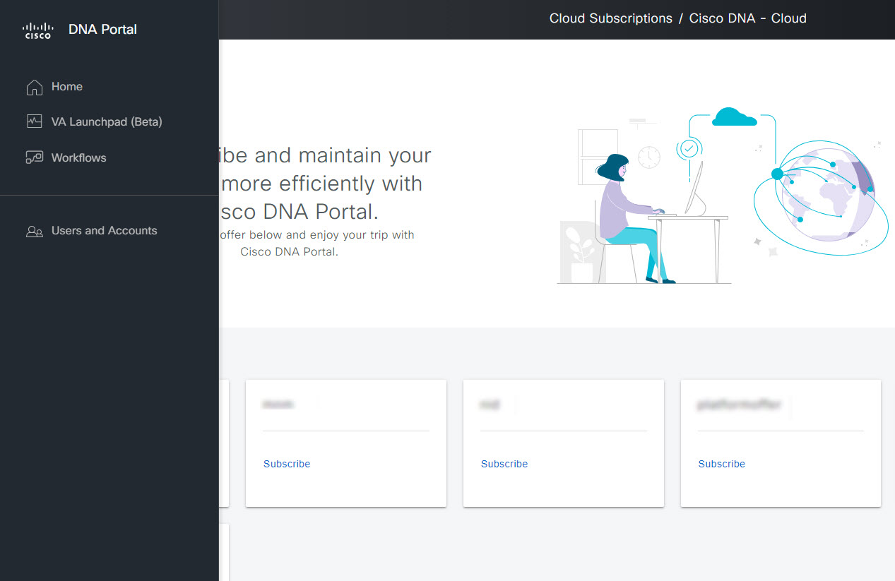
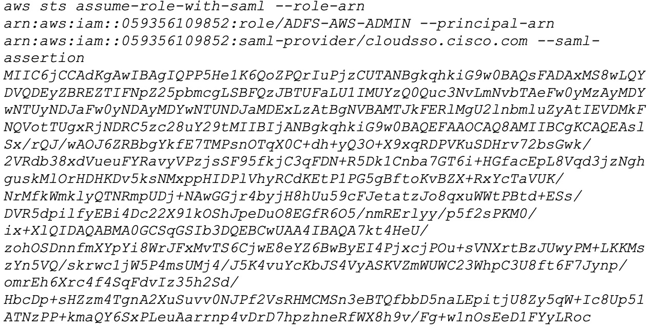
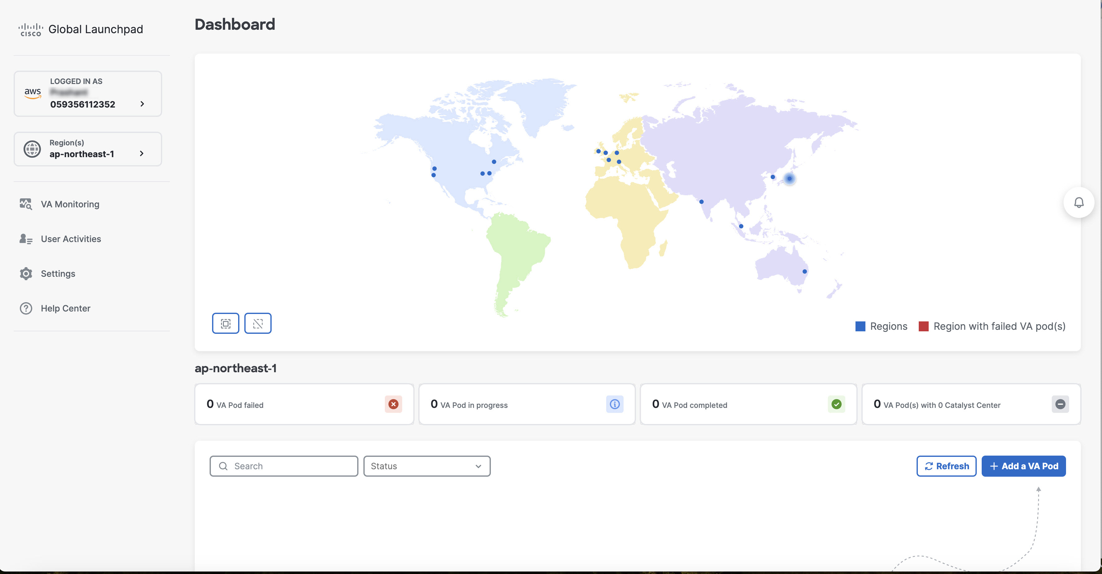
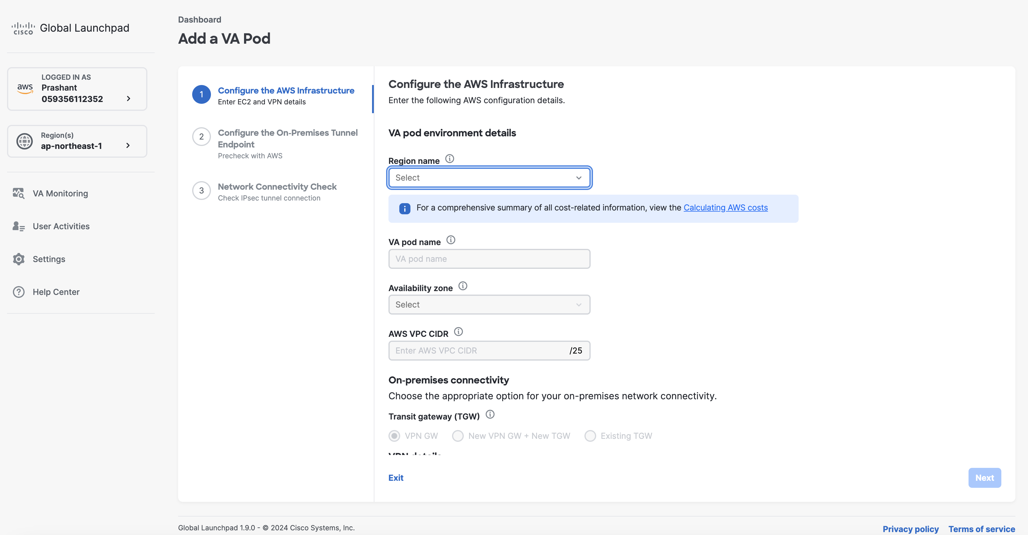
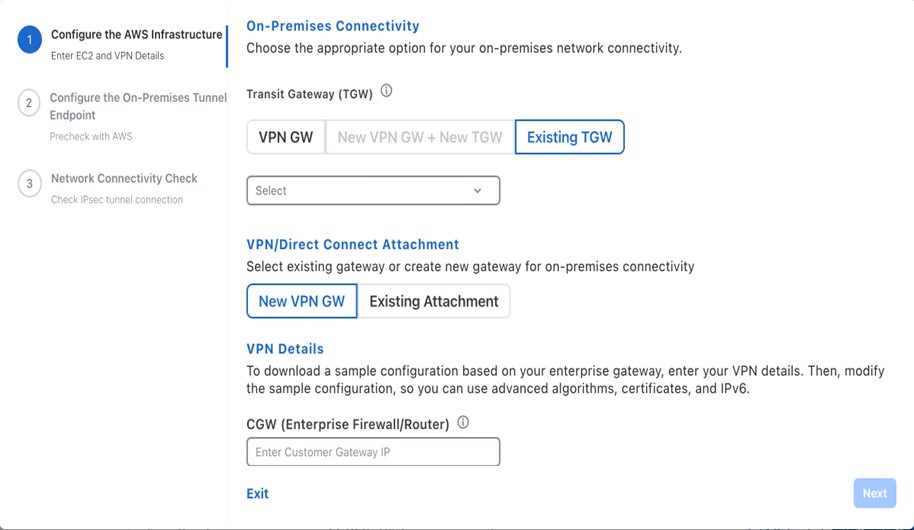
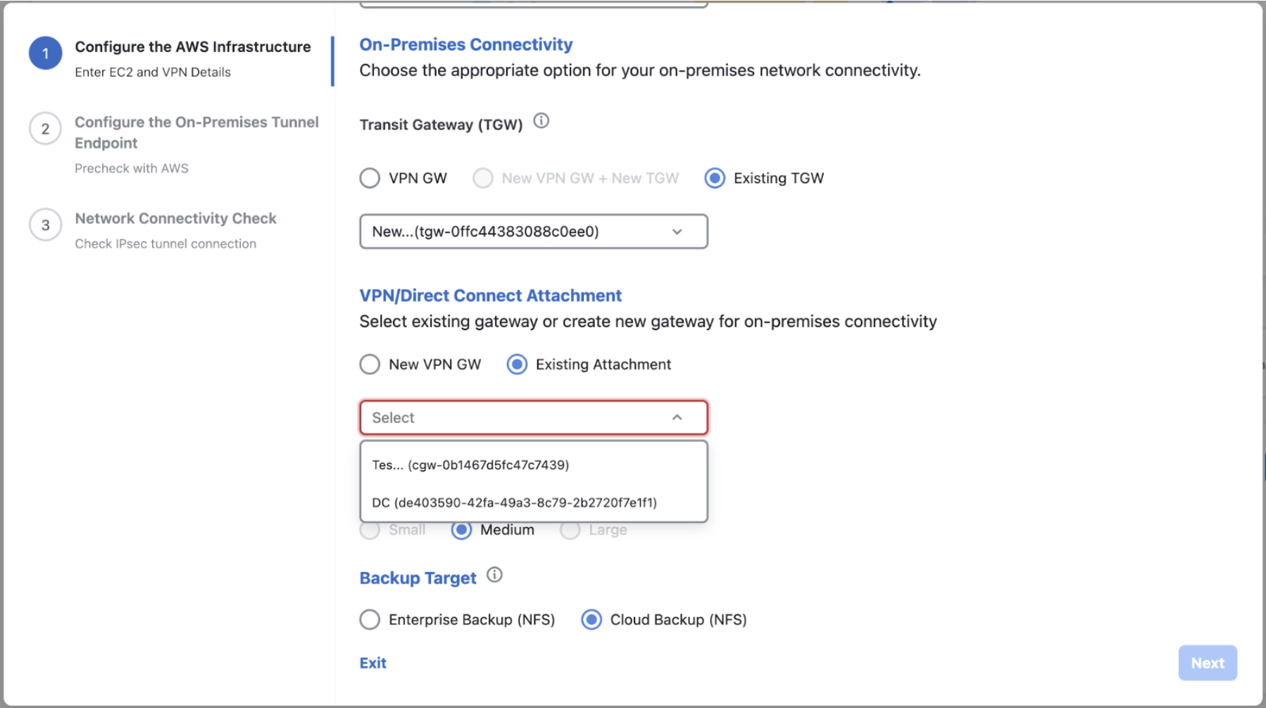
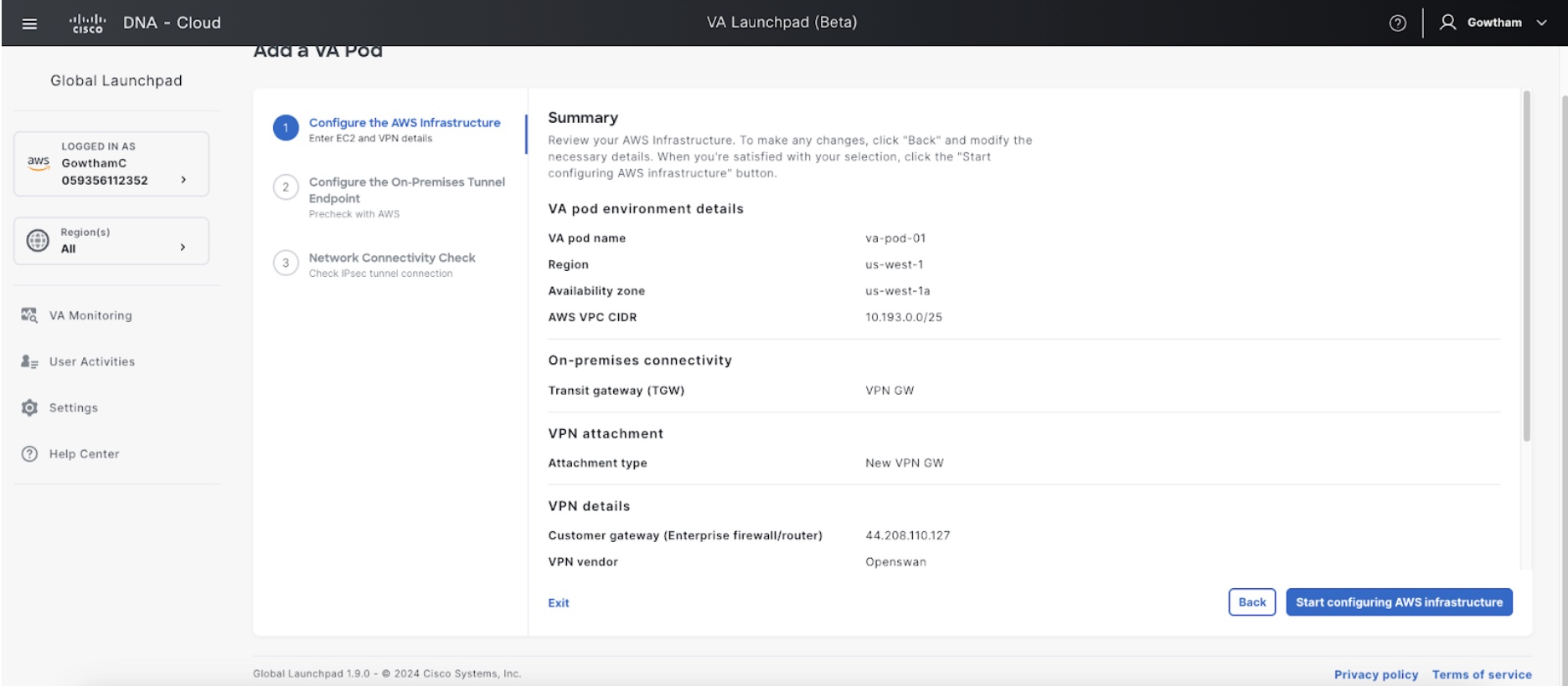
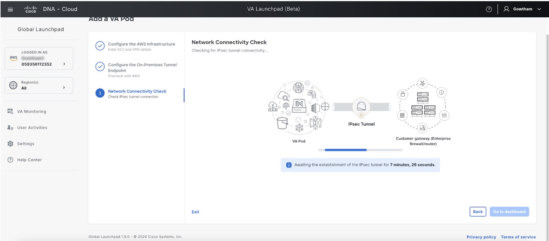
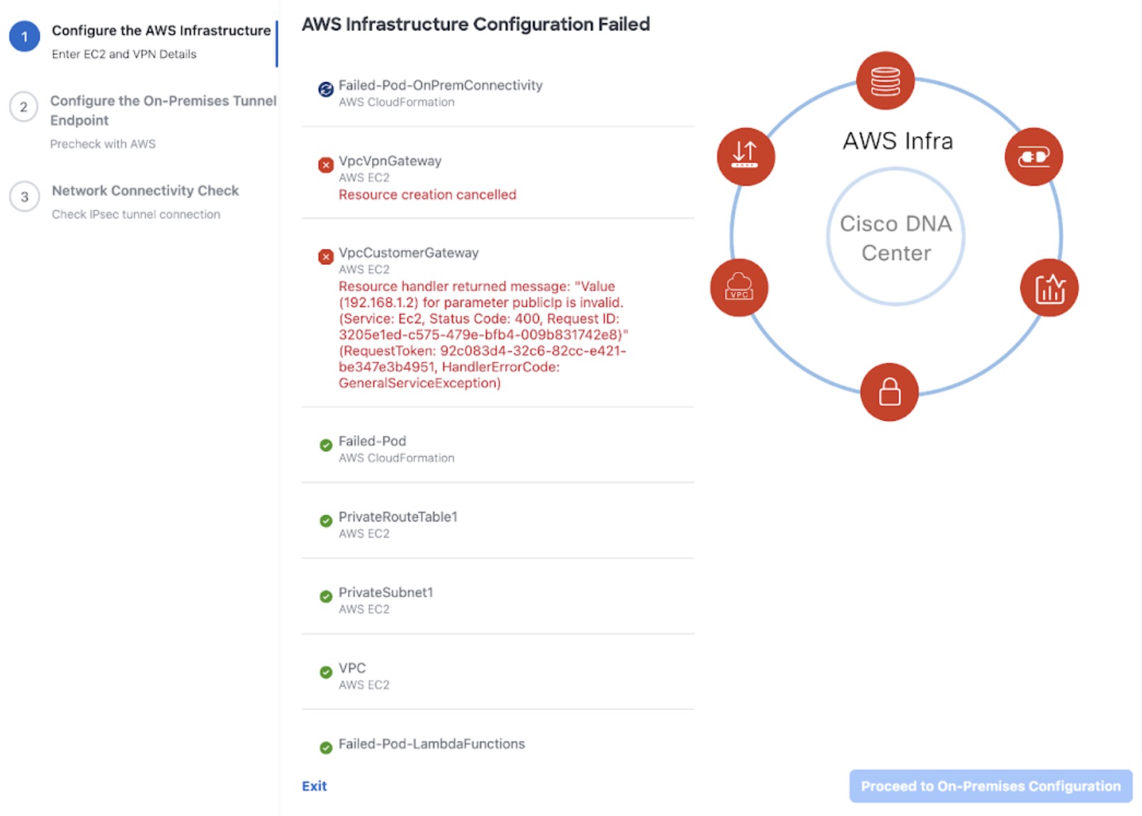
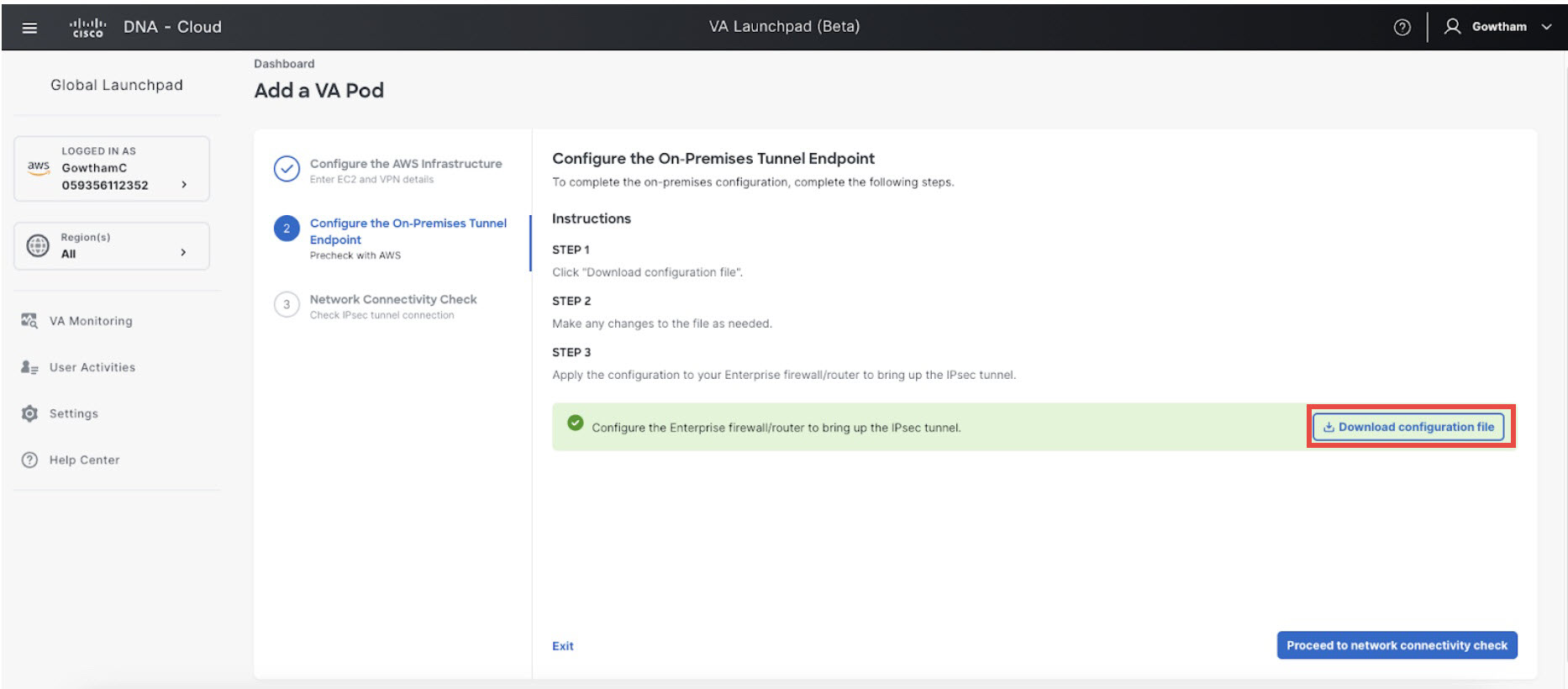
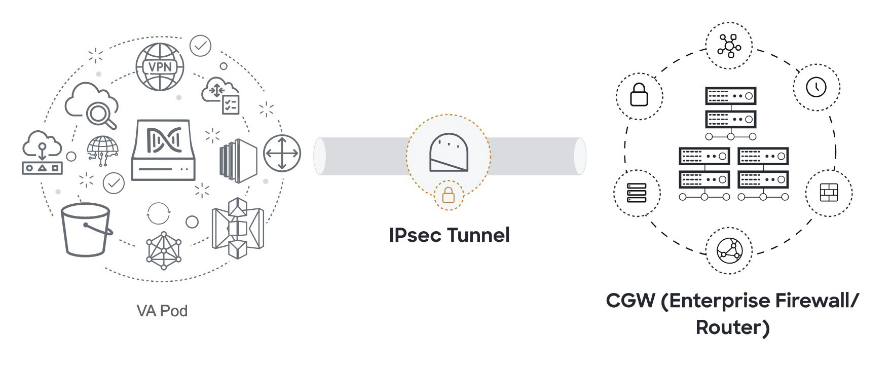
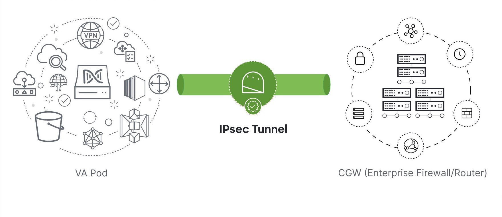

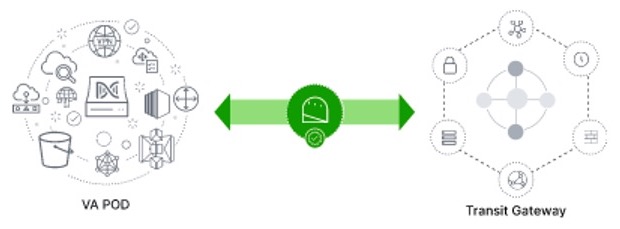
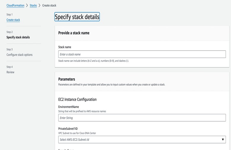
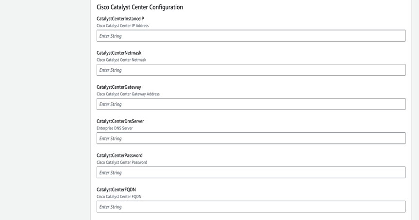

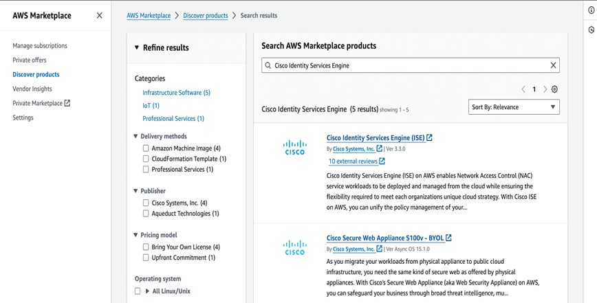
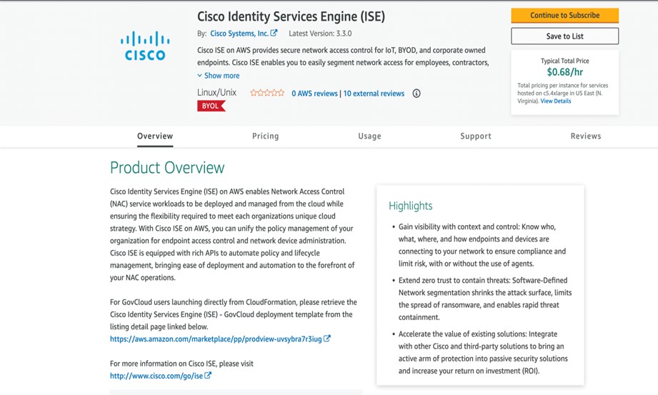
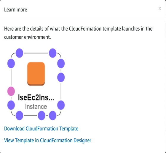
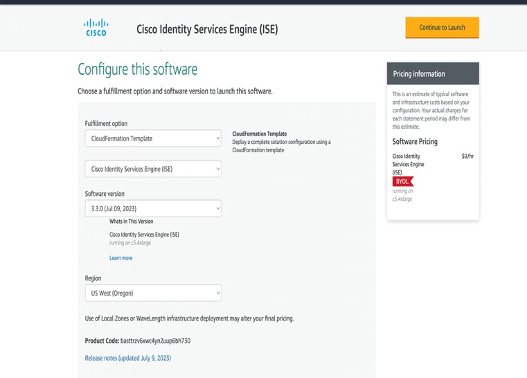
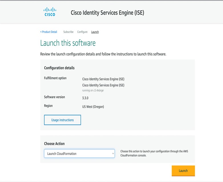


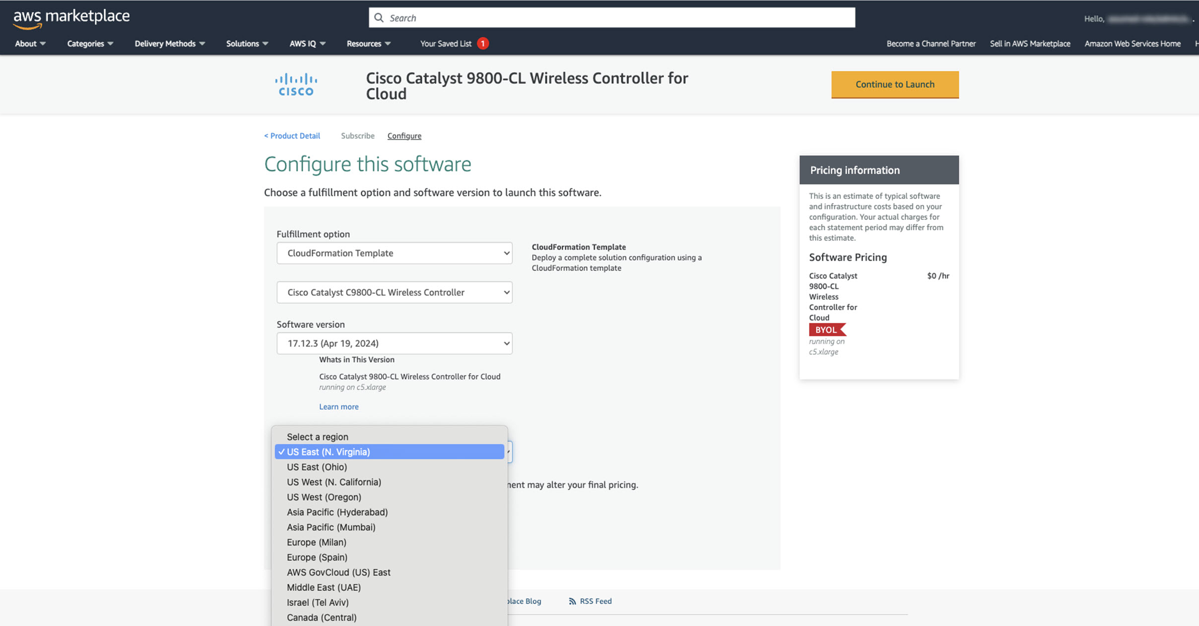


 Feedback