Introduction
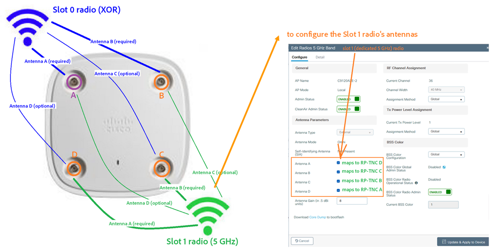
On the C9115AXE, C9120AXE and C9120AXP access points, the mapping of the radios' internal transceivers, to the labeled Reverse Polarity Threaded Neill-Concelman (RP-TNC) ports on the AP ("A", "B", "C", "D"), is different for the Slot 1 (dedicated 5 GHz) radio, than for the Slot 0 (XOR) radio. This article explains how the antenna mapping works, and describes the options for configuring RP-TNC antennas with these AP models.
Mapping to RP-TNC Ports
On the C9115AXE, C9120AXE and C9120AXP access points, the mapping of the radios' transceivers to the labeled RP-TNC ports on the AP ("A", "B", "C", "D") works like this:
- For the Slot 0 radio (interface Dot11Radio0, the XOR radio), what the software calls "Antenna A" maps to physical RP-TNC port "A", "Antenna B" maps to port "B", "Antenna C" to port "C", and "Antenna D" maps to port "D"
- However, for the Slot 1 radio (interface Dot11Radio1, the dedicated 5 GHz radio), what the software calls "Antenna A" maps to physical RP-TNC port "D", "Antenna B" maps to port "C", "Antenna C" to port "B", and "Antenna A" to port "D"

Configuration Restrictions
The following configuration restrictions apply to these APs' antennas:
- For each slot, the antennas that the software calls "A" and "B" must be enabled
- Thus, if the Slot 0 radio is in use, external antennas must be connected to (at least) physical ports "A" and "B"
- And, if the Slot 1 radio is in use, external antennas must be connected to (at least) physical ports "D" and "C"
- No antenna may be enabled for a radio, unless all antennas that precede it in alphabetic order are enabled. Thus, "antenna D" may not be enabled, unless antennas "C", "B" and "A" are enabled
Valid Configuration Options with RP-TNC Antennas
Thus, the C9115AXE, C9120AXE and C9120AXP access points support only the following external antenna configurations, if using only the RP-TNC ports (without the DART-4):
- If both Slot 0 and Slot 1 are enabled:
- Four external antennas connected to physical ports A, B, C and D, with all antennas oriented to the same coverage area
- Two external antennas aimed in one direction, connected to physical ports A and B - these will be used by the Slot 0 radio, and two external antennas aimed in a different direction, connected to physical ports C and D - used by the Slot 1 radio. In this configuration, the software should be configured to have only antennas "A" and "B" enabled (for both radios)
- If only Slot 0 is enabled
- At least two external antennas connected to physical ports A and B (optionally, with third [and fourth] antennas connected to C [and D]), oriented in the same direction
- The software should be configured with antennas "A" and "B" (optionally, "C" [and "D"]) enabled
- If only Slot 1 is enabled
- At least two external antennas connected to physical ports D and C (optionally, with third [and fourth] antennas connected to B [and A]), oriented in the same direction
- The software should be configured with antennas "A" and "B" (optionally, "C" [and "D"]) enabled.
If there is a requirement that both the Slot 0 and Slot 1 radios have four antennas connected, with the antennas oriented in different directions, then use a DART-4 connector. The antennas connected to the DART-4 will be used by Slot 0, while the four RP-TNC antennas will be used by Slot 1.

 Feedback