PPP Troubleshooting Flowchart
Available Languages
Contents
Introduction
This flowchart helps you to troubleshoot Point-to-Point Protocol (PPP), which is widely used for multiple Access technology solutions.
In the flowcharts and sample output shown below, we have set up an Integrated Services Digital Network (ISDN) basic rate interface (BRI) PPP connection to another using Legacy Dialer-on-Demand Routing (DDR). However, the same troubleshooting steps apply to connections to other routers (such as branch offices) with PPP connections when using Dialer Rotary-Group, Dialer Profile, or PPP over serial links.
For further information on Point-to-Point Protocol, and its supported features in Cisco IOS® software, refer to Cisco Learning Connection (registered customers only) and search using the keyword ppp in the Search for training field.
For a detailed explanation of the different phases of PPP negotiation and the output of debug ppp negotiation, refer to Configuring and Troubleshooting PPP Password Authentication Protocol (PAP).
Prerequisites
Requirements
Make sure you meet these prerequisites:
-
Enable debug ppp negotiation and debug ppp authentication.
-
You must read and understand the debug ppp negotiation output. Refer to Understanding debug ppp negotiation Output for more information.
-
The PPP authentication phase does not begin until the Link Control Protocol (LCP) phase is complete and is in "open" state. If debug ppp negotiation does not indicate that LCP is open, troubleshoot this issue before you proceed.
Components Used
This document is not restricted to specific software and hardware versions.
Terminology
Local machine (or local router): This is the system the debugging session is currently being run on. As you move the debug session from one router to the other, apply the term "local machine" to the other router.
Peer: The other end of the point-to-point link. Therefore, this device is not the local machine.
For example, if you run the debug ppp negotiation command on RouterA, this is the local machine, and RouterB is the peer. However, if you shift the debugging over to RouterB, then it becomes the local machine and RouterA becomes the peer.
Note: The terms local machine and peer do not imply a client-server relationship. Depending on where the debug session is run, the dialin client could be the local machine or peer.
Conventions
Refer to Cisco Technical Tips Conventions for more information on document conventions.
Troubleshooting Flowcharts
This document includes some flowcharts to assist in troubleshooting.
Note: In order to troubleshoot successfully, do not skip any of the steps shown in these flowcharts.
PPP Link Control Protocol (LCP) Phase
Asynchronous Modems used for PPP Connectivity
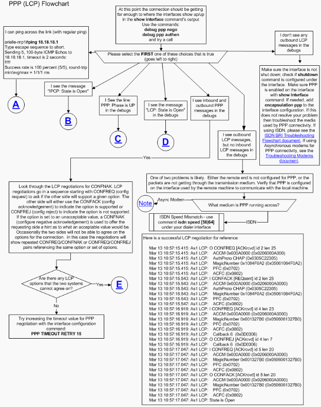
This section explains how Asynchronous Modems can be used for PPP connectivity. Outgoing LCP frames are seen on the local router, but there are no incoming LCP frames.
In this case, the problem could be due to one of two possibilities:
-
The modems of both the local router and the remote router train up, but PPP does not start on the remote router. To troubleshoot this problem, refer to the Modems do train up okay, but PPP does not start section in the Troubleshooting Modems document.
-
The modems of both the local and remote routers do train up okay, and PPP starts on both routers, but the call immediately drops. This destroys any chance of receiving incoming LCP frames from remote routers. To troubleshoot this problem, refer to the Modems do train up okay, PPP starts, but the call later drops section in the Troubleshooting Modems document.
For more detailed information on modem troubleshooting, refer to Troubleshooting Modems.
PPP Outgoing LCP Options
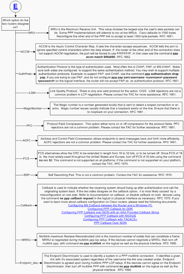
The flowchart below highlights several of the most common PPP LCP parameters that can be negotiated during the LCP phase. This flowchart helps you to locate which LCP parameters your PPP local machine is not negotiating with the PPP remote peer.
PPP Authentication Phase
Point-to-Point Protocol provides an optional phase which guarantees the network user a secured data transmission to enhance network security. On some links it may be desirable to require a PPP peer to authenticate itself before allowing network-layer protocol packets to be exchanged. For any PPP implementation, the authentication phase is optional by default. If a PPP network administrator wants the PPP peer to use a specific authentication protocol, he must request the use of that authentication protocol during the PPP LCP phase. That is, the authentication protocol used must be one of the negotiated PPP LCP options between both PPP peers.
At this stage, only PPP LCP, authentication protocol, and link quality monitoring packets are allowed during authentication phase. Ensure that there are no problems at this stage with any PPP LCP-negotiated parameters before following the troubleshooting steps in this section.
For detailed troubleshooting information for PPP authentication phase problems, refer to the Troubleshooting PPP (CHAP or PAP) Authentication flowchart.
PPP NCP Negotiations
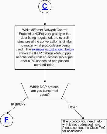
While different Network Control Protocols (NCPs) vary greatly in the data being negotiated, the overall structure of the conversation is similar no matter what protocols are being used. This section only covers IP (IPCP) NCP protocol negotiation.
The output below shows the debug output for a successful IP negotiation during PPP NCP negotiation:
As4 PPP: Phase is UP
 As4 IPCP: O CONFREQ [Not negotiated] id 1 len 10
 As4 IPCP:    Address 10.1.2.1 (0x03060A010201)
 As4 IPCP: I CONFREQ [REQsent] id 1 len 28
 As4 IPCP:    CompressType VJ 15 slots CompressSlotID (0x0206002D0F01)
 As4 IPCP:    Address 0.0.0.0 (0x030600000000)
 As4 IPCP:    PrimaryDNS 0.0.0.0 (0x810600000000)
 As4 IPCP:    SecondaryDNS 0.0.0.0 (0x830600000000)
 As4 IPCP: O CONFREJ [REQsent] id 1 len 10
 As4 IPCP:    CompressType VJ 15 slots CompressSlotID (0x0206002D0F01)
 As4 CCP: I CONFREQ [Not negotiated] id 1 len 15
 As4 CCP:    MS-PPC supported bits 0x00000001 (0x120600000001)
 As4 CCP:    Stacker history 1 check mode EXTENDED (0x1105000104)
 As4 LCP: O PROTREJ [Open] id 3 len 21 protocol CCP
 As4 LCP:  (0x80FD0101000F12060000000111050001)
 As4 LCP:  (0x04)
 As4 IPCP: I CONFACK [REQsent] id 1 len 10
 As4 IPCP:    Address 10.1.2.1 (0x03060A010201)
 %LINEPROTO-5-UPDOWN: Line protocol on Interface Async4, changed state to up
 As4 IPCP: I CONFREQ [ACKrcvd] id 2 len 22
 As4 IPCP:    Address 0.0.0.0 (0x030600000000)
 As4 IPCP:    PrimaryDNS 0.0.0.0 (0x810600000000)
 As4 IPCP:    SecondaryDNS 0.0.0.0 (0x830600000000)
 As4 IPCP: O CONFNAK [ACKrcvd] id 2 len 22
 As4 IPCP:    Address 10.1.2.2 (0x03060A010202)
 As4 IPCP:    PrimaryDNS 10.2.2.3 (0x81060A020203)
 As4 IPCP:    SecondaryDNS 10.2.3.1 (0x83060A020301)
 As4 IPCP: I CONFREQ [ACKrcvd] id 3 len 22
 As4 IPCP:    Address 10.1.2.2 (0x03060A010202)
 As4 IPCP:    PrimaryDNS 10.2.2.3 (0x81060A020203)
 As4 IPCP:    SecondaryDNS 10.2.3.1 (0x83060A020301)
 ip_get_pool: As4: validate address = 10.1.2.2
 ip_get_pool: As4: using pool default
 ip_get_pool: As4: returning address = 10.1.2.2
 set_ip_peer_addr: As4: address = 10.1.2.2 (3) is redundant
 As4 IPCP: O CONFACK [ACKrcvd] id 3 len 22
 As4 IPCP:    Address 10.1.2.2 (0x03060A010202)
 As4 IPCP:    PrimaryDNS 10.2.2.3 (0x81060A020203)
 As4 IPCP:    SecondaryDNS 10.2.3.1 (0x83060A020301)
 As4 IPCP: State is Open
 As4 IPCP: Install route to 10.1.2.2
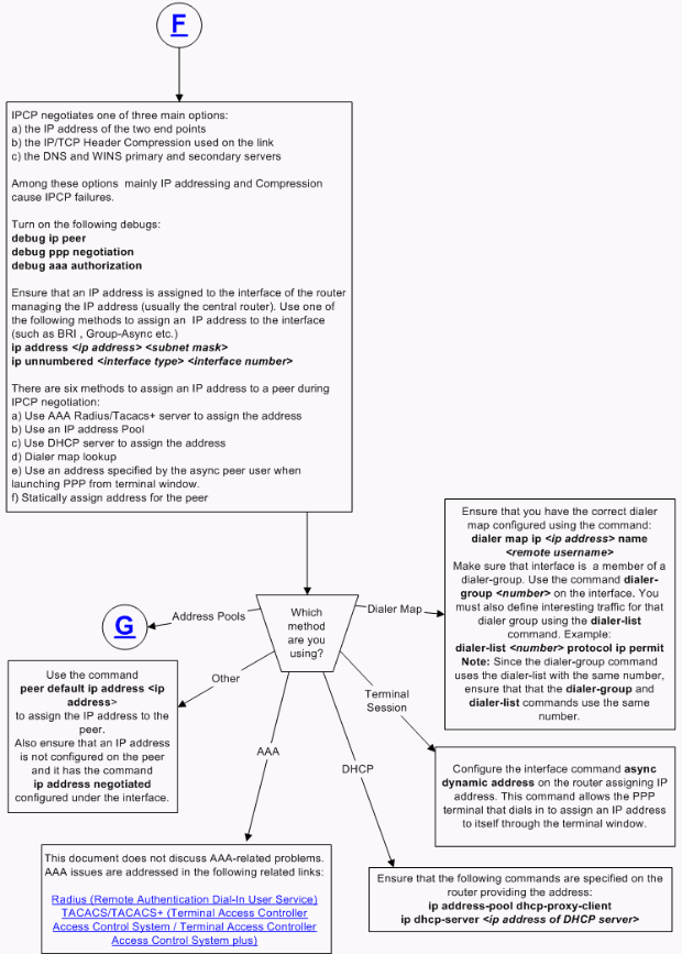
IPCP Does Not go Into Open State in NCP Negotiation Phase
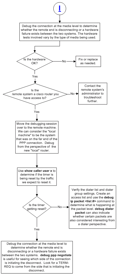
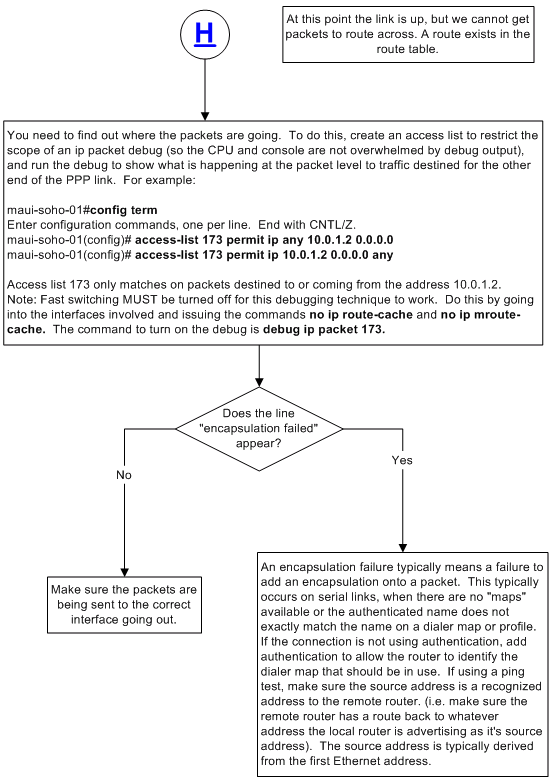
PPP Link Stability Problems
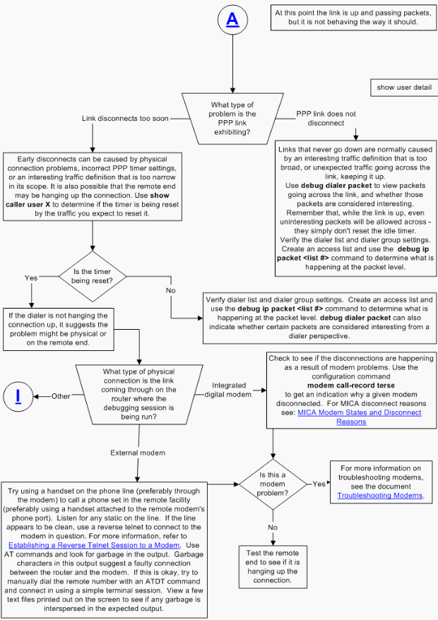
As stated in the flowchart below, at this point, the link is up and passing packets, but it is not behaving as it should.
Cannot Route Packets Over an IP PPP Link
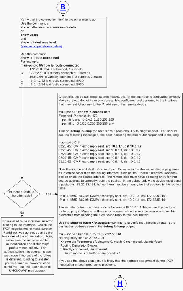
The output below shows the show caller user and show ip interface brief command output when a call is terminated successfully and IP packets can be sent to the remote peer over the PPP connection.
maui-soho-01#show caller user maui-soho-02 detail
   User: maui-soho-02, line BR0:1, service PPP
   Active time 00:02:21, Idle time 00:00:57
   Timeouts: Absolute Idle
   Limits: - 00:02:00
   Disconnect in: - 00:01:02
   PPP: LCP Open, CHAP (local <--> local), IPCP
   LCP: -> peer, AuthProto, MagicNumber
   <- peer, AuthProto, MagicNumber
   NCP: Open IPCP
   IPCP: <- peer, Address
   -> peer, Address
   Dialer: Connected to #, inbound
   Idle timer 120 secs, idle 57 secs
   Type is ISDN, group BRI0
   IP: Local 10.0.1.1/24, remote 10.0.1.2
   Counts: 123 packets input, 3246 bytes, 0 no buffer
   0 input errors, 0 CRC, 0 frame, 0 overrun
   119 packets output, 2940 bytes, 0 underruns
   0 output errors, 0 collisions, 0 interface resets
   maui-soho-01#show ip interface brief
   Interface IP-Address OK? Method Status Protocol
   BRI0 10.0.1.1 YES NVRAM up up
   BRI0:1 unassigned YES unset up up
   BRI0:2 unassigned YES unset down down
   Ethernet0 172.22.53.160 YES NVRAM up up
   Serial0 unassigned YES NVRAM administratively down down
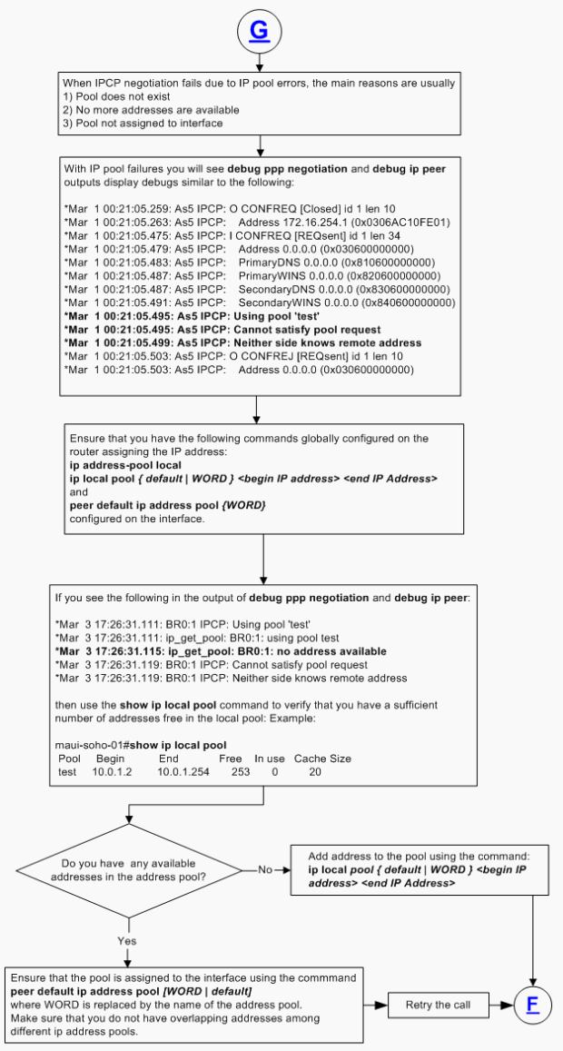
IP Pool Errors
Other PP Link Stability Issues
IP Layer 2 Bind Failures
Related Information
- Dial and Access Technology Support
- Understanding debug ppp negotiation Output
- Understanding and Configuring PPP CHAP Authentication
- PPP Authentication Using the ppp chap hostname and ppp authentication chap callin Commands
- Configuring and Troubleshooting PPP Password Authentication Protocol (PAP)
- Troubleshooting PPP (CHAP or PAP) Authentication
- Technical Support & Documentation - Cisco Systems
Revision History
| Revision | Publish Date | Comments |
|---|---|---|
1.0 |
18-Dec-2007 |
Initial Release |
Contact Cisco
- Open a Support Case

- (Requires a Cisco Service Contract)
 Feedback