Configuring the UBR 7100 in Bridge Mode
Available Languages
Contents
Introduction
This document details the configuration of the uBR7100 and Cisco Network Registrar for bridged network. Unlike the uBR7200, the uBR7100 can be used as a bridge. The bridging configuration consists of disabling IP routing, putting all of the interfaces in one bridge group, and configuring the cable interface. In this configuration, routing functions are done on the uBR7100's gateway/router. Since the routing functions are not done on the uBR7100 the configuration is streamlined. The bridging configuration puts the Cisco Network Registrar (CNR) server on the same network as the CMTS and the cable modems. CNR can reside behind the gateway/router, in which case the gateway is configured with an IP helper address to route broadcasts between the cable modems and the CNR.
Before You Begin
Conventions
For more information on document conventions, see the Cisco Technical Tips Conventions.
Prerequisites
The reader should have a basic understanding of the DOCSIS protocol and the Cisco IOS® command line on the uBR series routers.
Components Used
This configuration was developed and tested using the following:
-
Cisco uBR7100 Series Universal Broadband Routers running Cisco IOS version 12.10EC1
-
Cisco Network Registrar (CNR) running V 5.5
The information presented in this document was created from devices in a specific lab environment. All of the devices used in this document started with a cleared (default) configuration. If you are working in a live network, ensure that you understand the potential impact of any command before using it.
Background Theory
DOCSIS Basics
From the customer prospective DOCSIS is "plug and play," meaning that the cable modem is automatically configured from the network. When the cable is plugged in for the first time it will scan the downstream for a DOCSIS carrier. The modem will lock on to the first DOCSIS carrier it detects. The Upstream Channel Descriptor (UCD), which the cable modem reads from the downstream carrier, tells the modem how to transmit. The UCD has forward error correction (FEC) parameters, upstream frequency, modulation type, and symbol rate. Once the cable modem and the CMTS agree on the appropriate transmit level the modem will initiate the Dynamic Host Configuration Protocol (DHCP) process. The CNR server should hear the modems discover. The modem and the CNR server will exchange a series of messages that result in the modem having IP connectivity to the rest of the network. Once the modem has IP connectivity it can request Time of Day (ToD) and download its cable modem configuration file. Once the modem is configured it will send a registration request to the CMTS. If Baseline Privacy (BPI) is not enabled, the modem will register with the CMTS. If BPI is enabled, the modem will exchange encryption keys with the CMTS before being fully registered.
Bridging Mode Concept
In bridge mode all of the interfaces on the CMTS are configured in one bridge group. All interfaces associated with the bridge group are considered a part of the broadcast domain. This means that every device associated with one of these interfaces will hear broadcasts from all devices in the bridge group. This is convenient, since we can put the CNR server, the CMTS and the cable modems on the same network. When a cable modem broadcasts a DHCP discover the cable interface on the CMTS will forward it to the other interfaces in the bridge group. Since the CNR server is in the same bridge group it will hear the DHCP discover, and will respond with a DHCP offer. Subsequently, the modem will get ToD (from either an external server within the bridge group or the CMTS configured to be the ToD server) and its configuration file via Trivial File Transfer Protocol (TFTP), and register with the CMTS.
Configure
Note: To find additional information on the commands used in this document, use the Command Lookup Tool (registered customers only) .
Network Diagram
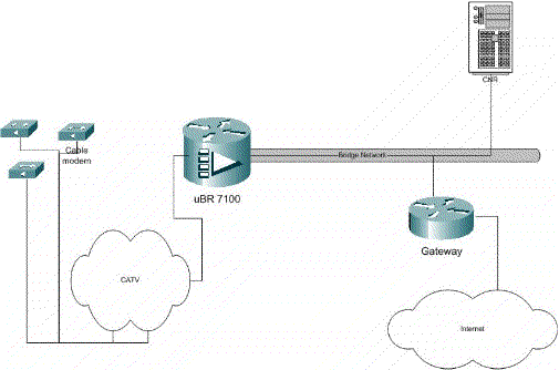
Figure 1
Configurations
This document uses the configurations shown below.
Configuration is broken into two parts: CNR server configuration, and the CMTS configuration. CNR is used to assign IP address via DHCP and give the modems the network connectivity information they need to access key elements of the network. In the CMTS configuration section, the uBR7100 is configured to register cable modems, and forward cable modem traffic to the rest of the LAN.
CNR Configuration
Configuring CNR consist of configuring policies and scopes for the cable modems and hosts. Policies are a list of DHCP options that get associated with a scope. Scopes are the IP address ranges which are to be assigned to a network.
Create a policy for the cable modems
-
Launch the CNR program and log in. Click on the DHCP server.
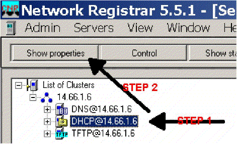
Figure 2
-
Click the SHOW PROPERTIES button on the Server Manager bar.
-
Click on the POLICIES tab. The policy in this example is named bb-ubr7114-1a.
-
Select NEW to create a new policy.
-
Under edit options add the following DHCP options:
-
dhcp-lease-time – This is the lease time in seconds. In this example, the lease time is 604800 (which is the number of seconds in a 7 day period). Note that in this example we have chosen to make those leases permanent by checking the lease are permanent box.
-
Routers – This is the IP gateway address. For this example the IP address is 14.66.1.1.
-
tftp-server – This is the address of the TFTP server. For this example the address is 14.66.1.1, which is the same as the CNR server's IP address. Note that the default directory for a served files on a Windows platform is Program Files\Network Registrar\Data\TFTP.
-
log-server – Address to log the DHCP server messages. In this example it is 14.66.1.1 (CNR server).
-
time-server – An external time server can be use. In our example the CMTS is acting as the time server 14.66.1.1.
-
timing-offset – This is the offset time from GMT in seconds. In this example the time offset is 18000.
-
packet-file-name – This option details the name of the cm file to be used. In our example gold.cm is used.
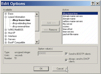
Figure 3
-
Create A Scope for the Cable Modems
-
Click on the DHCP server.
-
Click on the Add button the Server Manager Bar.
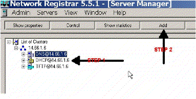
Figure 4
-
In the Add Scope box that pops up assign a name to the scope.
-
From the policy pull down select the policy that was created for this scope.
-
Enter your network in the Network blank. For this example the network number is 14.66.1.0.
-
Enter the subnet mask for your network in the Subnet Mask blank. For this example the subnet mask is 255.255.255.0.
-
Enter the first and last IP addresses in the Start Address and End Address boxes. In this example the first address would be 14.66.1.245, and the last would be 14.66.1.254.
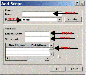
Figure 5
CMTS Configuration
The uBR7100 Series routers come equipped with a built in upconverter. An external upconverter can be used by running IF output from the DS0 port to the external upconverter. In this example the internal upconverter is used.
Note: For more information on configuring the integrated upconverter, refer to Setting the Integrated Upconverter in the Configuring the Cisco Cable Interface for the uBR7100 documentation.
Since this configuration was performed in a lab environment, the RF setup was quite simple. RF and setup measurements are beyond the scope of this document, and the reader is referred to Connecting and Configuring the Cable Headend documentation for proper RF setup and measurement and in accordance with DOCSIS specification (SP-RFI-IO5-991105 or later revision).
Cisco IOS Configuration
-
Configure a hostname on the CMTS.
-
Configure an enable password on the CMTS.
-
Configure a password on the vty lines.
-
Disable IP routing by executing the no ip routing command.
-
Configure an IP address on interface Fast Ethernet 0/0.
-
Configure bridging on the Fast Ethernet interface with the bridge-group command.
-
Disable spanning tree on Fast Ethernet 0/0 with the bridge-group spanning-disabled command.
-
On interface cable 1/0 configure the upconverter:
-
Turn on the up converter by executing a no cable downstream rf-shutdown.
-
Set the downstream frequency with the cable downstream frequency command. Keep in mind that the frequency is in Hertz. You must use a standard NTSC CATV channel frequency.
-
Set the downstream channel power with the cable downstream rf-power command.
-
Activate the line card by executing a no shutdown.
-
Activate the upstream by executing a no cable upstream 0 shutdown.
-
Set the upstream frequency with the cable upstream frequency command.
-
Set the upstream channel width using the cable upstream channel-width command.
-
-
Configure bridging on Interface Cable 1/0.
-
Disable spanning tree on Cable 1/0.
| Device Name (Cisco 1600 Router) |
|---|
version 12.1
       no service pad
       service timestamps debug datetime msec localtime
       service timestamps log datetime
       no service password-encryption
       enable password cisco
       service udp-small-servers max-servers no-limit
       service tcp-small-servers max-servers no-limit
       !
       hostname ubr7100
       !
       cable time-server
       !
       clock timezone PST -9
       clock calendar-valid
       ip subnet-zero
       no ip routing
!--Disable IP routing, enabled by default

       no ip domain-lookup
       !
       interface FastEthernet0/0
       ip address 14.66.1.2 255.255.255.0
       no ip route-cache
       no ip mroute-cache
       no keepalive
       duplex half
       speed auto
       no cdp enable
       bridge-group 1
       bridge-group 1 spanning-disabled
       !
       interface FastEthernet0/1
       ip address 14.66.1.2 255.255.255.0
       no ip route-cache
       no ip mroute-cache
       shutdown
!-- Not connected

       duplex auto
       speed 10
       no cdp enable
       bridge-group 1
       bridge-group 1 spanning-disabled
       !
       interface Cable1/0
       ip address 14.66.1.2 255.255.255.0
       no ip route-cache
       no ip mroute-cache
       load-interval 30
       no keepalive
       cable downstream annex B
       cable downstream modulation 256qam
!-- for a non-lab environment 64 QAM is suggested

       cable downstream interleave-depth 32
       cable downstream frequency 525000000
!-- This is a required line for the uBR7100

       no cable downstream rf-shutdown
!-- This line turns on the internal upconverter.

       cable downstream rf-power 55
!-- This line specifies the CMTS's transmit level.

       cable upstream 0 frequency 17808000
!-- This line configures the frequency specified in the UCD

       cable upstream 0 power-level 0
       cable upstream 0 channel-width 3200000
       no cable upstream 0 shutdown
!-- This line turns the upstream receiver on.

       bridge-group 1
!-- This line configure bridging on the cable interface.

       bridge-group 1 subscriber-loop-control
       bridge-group 1 spanning-disabled
       !
       ip default-gateway 14.66.1.1
       ip classless
       no ip http server
       !
       no cdp run
       alias exec scm show cable modem
       !
       line con 0
       exec-timeout 0 0
       privilege level 15
       length 0
       line aux 0
       line vty 0 4
       password cisco
       no login
       !
end |
Verify
Note: Certain show commands are supported by the Output Interpreter Tool (registered customers only) , which allows you to view an analysis of show command output.
show cable modem will display all the modems that have contacted the CMTS, and information relating to the modem's state in the registration process. The output of this command is a snap-shot. In theory, if this command is executed in series you can see a modem progress from init(r1) to online status. In the example below BPI is turned on.
ubr7100#show cable modem
 Interface Prim Online Timing Rec QoS CPE IP address MACaddress
 Sid State Offset Power
 Cable1/0/U0 1 online(pt) 1551 0.00 5 0  14.66.1.245 0050.7366.1e69
 Cable1/0/U0 2 online(pt) 1920 -0.75 5 0 14.66.1.252 0006.2854.72db
 Cable1/0/U0 3 online(pt) 1549 0.25 5 0  14.66.1.250 0050.7366.1e6d
 Cable1/0/U0 4 online(pt) 1548 -0.25 5 0 14.66.1.251 0050.7366.1e41
Lease Verification in CNR
To confirm that IP addresses are being handed to a cable modem, go to the Lease tab for the scope. Confirm that IP addresses are being handed out. This section displays the IP block, and its lease information. The output is a snap-shot. To update the information, hit the Refresh List Button.
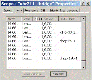
Figure 6
If the modems attached to your CMTS are not registering, please refer to Troubleshooting uBR Cable Modems Not Coming Online.
Related Information
Contact Cisco
- Open a Support Case

- (Requires a Cisco Service Contract)


 Feedback