Building a Nexus 9000 VXLAN Shared Border Multisite Deployment using DCNM
Available Languages
Download Options
Bias-Free Language
The documentation set for this product strives to use bias-free language. For the purposes of this documentation set, bias-free is defined as language that does not imply discrimination based on age, disability, gender, racial identity, ethnic identity, sexual orientation, socioeconomic status, and intersectionality. Exceptions may be present in the documentation due to language that is hardcoded in the user interfaces of the product software, language used based on RFP documentation, or language that is used by a referenced third-party product. Learn more about how Cisco is using Inclusive Language.
Contents
Introduction
This document is to explain how to deploy a Cisco Nexus 9000 VXLAN Multisite Deployment using shared border model using DCNM 11.2 version.
Topology

Details of The topology
DC1 and DC2 are two datacenter locations which are running vxlan;
DC1 and DC2 Border Gateways are having physical connections to the shared borders;
Shared borders have the External connectivity(eg; Internet); so the VRF lite connections are terminated on shared borders and a default route is injected by the shared borders to Border Gateways in each site
Shared borders are configured in vPC(This is a requirement when the fabric is deployed using DCNM)
Border Gateways are configured in Anycast mode
Components Used:
Nexus 9ks running 9.3(2)
DCNM running 11.2 Version
The information in this document was created from the devices in a specific lab environment. All of the devices used in this document started with a cleared (default) configuration. If your network is live, make sure that you understand the potential impact of any command.
High Level Steps
1) Considering that this document is based on Two Datacenters utilizing vxlan multisite feature, Two Easy Fabrics have to be created
2) Create Another easy Fabric for the Shared Border
3) Create MSD and move DC1 and DC2
4) Create External Fabric
5) Create Multisite Underlay and Overlay(For East/West)
6) Create VRF Extension Attachments on Shared borders
Step 1: Creation of Easy Fabric for DC1
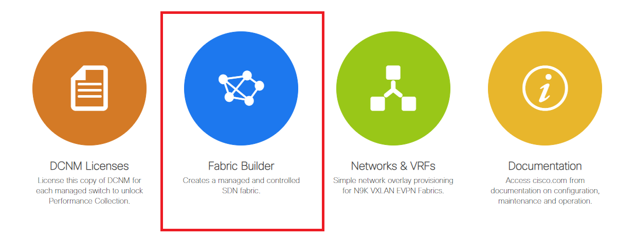
- Login to the DCNM and from the Dashboard, Select the option-> "Fabric Builder"
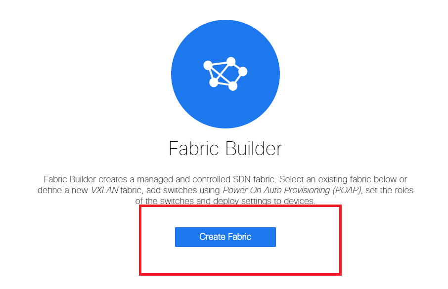
- Select the "create fabric" option
- Next is to provide the fabric name, template and then multiple tabs will open up which will need details like ASN, Fabric Interface Numbering, Any Cast Gateway MAC(AGM)
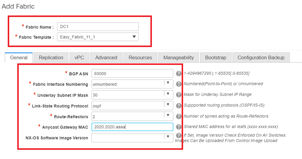
# Fabric Interfaces(which are the Spine/Leaf interfaces) can be "unnumbered" or point to point; If unnumbered is used, the IP addresses required are less(as the IP address is that of the unnumbered loopback)
# AGM is used by the Hosts in the Fabric as the Default Gateway MAC address; This will be the same on all Leaf switches which are the Default Gateways
- Next is to set the Replication mode
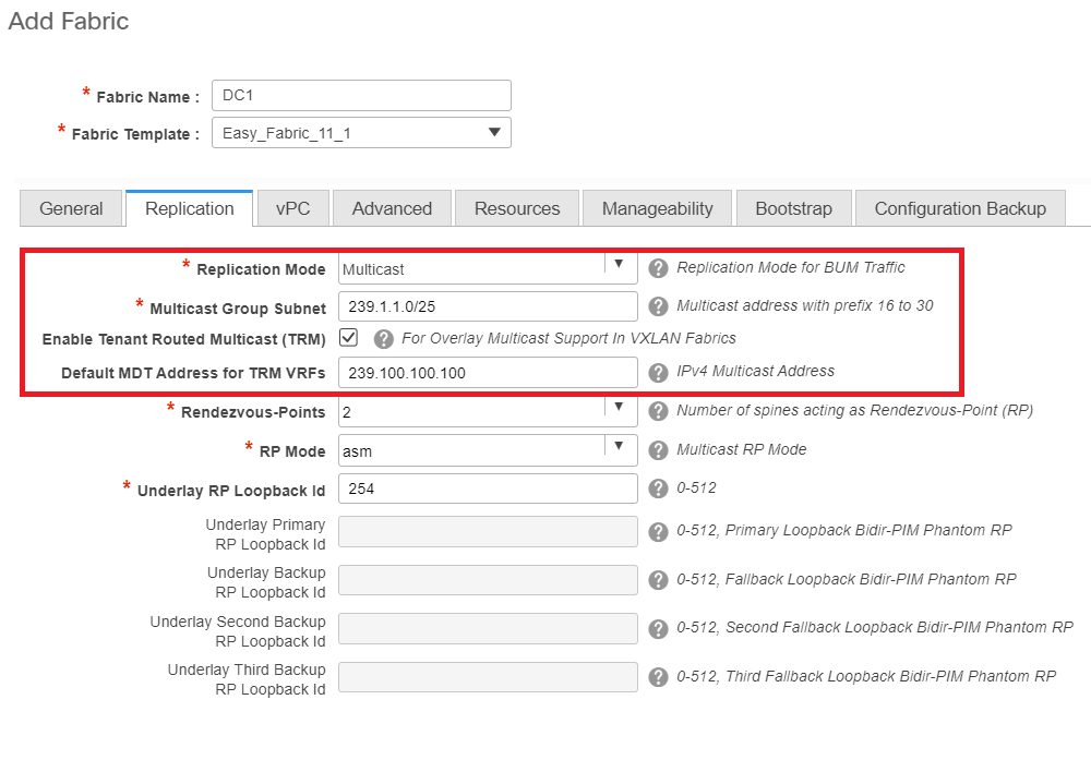
# Replication mode selected here can be either multicast or IR-Ingress Replication; IR will replicate any incoming BUM traffic within a vxlan vlan in a unicast fashion to other VTEPs which is also called Head end replication whereas Multicast mode will send the BUM traffic with an outer destination IP address as that of the Multicast group defined for each Networks up to the Spine and Spines will do the multicast replication based off of the Outer destination IP address' OIL to other VTEPs
# Multicast Group subnet-> Required to replicate the BUM traffic(like ARP request from a host)
# If TRM is required to be enabled, select the check box against the same and provide the MDT address for the TRM VRFs.
- Tab for "vPC" is left at default; If any changes are required for the backup SVI/VLAN, those can be defined here
- Advanced tab is the Next Section
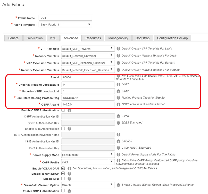
# Site ID mentioned here is auto-populated on this DCNM Version which is derived from the ASN that is defined underneath the "General" tab
# Fill up/Modify other fields which are relevant
- Resources tab is the Next one which would need the IP addressing Scheme for Loopbacks, Underlays

# Layer 2 VXLAN VNI Range-> These are the VNIDs which will be later mapped to Vlans(Will show it further down)
# Layer 3 VXLAN VNI Range-> These are the Layer 3 VNIDs that will also be later mapped to layer 3 VNI Vlan to Vn-segment
- Other tabs are not shown here; but do Fill up the other tabs if needed;
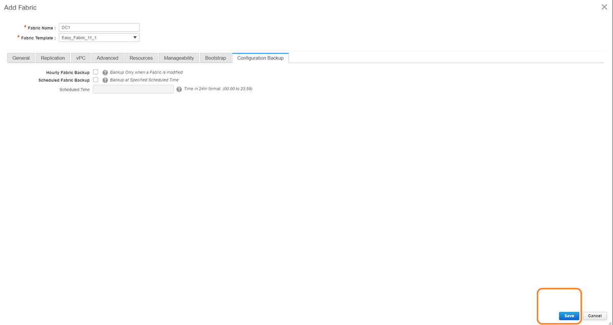
- Once you save, the fabric builder page will show the Fabric(From DCNM-> Control-> Fabric Builder
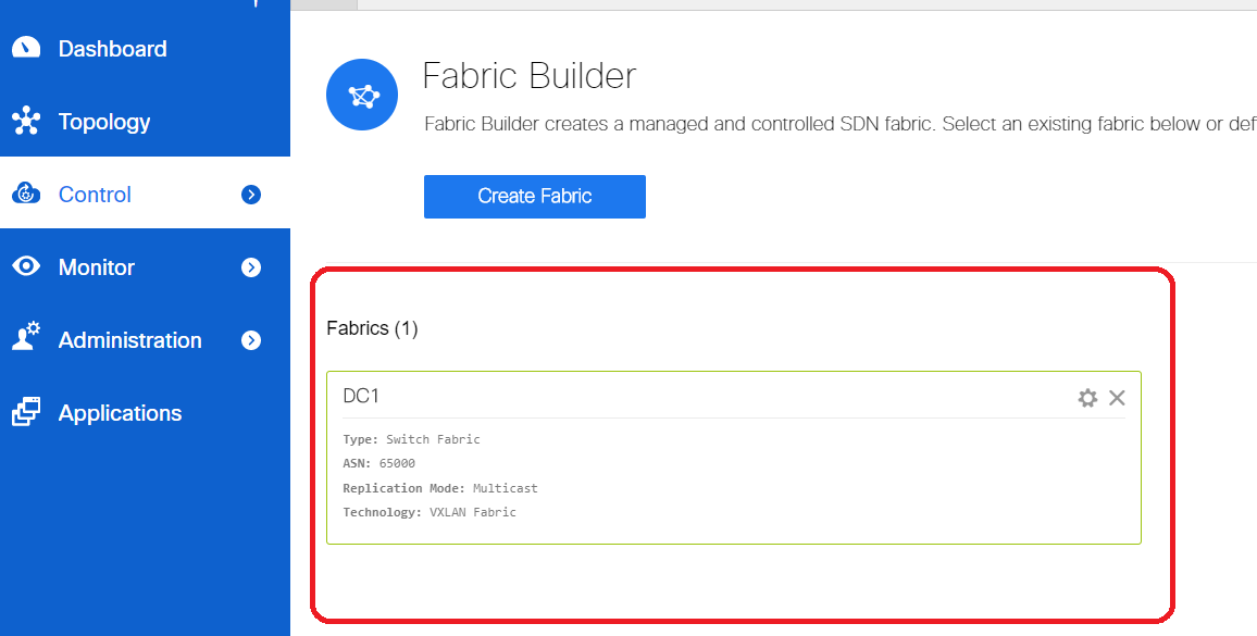
# This section shows the full list of Fabrics, ASN, Replication modes for each of the Fabrics
- Next step is to Add switches onto the DC1 Fabric
Step 2: Add switches into the DC1 Fabric
Click on DC1 in the diagram above and that would give the option to add switches.

- Provide IP addresses and credentials of the switches that needs to be imported to DC1 Fabric(Per topology listed in the beginning of this document, DC1-VTEP, DC1-SPINE, DC1-BGW1 & DC1-BGW2 are part of DC1)
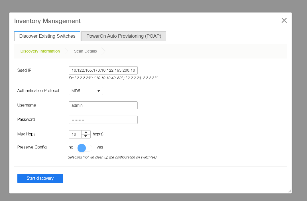
# Since this is a Greenfield deployment, Note that the "preserve config" option is selected as "NO"; which will delete all the configurations of the boxes while doing the import and also will reload the switches
# Select the "Start discovery" so that DCNM will start discovering the switches based on the IP addresses provided in the "seed IP" column
- Once the DCNM finishes discovering the switches, the IP addresses along with the hostnames will be listed in the Inventory management

# Select the relevant switches and then Click on "Import into fabric"
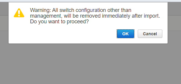
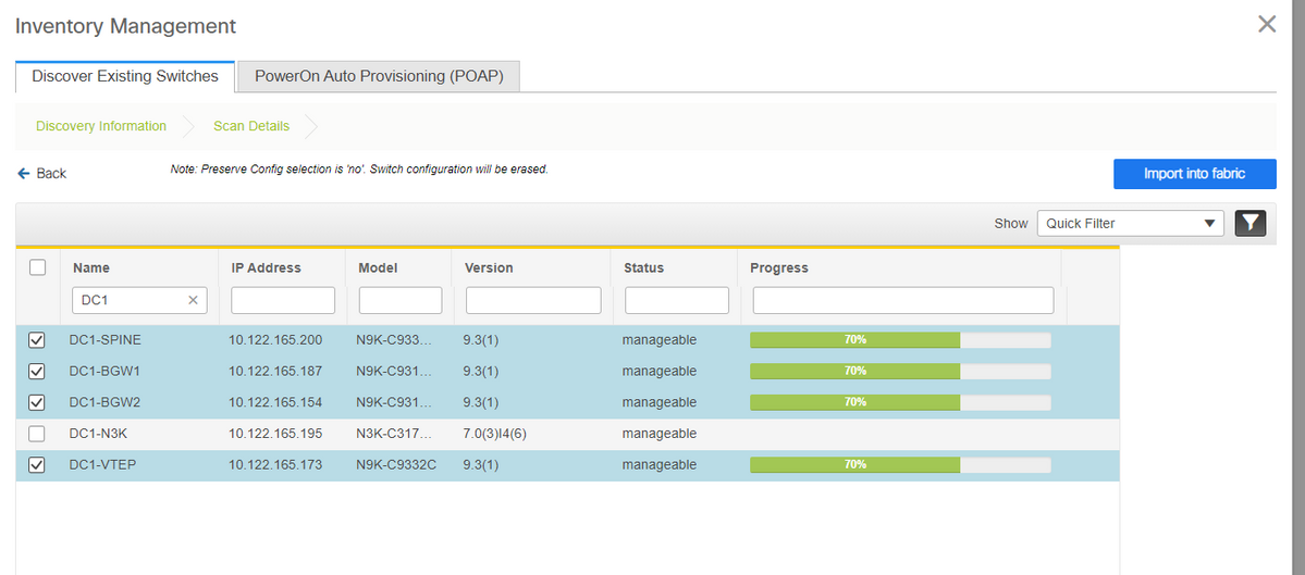
# Once the import is done, the topology under fabric builder may look like below;
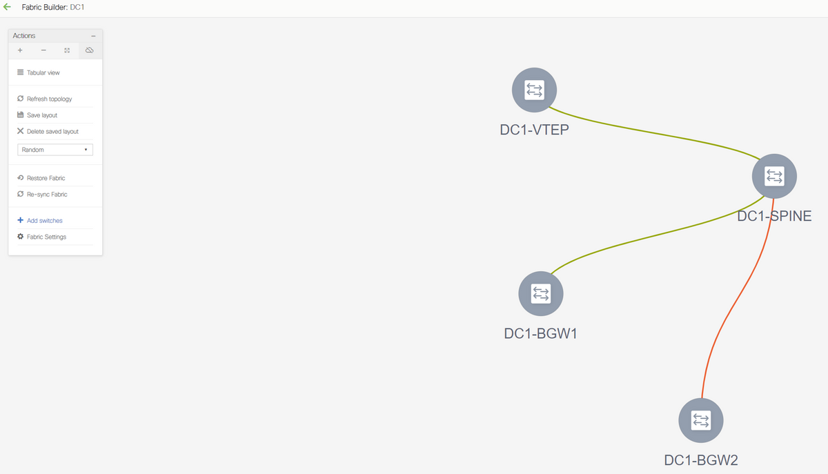
# The switches can be moved around by clicking on one switch and aligning it to the right location within the diagram
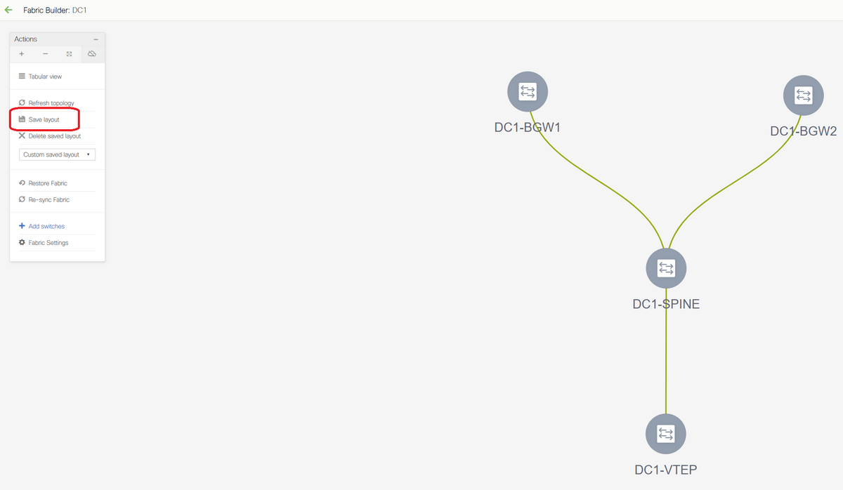
# Select the "save layout" section after rearranging the switches in the order the layout is needed
- Setting roles for all switches
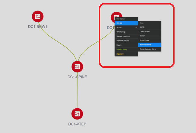
# Right Click each of the switches and set the right role; Here, DC1-BGW1 & DC1-BGW2 are the border gateways
# DC1-SPINE-> Will be set to role- Spine, DC1-VTEP-> Will be set to role-Leaf
- Next Step is to save and Deploy
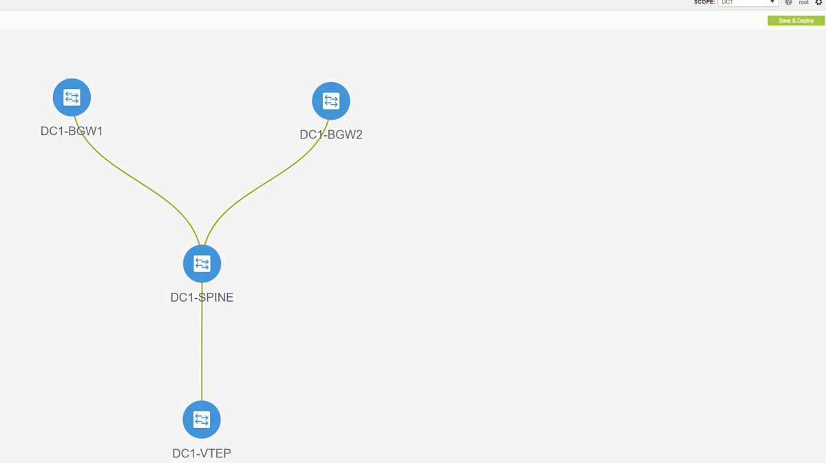
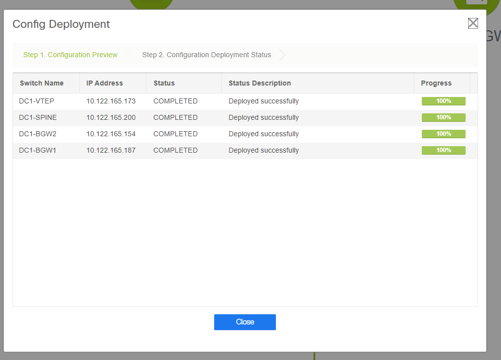
# DCNM Will now list the switches and also will have the preview of the configurations that DCNM Is going to push to all switches.


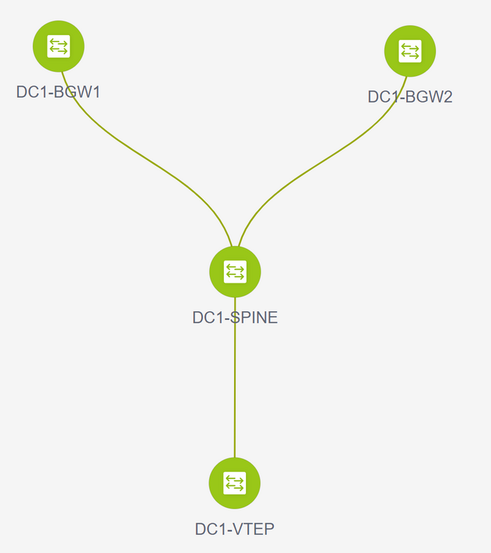
# Once it is successful, the status will reflect and also the switches will be shown in Green
Step 3: Configuration of Networks/VRFs
- Configuration of Networks/VRFs
# Select DC1 Fabric(from the top right drop down), Control > VRFs

# Next is to Create VRF

# 11.2 DCNM Version is auto-populating the VRF ID; If its Different, type in the one that you need and select the "Create VRF"
# Here, the Layer 3 VNID used is 1001445
- Next step is to create the Networks
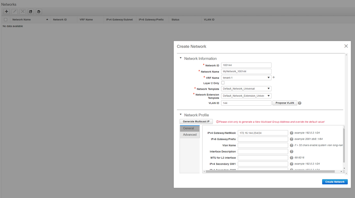
# Provide the Network ID(Which is the Layer 2 Vlans' corresponding VNID
# Provide the VRF that the SVI should be part of; By default, DCNM 11.2 populates the VRF Name to the previously created one; Change as needed
# Vlan ID will be Layer 2 VLan that is mapped to this particular VNID
# IPv4 Gateway-> This is the Anycast Gateway IP address which will be configured on the SVI and will be the same for all the VTEPs within the fabric
- Advanced Tab has extra rows that need to be filled if eg; DHCP Relay is using;

# Once the fields are populated, click on "create Network".
# Create any other Networks that are required to be part of this fabric;
- At this moment, VRF and Networks are just defined in DCNM; but not pushed from DCNM to the switches in the fabric. This can be verified using below

# Status will be in "NA" if this is NOT Deployed to the switches. Since this is a multisite and involves Border Gateways, Deployment of Networks/VRFs will be discussed further down.
Step 4: Repeat the same steps for DC2
- Now that the DC1 is fully defined, will carry out the same procedure for DC2 as well
- Once DC2 is fully defined, it will look like below

Step 5: Creation of easy fabric for Shared borders
- This is where another easy fabric is created which will include the shared borders which are in vPC
- Note that the Shared borders while deploying via DCNM Should be configured as vPC as otherwise, the inter-switch links will be shut down after a "re-sync" operation is performed on DCNM
- The Switches in Shared borders are to be set with the role of "Border"
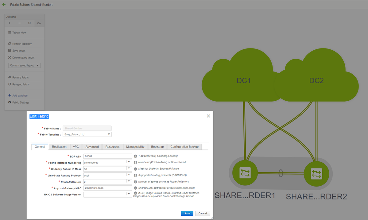
# VRFs are also created like it was for DC1 and DC2 fabrics
# Networks are not required on a shared border as the Shared border will not have any Layer 2 Vlans/VNIDs; Shared borders are not a tunnel termination for any East/West Traffic from DC1 to DC2; Only the Border Gateways would play a role in terms of vxlan encapsulation/decapsulation for East/West DC1<>DC2 traffic
Step 6- Creation of MSD and Moving DC1 and DC2 Fabrics
Go to Fabric builder and create new Fabric and use the template -> MSD_Fabric_11_1


# Note that Multi-site Overlay IFC Deployment Method has to be "centralized_To_Route_Server"; Here, the Shared borders are considered as Route servers and so this option is used from the drop down
# Within the "Multisite Route Server List"; Here, find out the Loopback IP addresses of Loopback0(which is the Routing loopback) on shared border and fill it up
# ASN is the one on shared border(Refer diagram on top of this document for more details); For the purpose of this document, both the shared borders are configured in the same ASN; Fill in accordingly
- Next tab is where the Multisite Loopback IP range is provided as shown below
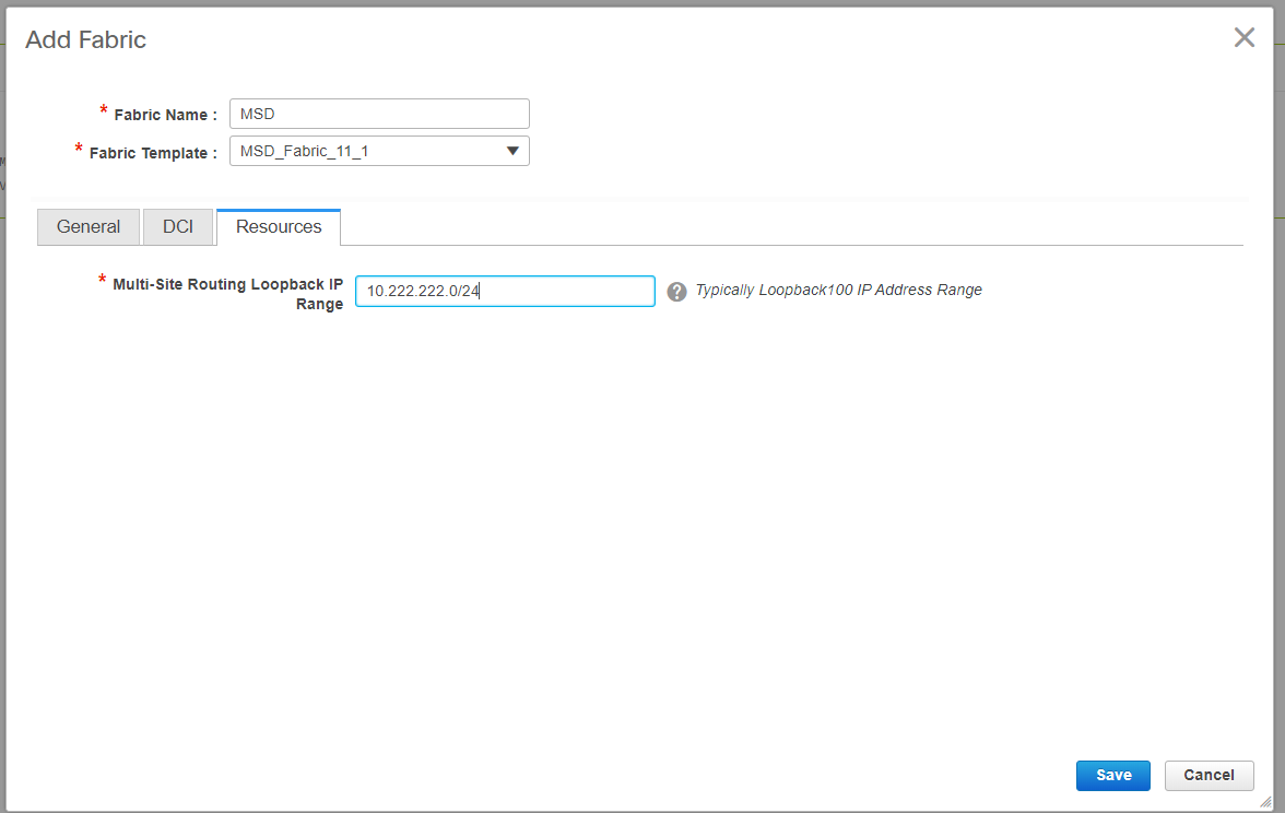
# Once all the fields are populated, click the "save" button and a new Fabric will be created with the template-> MSD
# Next is to move the DC1 and DC2 fabrics to this MSD
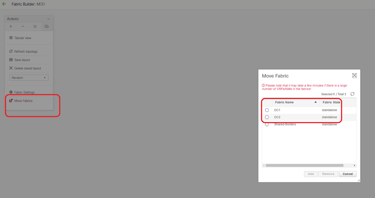
# After the fabric move, it looks like below
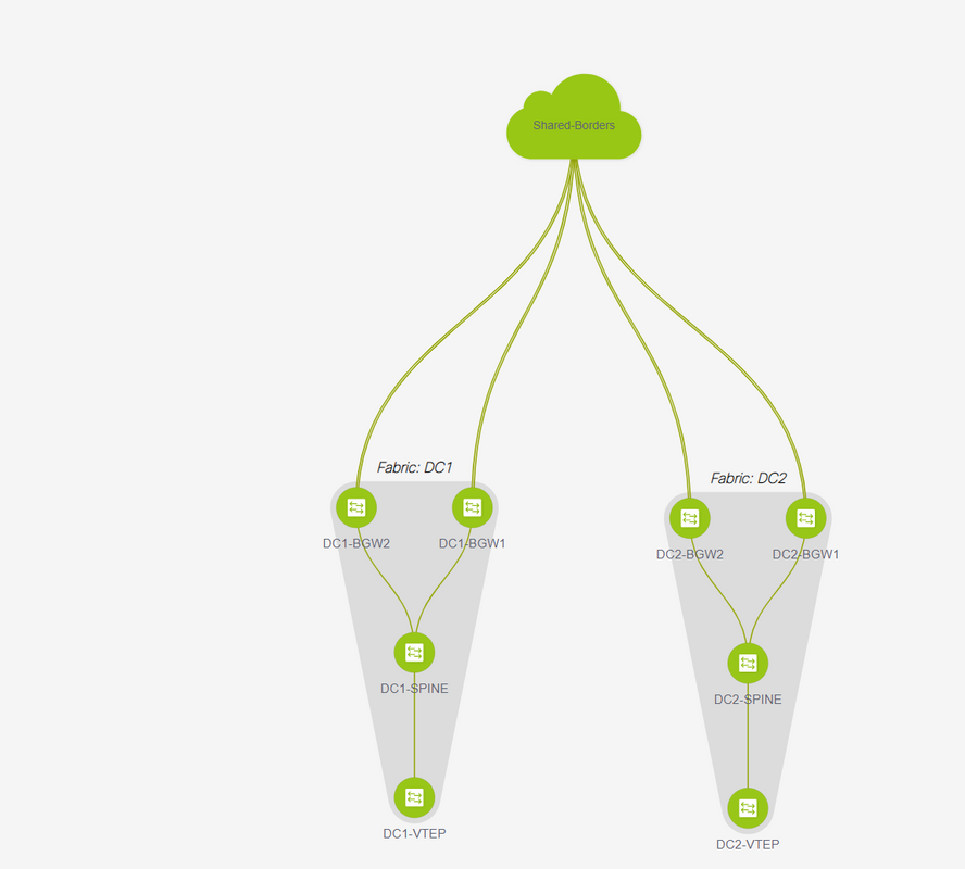
# Once done, click on the "save&Deploy" button which will push the required configurations as far as multisite is concerned to the border Gateways

Step 7: Creation of External Fabric
# Create External Fabric and add the external router to it as shown below;
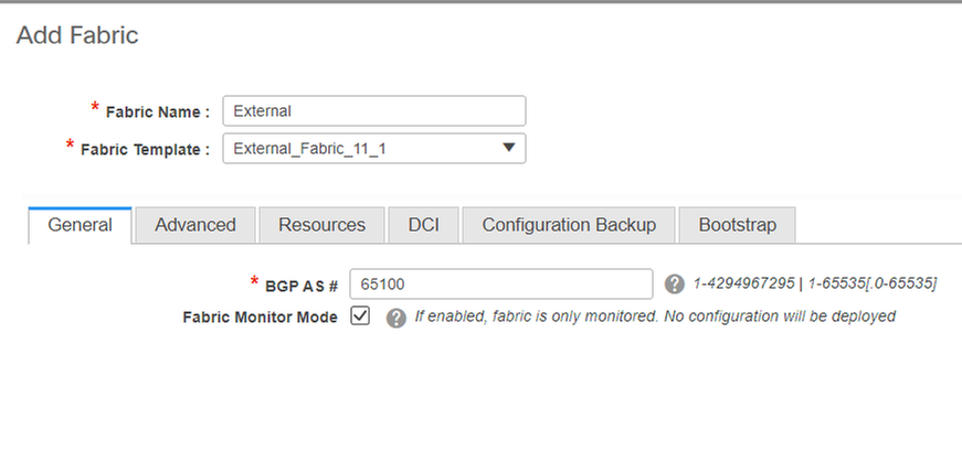
# Name the fabric and use the template-> "External_Fabric_11_1";
# Provide the ASN
# At the end, the various fabrics will look like below

Step 8: eBGP Underlay for loopback reachability between BGWs(iBGP Between Shared borders as well)
# Shared borders run eBGP l2vpn evpn with the Border Gateways and VRF-LITE connections towards the external router
# Before Forming eBGP l2vpn evpn with the loopbacks, it is required to make sure that the loopbacks are reachable via some method; In this example, we are using eBGP IPv4 AF from BGWs to Shared borders and then advertise the loopbacks to further form the l2vpn evpn neighborship.
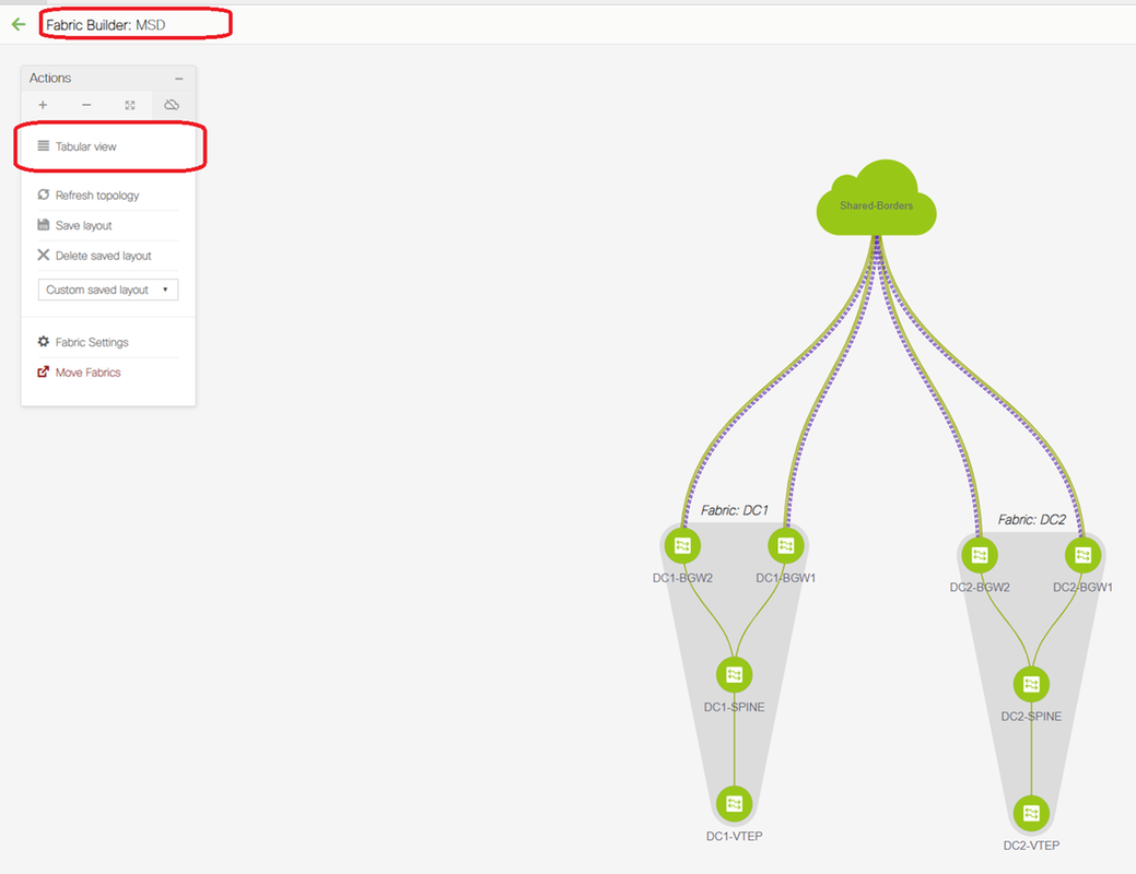
# Once the MSD fabric is selected, switch to "tabular view"


# Select the "inter-fabric" and use the "Multisite_UNDERLAY"
# We are here trying to form an IPv4 BGP Neighborship with the Shared border router; So select the switches and interfaces accordingly.
# Note that If CDP is detecting the neighbor from DC1-BGW1 to SB1, it is only required to provide the IP addresses here in this section and that will effectively configure the IP addresses on the relevant interfaces after performing "save & Deploy"
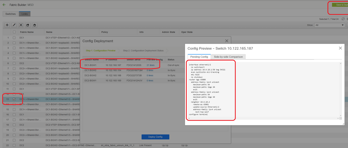
# Once Save and deploy is selected, the required configuration lines are propagated for DC1-BGW1; Same step will have to be performed after selecting the "Shared border" fabric too.

# From CLI, the same can be verified using the command below;
DC1-BGW1# show ip bgp sum
BGP summary information for VRF default, address family IPv4 Unicast
BGP router identifier 10.10.10.1, local AS number 65000
BGP table version is 11, IPv4 Unicast config peers 1, capable peers 1
2 network entries and 2 paths using 480 bytes of memory
BGP attribute entries [1/164], BGP AS path entries [0/0]
BGP community entries [0/0], BGP clusterlist entries [0/0]

Neighbor        V    AS MsgRcvd MsgSent   TblVer  InQ OutQ Up/Down  State/PfxRcd
10.4.10.2       4 65001       6       7       11    0    0 00:00:52 0
# Note that the "save&Deploy" has to be done on the DC1 fabric as well(Select the drop down for DC1 and then perform the same) so that the Relevant IP addressing, BGP configurations are propagated to the switches in DC1(which are the Border Gateways);
# Also, the multisite underlay has to be created from DC1-BGWs, DC2-BGWs to Shared borders; so, same steps as above have to be done for the same too.
# At the end, Shared borders will have eBGP IPv4 AF neighborship with all BGWs in DC1 and DC2 as below;
SHARED-BORDER1# sh ip bgp sum
BGP summary information for VRF default, address family IPv4 Unicast
BGP router identifier 10.10.100.1, local AS number 65001
BGP table version is 38, IPv4 Unicast config peers 4, capable peers 4
18 network entries and 20 paths using 4560 bytes of memory
BGP attribute entries [2/328], BGP AS path entries [2/12]
BGP community entries [0/0], BGP clusterlist entries [0/0]

Neighbor        V    AS MsgRcvd MsgSent   TblVer  InQ OutQ Up/Down  State/PfxRcd
10.4.10.1       4 65000    1715    1708       38    0    0    1d03h 5
10.4.10.6       4 65000    1461    1458       38    0    0    1d00h 5
10.4.10.18      4 65002    1459    1457       38    0    0    1d00h 5
10.4.10.22      4 65002    1459    1457       38    0    0    1d00h 5

SHARED-BORDER2# sh ip bgp sum
BGP summary information for VRF default, address family IPv4 Unicast
BGP router identifier 10.10.100.2, local AS number 65001
BGP table version is 26, IPv4 Unicast config peers 4, capable peers 4
18 network entries and 20 paths using 4560 bytes of memory
BGP attribute entries [2/328], BGP AS path entries [2/12]
BGP community entries [0/0], BGP clusterlist entries [0/0]

Neighbor        V    AS MsgRcvd MsgSent   TblVer  InQ OutQ Up/Down  State/PfxRcd
10.4.10.10      4 65000    1459    1458       26    0    0    1d00h 5
10.4.10.14      4 65000    1461    1458       26    0    0    1d00h 5
10.4.10.26      4 65002    1459    1457       26    0    0    1d00h 5
10.4.10.30      4 65002    1459    1457       26    0    0    1d00h 5
# Above is the pre-requisite prior building the l2vpn evpn neighborship from BGWs to Shared borders(Note that its not mandatory to use BGP; any other mechanism to exchange loopback prefixes would do); At the end, the base requirement is that all loopbacks(of Shared borders, BGWs) should be reachable from all BGWs
# Please also note that an iBGP IPv4 AF neighborship needs to be established between Shared borders; As of Today, DCNM do not have an option to build an iBGP between shared borders using a template/drop down; For that, a Freeform configuration has to be done which is shown below;
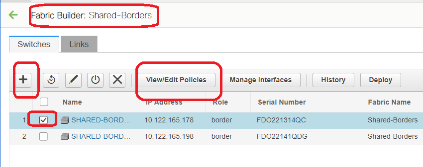
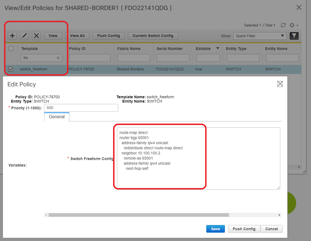
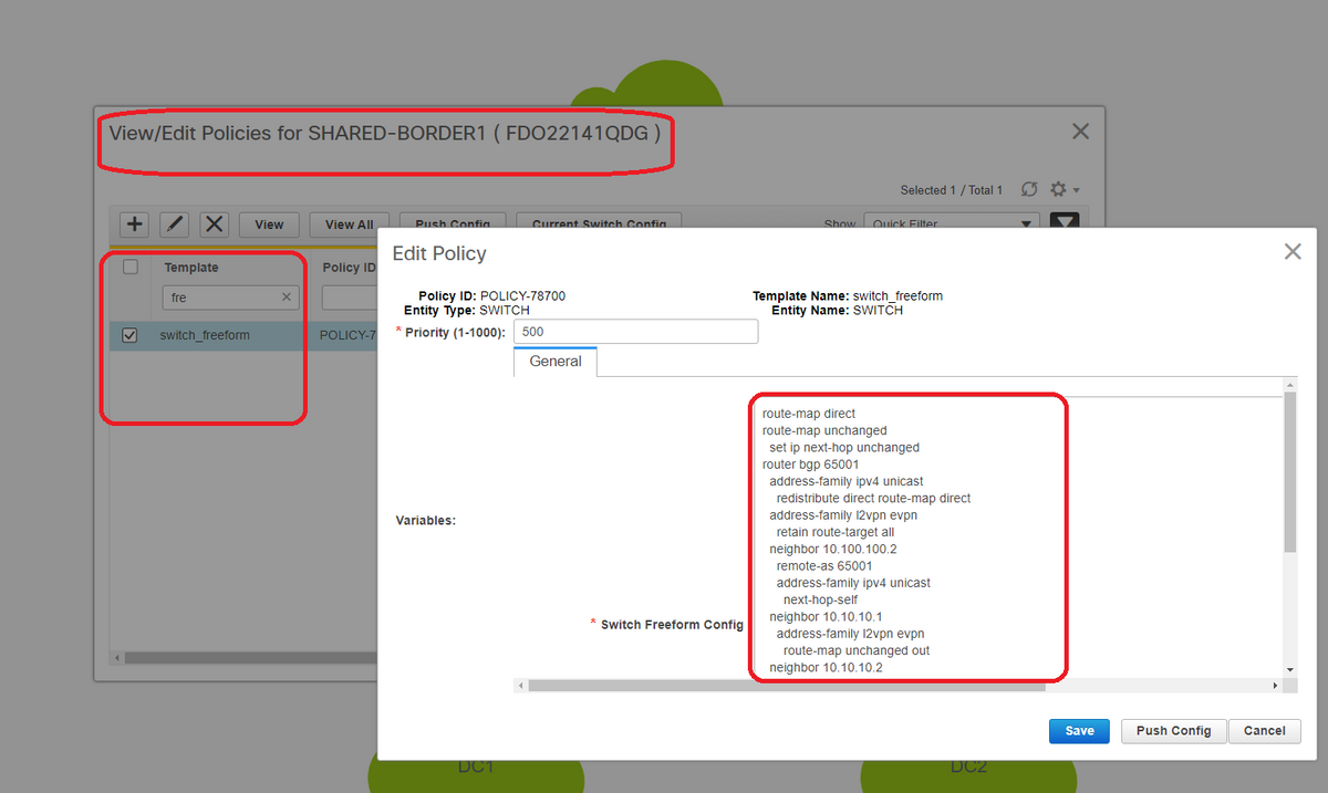
# Find the IP addresses which are configured on the Backup SVI of shared borders; As shown above, freeform is added on Shared-border1 switch and the iBGP neighbor specified is that of the Shared-border2(10.100.100.2)
# Note that while providing the configurations within the freeform in DCNM, provide the correct spacing after each commands(leave even number of spaces; meaning, after router bgp 65001, provide two spaces and then give the neighbor <> command and so on)
# Also make sure to perform a redistribute direct for the direct routes(loopback routes) in BGP or some other form to advertise the loopbacks; in the example above, a route-map direct is created to match all direct routes and then redistribute direct is done within the IPv4 AF BGP
# Once the configuration is "saved and deployed" from DCNM, iBGP neighborship is formed as shown below;
SHARED-BORDER1# sh ip bgp sum
BGP summary information for VRF default, address family IPv4 Unicast
BGP router identifier 10.10.100.1, local AS number 65001
BGP table version is 57, IPv4 Unicast config peers 5, capable peers 5
18 network entries and 38 paths using 6720 bytes of memory
BGP attribute entries [4/656], BGP AS path entries [2/12]
BGP community entries [0/0], BGP clusterlist entries [0/0]

Neighbor        V    AS MsgRcvd MsgSent   TblVer  InQ OutQ Up/Down  State/PfxRcd
10.4.10.1       4 65000    1745    1739       57    0    0    1d04h 5
10.4.10.6       4 65000    1491    1489       57    0    0    1d00h 5
10.4.10.18      4 65002    1490    1487       57    0    0    1d00h 5
10.4.10.22      4 65002    1490    1487       57    0    0    1d00h 5
10.100.100.2    4 65001      14       6       57    0    0 00:00:16 18 # iBGP neighborship from shared border1 to shared border2
# With above step, the multisite underlay is fully configured.
# Next Step is to build the multisite overlay;
Step 9: Building Multisite Overlay from BGWs to Shared borders
# Note that, here Shared borders are also the route servers
# Select the MSD and then go to the "Tabular view" where a new link can be created; From there, a new multisite overlay link has to be created and the relevant IP addresses will have to provided with the correct ASN as below; This step has to be done for all the l2vpn evpn neighbors(which is from every BGW to Every Shared border)
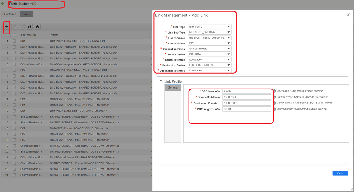
# Above is one example; Perform the same for all other multisite Overlay Links and at the end, the CLI will look like below;
SHARED-BORDER1# sh bgp l2vpn evpn summary
BGP summary information for VRF default, address family L2VPN EVPN
BGP router identifier 10.10.100.1, local AS number 65001
BGP table version is 8, L2VPN EVPN config peers 4, capable peers 4
1 network entries and 1 paths using 240 bytes of memory
BGP attribute entries [1/164], BGP AS path entries [0/0]
BGP community entries [0/0], BGP clusterlist entries [0/0]

Neighbor        V    AS MsgRcvd MsgSent   TblVer  InQ OutQ Up/Down  State/PfxRcd
10.10.10.1      4 65000      21      19        8    0    0 00:13:52 0
10.10.10.2      4 65000      22      20        8    0    0 00:14:14 0
10.10.20.1      4 65002      21      19        8    0    0 00:13:56 0
10.10.20.2      4 65002      21      19        8    0    0 00:13:39 0

SHARED-BORDER2# sh bgp l2vpn evpn summary
BGP summary information for VRF default, address family L2VPN EVPN
BGP router identifier 10.10.100.2, local AS number 65001
BGP table version is 8, L2VPN EVPN config peers 4, capable peers 4
1 network entries and 1 paths using 240 bytes of memory
BGP attribute entries [1/164], BGP AS path entries [0/0]
BGP community entries [0/0], BGP clusterlist entries [0/0]

Neighbor        V    AS MsgRcvd MsgSent   TblVer  InQ OutQ Up/Down  State/PfxRcd
10.10.10.1      4 65000      22      20        8    0    0 00:14:11 0
10.10.10.2      4 65000      21      19        8    0    0 00:13:42 0
10.10.20.1      4 65002      21      19        8    0    0 00:13:45 0
10.10.20.2      4 65002      22      20        8    0    0 00:14:15 0
Step 10: Deploying Networks/VRFs on both sites
# As we have finished the multisite Underlay and Overlay, Next step is to deploy the Networks/VRFs on all devices;
# Starting with VRFs on Fabrics-> DC1, DC2 and Shared borders.

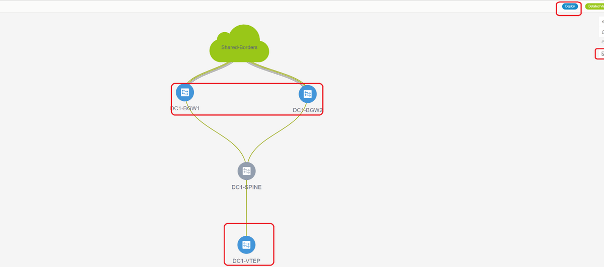
# Once the VRF View is selected, click on "continue"; This will list out the devices in the topology
# Since the VRF has to be deployed to multiple switches(including Border Gateways and Leaf), select the Checkbox at the far right and then select the switches which has the same role at one time; eg; DC1-BGW1 and DC1-BGW2 can be selected at one time and then save both the switches; After this, select the leaf switches which are applicable(here it would be DC1-VTEP)

# As seen above, When the "Deploy" option is selected, all the switches which were previously selected will start the deployment and will finally turn green if the deploy was successful.
# Same steps will have to be performed for deploying Networks;

# If multiple networks are created, keep in mind to navigate to the subsequent tabs to select the networks before deploying

# The status will now turn to "DEPLOYED" from "NA" and the switch' CLI below can be used in order to verify the deployments
DC1-VTEP# sh nve vni
Codes: CP - Control Plane        DP - Data Plane
       UC - Unconfigured         SA - Suppress ARP
       SU - Suppress Unknown Unicast
       Xconn - Crossconnect
       MS-IR - Multisite Ingress Replication

Interface VNI      Multicast-group   State Mode Type [BD/VRF]      Flags
--------- -------- ----------------- ----- ---- ------------------ -----
nve1      100144   239.1.1.144       Up    CP   L2 [144]                # Network1 which is VLan 144 mapped to VNID 100144
nve1      100145   239.1.1.145       Up    CP   L2 [145]                # Network2 Which is Vlan 145 mapped to VNID 100145
nve1      1001445  239.100.100.100   Up    CP   L3 [tenant-1]           # VRF- tenant1 which is mapped to VNID 1001445
DC1-BGW1# sh nve vni
Codes: CP - Control Plane        DP - Data Plane
       UC - Unconfigured         SA - Suppress ARP
       SU - Suppress Unknown Unicast
       Xconn - Crossconnect
       MS-IR - Multisite Ingress Replication

Interface VNI      Multicast-group   State Mode Type [BD/VRF]      Flags
--------- -------- ----------------- ----- ---- ------------------ -----
nve1      100144   239.1.1.144       Up    CP   L2 [144]           MS-IR
nve1      100145   239.1.1.145       Up    CP   L2 [145]           MS-IR
nve1      1001445  239.100.100.100   Up    CP   L3 [tenant-1]
# Above is from BGW as well; so in short, all switches which we had selected earlier in the step will be deployed with the Networks and VRF
# Same steps have to be carried out for the Fabric DC2, Shared border as well. Keep in mind that the Shared borders DO NOT need any networks or layer 2 VNIDs; only L3 VRF is required.
Step 11: Creating downstream Trunk/Access ports on Leaf Switches/VTEP
# In this Topology, Ports Eth1/2 and Eth1/1 from DC1-VTEP and DC2-VTEP respectively are connected to the hosts; so Moving those as trunk ports in DCNM GUI as shown below

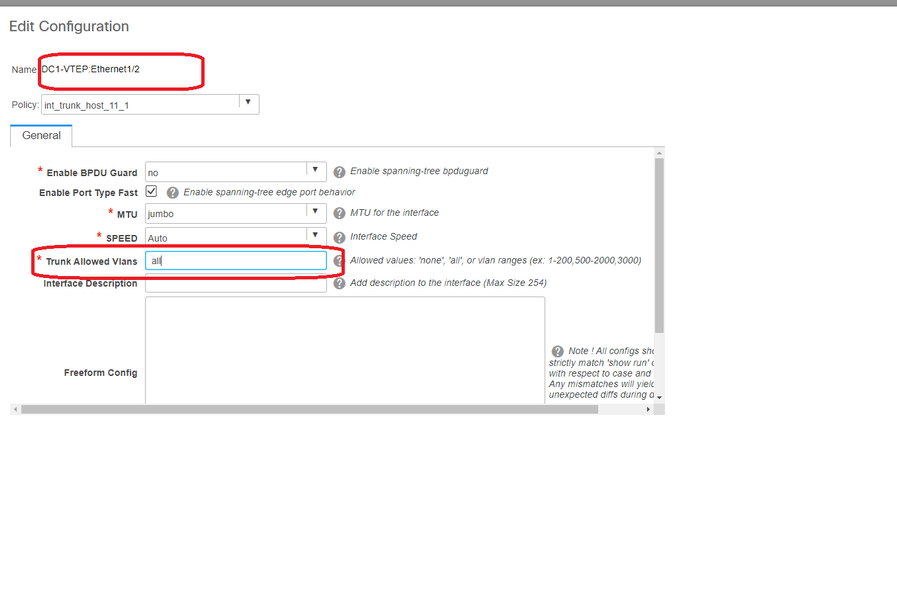
# Select the relevant interface and change the "allowed vlans" from none to "all"(or only the vlans that are needing to be allowed)
Step 12: Freeforms required on Shared border
# Since Shared border switches are the route-servers, it is required to make some changes in terms of the BGP l2vpn evpn neighborships
# inter-site BUM traffic is replicated using Unicast; Means, any BUM traffic in Vlan 144(eg) after it arrives on the BGWs; depending upon which BGW is the Designated forwarder(DF), DF will perform a unicast replication to remote site; This replication is achieved after the BGW receives a type 3 route from the remote BGW; Here, the BGWs are forming l2vpn evpn peering only with shared borders; and Shared borders should not have any layer 2 VNIDs(if created, this will result in blackholing of East/West Traffic). Since layer 2 VNIDs are missing and the route-type 3 is originated by BGWs per VNID, the Shared borders will not honor the BGP update coming in from BGWs; To fix this, Use the "retain route-target all" under the AF l2vpn evpn
# Another point is to make sure that the Shared borders do not change the Next HOP(BGP BY default changes the next hop for eBGP neighborships); Here, the inter site tunnel for unicast traffic from site 1 to 2 and vice versa should be from BGW to BGW(from dc1 to dc2 and vice versa); To achieve this, a route-map has to be created and applied for every l2vpn evpn neighborships from shared border to each BGWs
# For both the above points, a freeform has to be used on shared borders like below
route-map direct
route-map unchanged
  set ip next-hop unchanged
router bgp 65001
  address-family ipv4 unicast
    redistribute direct route-map direct
  address-family l2vpn evpn
    retain route-target all
  neighbor 10.100.100.2
    remote-as 65001
    address-family ipv4 unicast
      next-hop-self
  neighbor 10.10.10.1
    address-family l2vpn evpn
      route-map unchanged out
  neighbor 10.10.10.2
    address-family l2vpn evpn
      route-map unchanged out
  neighbor 10.10.20.1
    address-family l2vpn evpn
      route-map unchanged out
  neighbor 10.10.20.2
    address-family l2vpn evpn
      route-map unchanged out
Step 13: Loopback within tenant VRFs on BGWs
# for North/South traffic from hosts connected within the leaf switches, the BGWs use the Outer SRC IP of the NVE Loopback1 IP address; Shared borders will only by default form the NVE Peering with the Multisite Loopback Ip address of BGWs; so if a vxlan packet comes to the shared border with an outer SRC IP address of the BGW Loopback1, the packet will be dropped due to the SRCTEP Miss; To avoid this, a loopback in tenant-VRF has to be created on every BGW switch and then advertise to the BGP so that the Shared borders receive this update and then form the NVE Peering with the BGW Loopback1 IP address ;
# Initially the NVE Peering will look like below on shared borders
SHARED-BORDER1# sh nve pee
Interface Peer-IP                                 State LearnType Uptime   Router-Mac
--------- --------------------------------------  ----- --------- -------- -----------------
nve1      10.222.222.1                            Up    CP        01:20:09 0200.0ade.de01   # Multisite Loopback 100 IP address of DC1-BGWs
nve1      10.222.222.2                            Up    CP        01:17:43 0200.0ade.de02   # Multisite Loopback 100 IP address of DC2-BGWs

# As shown above, the loopback2 is created from DCNM and is configured in tenant-1 VRF and is given the Tag of 12345 as this is the tag which the route-map uses to match the loopback while making the advertisement
DC1-BGW1# sh run vrf tenant-1

!Command: show running-config vrf tenant-1
!Running configuration last done at: Tue Dec 10 17:21:29 2019
!Time: Tue Dec 10 17:24:53 2019

version 9.3(2) Bios:version 07.66

interface Vlan1445
  vrf member tenant-1

interface loopback2
  vrf member tenant-1
vrf context tenant-1
  vni 1001445
  ip pim rp-address 10.49.3.100 group-list 224.0.0.0/4
  ip pim ssm range 232.0.0.0/8
  rd auto
  address-family ipv4 unicast
    route-target both auto
    route-target both auto mvpn
    route-target both auto evpn
  address-family ipv6 unicast
    route-target both auto
    route-target both auto evpn
router bgp 65000
  vrf tenant-1
    address-family ipv4 unicast
      advertise l2vpn evpn
      redistribute direct route-map fabric-rmap-redist-subnet
      maximum-paths ibgp 2
    address-family ipv6 unicast
      advertise l2vpn evpn
      redistribute direct route-map fabric-rmap-redist-subnet
      maximum-paths ibgp 2


DC1-BGW1# sh route-map fabric-rmap-redist-subnet
route-map fabric-rmap-redist-subnet, permit, sequence 10
  Match clauses:
    tag: 12345
  Set clauses:
# After this step, the NVE peerings will show for all the Loopback1 Ip addresses along with the multisite loopback IP address.
SHARED-BORDER1# sh nve pee
Interface Peer-IP                                 State LearnType Uptime   Router-Mac
--------- --------------------------------------  ----- --------- -------- -----------------
nve1      192.168.20.1                            Up    CP        00:00:01 b08b.cfdc.2fd7
nve1      10.222.222.1                            Up    CP        01:27:44 0200.0ade.de01
nve1      192.168.10.2                            Up    CP        00:01:00 e00e.daa2.f7d9
nve1      10.222.222.2                            Up    CP        01:25:19 0200.0ade.de02
nve1      192.168.10.3                            Up    CP        00:01:43 6cb2.aeee.0187
nve1      192.168.20.3                            Up    CP        00:00:28 005d.7307.8767
# At this stage, the East/West traffic should be forwarded correctly
Step 14: VRFLITE Extensions from Shared borders to the External Routers
# There will be situations when hosts outside the fabric will have to talk to the Hosts within the fabric. In this example, the same is made possible by the shared borders;
# Any host that is living in DC1 or DC2 will be able to talk to external hosts via the shared border switches.
# For that purpose, Shared borders are terminating the VRF Lite; Here in this example eBGP is running from Shared borders to the External routers as shown in the diagram in the beginning.
# For configuring this from DCNM, it is required to add vrf extension attachments. Below steps are to be done for achieving the same.
a) Adding Inter-Fabric links from shared borders to External Routers
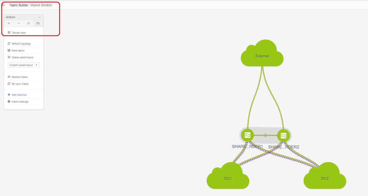
# Select the Fabric builder scope to "shared border" and Change to Tabular View
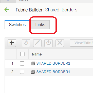
# Select the links and add an "Inter-Fabric" link as shown below
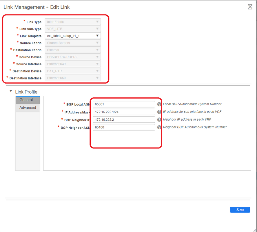
# A VRF LITE sub-type has to be selected from the drop down
# Source Fabric is Shared borders and destination Fabric is External as this is going to be a VRF LITE from SB to External
# Select the relevant interfaces that are going towards the external router
# Provide the IP address and mask and the neighbor IP address
# ASN Will be auto-populated.
# Once this is done, click the Save
# Perform the same for both the Shared borders and for all the external layer 3 connections that are in VRFLITE
b) Adding VRF Extensions
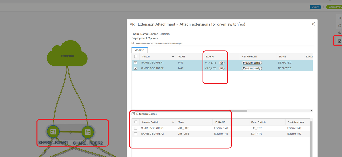
# Go to the Shared Border VRF section
# VRF will be in deployed status; Select the checkbox at the right so that multiple switches can be selected
# Select the Shared borders and the "VRF EXtension attachment" window will open up
# Under "extend", change from "None" to "VRFLITE"
# Do the same for both shared borders
# Once that is done, "Extension Details" will populate the VRF LITE interfaces which were previously given in step a) above.

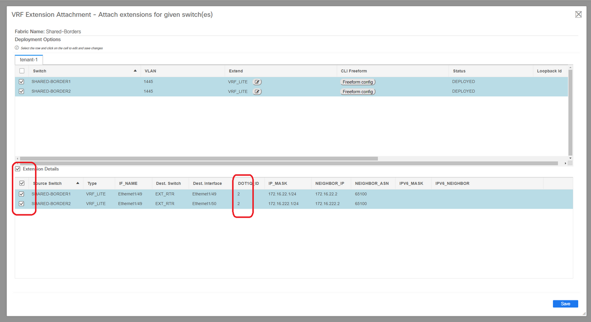
# DOT1Q ID is auto populated to 2
# Other fields are also auto populated
# If IPv6 neighborship has to be established via VRFLITE, step a) should be done for IPv6
# Now click the Save
# Finally, do the "Deploy" at the top right of the web page.
# A successful deploy will result in pushing configurations to the Shared borders which includes setting IP addresses on those sub-interfaces and establishing BGP IPv4 Neighborships with the external routers
# Keep in mind that the external router configurations(setting IP addresses on sub-interfaces and BGP Neighborship statements) are done manually by CLI in this case.
# CLI Verifications can be done by below commands on both the shared borders;
SHARED-BORDER1# sh ip bgp sum vr tenant-1
BGP summary information for VRF tenant-1, address family IPv4 Unicast
BGP router identifier 172.16.22.1, local AS number 65001
BGP table version is 18, IPv4 Unicast config peers 1, capable peers 1
9 network entries and 11 paths using 1320 bytes of memory
BGP attribute entries [9/1476], BGP AS path entries [3/18]
BGP community entries [0/0], BGP clusterlist entries [0/0]

Neighbor        V    AS MsgRcvd MsgSent   TblVer  InQ OutQ Up/Down  State/PfxRcd
172.16.22.2     4 65100      20      20       18    0    0 00:07:59 1

SHARED-BORDER2# sh ip bgp sum vr tenant-1
BGP summary information for VRF tenant-1, address family IPv4 Unicast
BGP router identifier 172.16.222.1, local AS number 65001
BGP table version is 20, IPv4 Unicast config peers 1, capable peers 1
9 network entries and 11 paths using 1320 bytes of memory
BGP attribute entries [9/1476], BGP AS path entries [3/18]
BGP community entries [0/0], BGP clusterlist entries [0/0]

Neighbor        V    AS MsgRcvd MsgSent   TblVer  InQ OutQ Up/Down  State/PfxRcd
172.16.222.2    4 65100      21      21       20    0    0 00:08:02 1
# With all the above Configurations, North/South reachability will be established too as shown below(pings from the External Router to Hosts in Fabric)
EXT_RTR# ping 172.16.144.1                                   # 172.16.144.1 is Host in DC1 Fabric
PING 172.16.144.1 (172.16.144.1): 56 data bytes
64 bytes from 172.16.144.1: icmp_seq=0 ttl=251 time=0.95 ms
64 bytes from 172.16.144.1: icmp_seq=1 ttl=251 time=0.605 ms
64 bytes from 172.16.144.1: icmp_seq=2 ttl=251 time=0.598 ms
64 bytes from 172.16.144.1: icmp_seq=3 ttl=251 time=0.568 ms
64 bytes from 172.16.144.1: icmp_seq=4 ttl=251 time=0.66 ms
^[[A^[[A
--- 172.16.144.1 ping statistics ---
5 packets transmitted, 5 packets received, 0.00% packet loss
round-trip min/avg/max = 0.568/0.676/0.95 ms

EXT_RTR# ping 172.16.144.2                                  # 172.16.144.2 is Host in DC2 Fabric
PING 172.16.144.2 (172.16.144.2): 56 data bytes
64 bytes from 172.16.144.2: icmp_seq=0 ttl=251 time=1.043 ms
64 bytes from 172.16.144.2: icmp_seq=1 ttl=251 time=6.125 ms
64 bytes from 172.16.144.2: icmp_seq=2 ttl=251 time=0.716 ms
64 bytes from 172.16.144.2: icmp_seq=3 ttl=251 time=3.45 ms
64 bytes from 172.16.144.2: icmp_seq=4 ttl=251 time=1.785 ms

--- 172.16.144.2 ping statistics ---
5 packets transmitted, 5 packets received, 0.00% packet loss
round-trip min/avg/max = 0.716/2.623/6.125 ms
# Traceroutes also point to the right devices in the path of the packet
EXT_RTR# traceroute 172.16.144.1
traceroute to 172.16.144.1 (172.16.144.1), 30 hops max, 40 byte packets
 1  SHARED-BORDER1 (172.16.22.1)  0.914 ms  0.805 ms  0.685 ms
 2  DC1-BGW2 (172.17.10.2)  1.155 ms DC1-BGW1 (172.17.10.1)  1.06 ms  0.9 ms
 3  ANYCAST-VLAN144-IP (172.16.144.254) (AS 65000)  0.874 ms  0.712 ms  0.776 ms
 4  DC1-HOST (172.16.144.1) (AS 65000)  0.605 ms  0.578 ms  0.468 ms

EXT_RTR# traceroute 172.16.144.2
traceroute to 172.16.144.2 (172.16.144.2), 30 hops max, 40 byte packets
 1  SHARED-BORDER2 (172.16.222.1)  1.137 ms  0.68 ms  0.66 ms
 2  DC2-BGW2 (172.17.20.2)  1.196 ms DC2-BGW1 (172.17.20.1)  1.193 ms  0.903 ms
 3  ANYCAST-VLAN144-IP (172.16.144.254) (AS 65000)  1.186 ms  0.988 ms  0.966 ms
 4  172.16.144.2 (172.16.144.2) (AS 65000)  0.774 ms  0.563 ms  0.583 ms
EXT_RTR#
Contributed by Cisco Engineers
- Varun JoseTechnical Leader-CX
Contact Cisco
- Open a Support Case

- (Requires a Cisco Service Contract)
 Feedback