Nexus 5500 VM-FEX Configuration Example
Available Languages
Contents
Introduction
This document describes how to configure, operate, and troubleshoot the Virtual Machine Fabric Extender (VM-FEX) feature on Cisco Nexus 5500 switches.
Prerequisites
Requirements
Cisco recommends that you have basic knowledge of these topics.
- Nexus Virtual Port Channel (VPC)
- VMware vSphere
Components Used
The information in this document is based on these hardware and software versions:
- Nexus 5548UP that runs Version 5.2(1)N1(4)
- Unified Computing System (UCS)-C C210 M2 Rack Server with UCS P81E Virtual Interface Card that runs Firmware Version 1.4(2)
- vSphere Version 5.0 (ESXi and vCenter)
The information in this document was created from the devices in a specific lab environment. All of the devices used in this document started with a cleared (default) configuration. If your network is live, make sure that you understand the potential impact of any command or packet capture setup.
VM-FEX Overview
VM-FEX combines virtual and physical networking into a single infrastructure. It allows you to provision, configure, and manage virtual machine network traffic and bare metal network traffic within a unified infrastructure.
The VM-FEX software extends the Cisco fabric extender technology to the virtual machine with these capabilities:
- Each virtual machine includes a dedicated interface on the parent switch.
- All virtual machine traffic is sent directly to the dedicated interface on the switch.
- The standard vSwitch in the hypervisor is eliminated.
VM-FEX is one type of Distributed Virtual Switch (DVS or VDS). The DVS presents an abstraction of a single switch across multiple ESX servers that are part of the same Datacenter container in vCenter. The Virtual Machine (VM) Virtual Network Interface Controller (VNIC) configuration is maintained from a centralized location (Nexus 5000 or UCS in VM-FEX, this document illustrates the Nexus 5000-based VM-FEX).
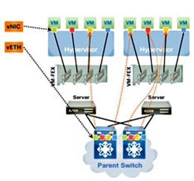
VM-FEX can operate in two modes:
- Pass-through: This is the default mode, in which the VEM is involved in the data path for the VM traffic.
- High-performance: VM traffic is not handled by the VEM but is passed directly to the Network IO Virtualization (NIV) adapter.
In order to use the high-performance mode, it should be requested by the port-profile configuration and should be supported by the VM Operating System and by its virtual adapter. More information about this is provided later in this document.
Definitions
- Virtual Ethernet Module (VEM). Cisco Software module that runs inside the ESX hypervisor and provides VNLink implementation in a single package
- Network IO Virtualization (NIV) uses VNtagging in order to deploy several Virtual Network Links (VN-Link) across the same physical Ethernet channel
- Datacenter Bridging Capability Exchange (DCBX)
- VNIC Interface Control (VIC)
- Virtual NIC (VNIC), which indicates a host endpoint. It can be associated with an active VIF or a standby VIF
- Distributed Virtual Port (DVPort). VNIC is connected to the DVPort in the VEM
- NIV Virtual Interface (VIF), which is indicated at a network endpoint
- Virtual Ethernet (vEth) interface represents VIF at the switch
- Pass-Through Switch (PTS). VEM module installed in the hypervisor
Configure
The topology is a UCS-C server with P81E VIC dual-homed to two Nexus 5548 VPC switches.
Network Diagram
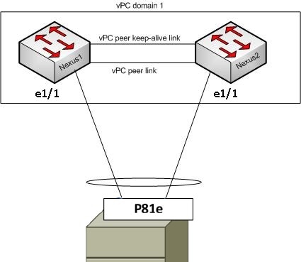
These required components must already be in place:
- The VPC is configured and initialized properly between the two Nexus 5000 switches.
- VMWare vCenter is installed and connected to via a vSphere client.
- ESXi is installed on the UCS-C server and added to vCenter.
Configuration steps are summarized here:
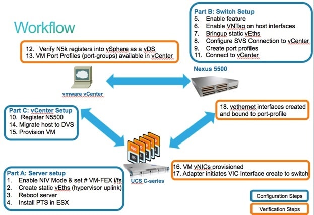
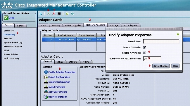
- Enable NIV mode on the server Adapter:
- Connect to the Cisco Integrated Management Controller (CIMC) interface via HTTP and log in with the admin credentials.
- Choose Inventory > Network Adapters > Modify Adapter Properties.
- Enable NIV Mode, set the number of VM FEX interfaces, and save the changes.
- Power off and then power on the server.
After the server comes back online, verify that NIV is enabled: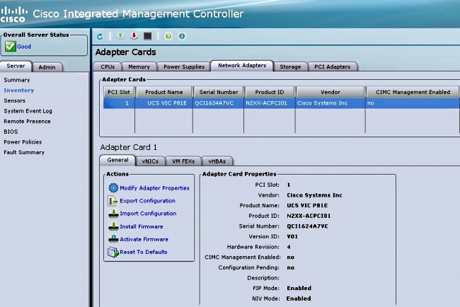
- Connect to the Cisco Integrated Management Controller (CIMC) interface via HTTP and log in with the admin credentials.
- Create two static vEths on the server.
In order to create two VNICs, choose Inventory > Network Adapters > VNICs > Add.
These are the most important fields to be defined:
- VIC Uplink port to be used (P81E has two uplink ports referenced as 0 and 1).
- Channel number: This is a unique channel ID of the VNIC on the adapter. This is referenced in the bind command under the vEth interface on the Nexus 5000. The scope of the channel number is limited to the VNTag physical link. The channel can be thought of as a "virtual link" on the physical link between the switch and the server adapter.
- Port-profile: The list of port-profiles defined on the upstream Nexus 5000 can be selected. A vEth interface is automatically created on the Nexus 5000 if the Nexus 5000 is configured with the vEthernet auto-create command. Note that only the vEthernet port-profile names are passed to the server (port-profile configuration is not). This occurs after the VNTag link connectivity is established and the initial handshake and negotiation steps are performed between the switch and the server adapter.
- Enable Uplink failover: The VNICs failover to the other P81E uplink port if the configured uplink port goes offline.
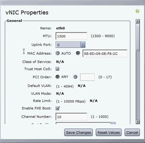
- VIC Uplink port to be used (P81E has two uplink ports referenced as 0 and 1).
- Reboot the server.
- Install the VEM on the ESXi host.
For an example install of the VEM on the ESXi host, refer to Installing or Upgrading the Cisco VEM Software Bundle on an ESX or ESXi Host in Cisco UCS Manager VM-FEX for VMware GUI Configuration Guide, Release 2.1. - Enable the virtualization feature-set and VM-FEX and HTTP features:
(config)# install feature-set virtualization
(config)# feature-set virtualization
(config)# feature vmfex
(config)# feature http-server

(Optional) Allow the Nexus 5000 to auto-create its Vethernet interfaces when the
corresponding vNICs are defined on the server:
(config)# vethernet auto-create - Enable VNTag on host interfaces.
Configure the N5k interface that connects to the servers in VNTAG mode:
(config)# interface Eth 1/1
(config-if)# switchport mode vntag
(config-if)# no shutdown - Bring up static vEths.
On both Nexus 5500 switches, enable the static vEth virtual interfaces that should connect to the two static VNICs enabled on the server VIC.
On the Nexus 5548-A, enter:interface vethernet 1
bind interface eth 1/1 channel 10
no shutdown
On the Nexus 5548-B, enter:interface vethernet 2
bind interface eth 1/1 channel 11
no shutdown
Alternatively, these vEth interfaces can be automatically created with the vethernet auto-create command.
Here is an example.
On each of the two Nexus 5000s, configure:interface Vethernet1
description server_uplink1
bind interface Ethernet101/1/1 channel 11
bind interface Ethernet102/1/1 channel 11
interface Vethernet2
description server_uplink2
bind interface Ethernet101/1/1 channel 12
bind interface Ethernet102/1/1 channel 12 - Configure the SVS connection to vCenter and connect.
On both Nexus 5500 switches, configure:svs connection <name>
protocol vmware-vim
remote ip address <vCenter-IP> vrf <vrf>
dvs-name <custom>
vmware dvs datacenter-name <VC_DC_name>
On the VPC primary switch only, connect to vCenter:svs connection <name>
connect
Sample configuration on VPC primary:
svs connection MyCon
  protocol vmware-vim
  remote ip address 10.2.8.131 port 80 vrf management
  dvs-name MyVMFEX
  vmware dvs datacenter-name MyVC
connect
Here is a sample configuration on VPC secondary:svs connection MyCon
protocol vmware-vim
remote ip address 10.2.8.131 port 80 vrf management
dvs-name MyVMFEX
vmware dvs datacenter-name MyVC - Create port-profiles on the Nexus 5000.
On both Nexus 5500 switches, configure port-profiles for the VM-FEX VNICs. These port-profiles appear as port-groups of the DVS switch in vCenter.
Here is an example:vlan 10,20
port-profile type vethernet VM1
dvs-name all
switchport mode access
switchport access vlan 10
no shutdown
state enabled
port-profile type vethernet VM2
dvs-name all
switchport mode access
switchport access vlan 20
no shutdown
state enabled
VM High-Performance Mode
In order to implement High-Perfomance mode (DirectPath IO) and bypass the hypervisor for the VM traffic, configure the vEthernet port-profile with the high-performance host-netio command. In the case of VPC topologies, the port-profile should be always edited on both VPC peer switches. For example:port-profile type vethernet VM2
high-performance host-netio
In order to have the high-performance mode operational, your VM must have these additional prerequisites:
- The VM virtual adapter should be of type vmxnet3 (check in vCenter: Right-click VM > Edit settings > Network adapter > Adapter type on the right menu).
- The VM must have full memory reservation (in vCenter: Right-click VM > Edit settings > Resources tab > Memory > Slide reservation slider to the rightmost).
- The Operating System that runs on the VM should support this feature.
Here is how you verify High-Performance mode (DirectPath IO) when it is used.
Under the VM Hardware settings, the DirectPath I/O field in the right menu shows as active when VM High-Performance mode is in use and as inactive when the default VM pass-through mode is in use.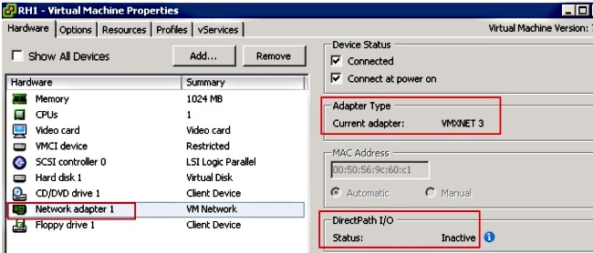
- The VM virtual adapter should be of type vmxnet3 (check in vCenter: Right-click VM > Edit settings > Network adapter > Adapter type on the right menu).
- Register the VPC primary Nexus 5548 in vCenter:
Connect via HTTP to the VPC primary Nexus 5548 and download the extension XML file:
Then, register that extension plug-in in vCenter: choose Plug-ins > Manage Plug-ins > Right click > New Plug-in. - Connect to vCenter. (See Step 8.)
- Verify that the Nexus 5000 registers into vSphere as a vDS:
Verify the creation of a new DVS under vCenter with the name as defined in dvs-name under svs connection on the Nexus 5000: choose Home > Inventory > Networking.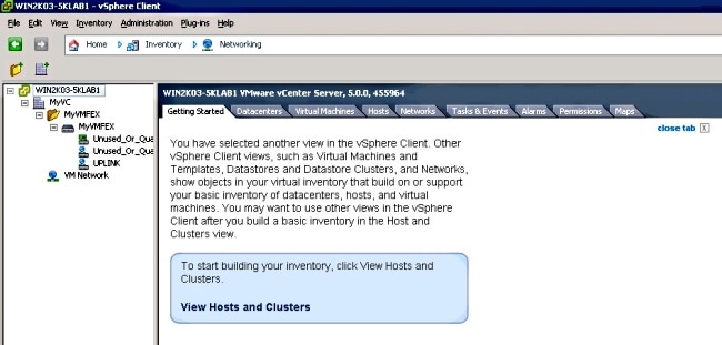
On the Nexus 5000 VPC primary switch, verify that the SVS connection is online with this command:n5k1# show svs connections
Local Info:
-----------
connection MyCon:
ip address: 10.2.8.131
remote port: 80
vrf: management
protocol: vmware-vim https
certificate: default
datacenter name: MyVC
extension key: Cisco_Nexus_1000V_126705946
dvs name: MyVMFEX
DVS uuid: 89 dd 2c 50 b4 81 57 e4-d1 24 f5 28 df e3 d2 70
config status: Enabled
operational status: Connected
sync status: in progress
version: VMware vCenter Server 5.0.0 build-455964
Peer Info:
----------
connection MyCon:
ip address: 10.2.8.131
remote port: 80
vrf: management
protocol: vmware-vim https
extension key: Cisco_Nexus_1000V_126705946
certificate: default
certificate match: TRUE
datacenter name: MyVC
dvs name: MyVMFEX
DVS uuid: -
config status: Disabled
operational status: Disconnected
n5k1# - Ensure that VM port-groups are available in vCenter.
The vEthernet port-profiles defined on the Nexus 5000 should appear in vCenter as port-groups under the DVS in the networking view: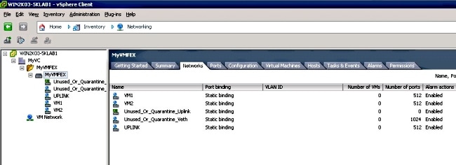
- Migrate ESXi hosts to the DVS.
From VSphere, choose Home > Inventory > Networking, right-click the DVS name, then Add Host in order to add the ESXi hosts to the DVS.
The Adapter-FEX virtual interfaces are the ESXi hosts uplinks. Choose the default uplink port-group (unused_or_quarantine_uplink) for those uplinks ports. - Provision the VM.
Choose a VM-FEX port-group for the network adapter of a VM (right-click VM > Edit Settings > Network Adapter > Network Label in the right menu). - VM VNICs provisioned.
- Adapter initiates VIC Interface create to switch.
When a VM network adapter is mapped to a VM-FEX port-group, a vEthernet interface is dynamically created on the Nexus 5000. The range of dynamically created vEth interfaces starts at 32769.
These interfaces can be checked via these commands:# show interface virtual status
# show interface virtual summary
Verify and Troubleshoot
Use this section in order to verify that your configuration works properly and to troubleshoot any issues you encounter.
- In order to verify that the two static VNICs of the UCS-C server are connected with the VN-Link to the static fixed vEth interfaces on the Nexus 5500, enter this command:
n5k1# show system internal dcbx info interface e1/1

Interface info for if_index: 0x1a001000(Eth1/1)
tx_enabled: TRUE
rx_enabled: TRUE
dcbx_enabled: TRUE
DCX Protocol: CEE
DCX CEE NIV extension: enabled
<output omitted> - In case of active/standby topologies to two dual-homed FEXs, make sure that the vEth interface shows as either active or standby mode on the two Nexus 5000 VPC switches.
Here the mode shows as unknown:
n5k1# show int virtual status
Interface VIF-index   Bound If      Chan  Vlan  Status     Mode     Vntag
-------------------------------------------------------------------------
Veth1     VIF-16      Eth101/1/1      11     1  Up         Active       2
Veth1     None        Eth102/1/1      11     0  Init       Unknown      0
Veth2     None        Eth101/1/1      12     0  Init       Unknown      0
Veth2     None        Eth102/1/1      12     0  Init       Unknown      0
Veth3     VIF-18      Eth101/1/2      11     1  Up         Active       2
Veth3     None        Eth102/1/2      11     0  Init       Unknown      0
Veth4     None        Eth101/1/2      12     0  Init       Unknown      0
Veth4     VIF-19      Eth102/1/2      12     1  Up         Active       3
If you encounter unknown mode, make sure to enable uplink failover mode on the VNIC. Also make sure that the channel number that you specified in the CIMC matches the channel number that is specified in the vEthernet configuration.
The correct output should resemble this:n5k1# show int virtual status
Interface VIF-index Bound If Chan Vlan Status Mode Vntag
-------------------------------------------------------------------------
Veth1 VIF-27 Eth101/1/1 11 1 Up Active 2
Veth1 VIF-35 Eth102/1/1 11 1 Up Standby 2
Veth2 VIF-36 Eth101/1/1 12 1 Up Standby 3
Veth2 VIF-33 Eth102/1/1 12 1 Up Active 3
Veth3 VIF-30 Eth101/1/2 11 1 Up Active 2
Veth3 VIF-21 Eth102/1/2 11 1 Up Standby 2
Veth4 VIF-24 Eth101/1/2 12 1 Up Standby 3
Veth4 VIF-31 Eth102/1/2 12 1 Up Active 3 - vEth interfaces do not appear on the switch.
In the UCS-C server CIMC HTTP menu, verify that:
- NIV is enabled on the adapter.
- A non-zero number of VM-FEX interfaces is configured on the adapter.
- Adapter failover is enabled on the VNIC.
- The UCS-C server was rebooted after the configuration above was made.
- NIV is enabled on the adapter.
- vEth interfaces do not come online.
Check whether VIF_CREATE appears in this command:# show system internal vim info logs interface veth 1
03/28/2014 16:31:47.770137: RCVD VIF CREATE request on If Eth1/32 <<<<<<<
03/28/2014 16:31:53.405004: On Eth1/32 - VIC CREATE sending rsp for msg_id 23889
to completion code SUCCESS
03/28/2014 16:32:35.739252: On Eth1/32 - RCVD VIF ENABLE. VIF-index 698 msg id 23953
VIF_ID: 0, state_valid: n, active
03/28/2014 16:32:35.802019: On Eth1/32 - VIC ENABLE sending rsp for msg_id 23953 to
completion code SUCCESS
03/28/2014 16:32:36.375495: On Eth1/32 - Sent VIC SET, INDEX: 698, msg_id 23051, up,
enabled, active, cos 0VIF_ID: 50 vlan:
1 rate 0xf4240, burst_size 0xf
03/28/2014 16:32:36.379441: On Eth1/32 - RCVD VIC SET resp, INDEX: 698, msg_id 23051,
up, enabled,active, cos 0, completion
code: 100
If VIF_CREATE does not appear or the switch does not properly respond, complete these steps:
- In vCenter, check that the DVS switch has been properly configured with two physical uplinks for the ESX host (right-click DVS switch > Manage Hosts > Select Physical Adapters).
- In vCenter, check that VMNIC has selected the correct network label / port-profile (right-click VM > Edit Settings > click on Network adapter > check Network label).
- In vCenter, check that the DVS switch has been properly configured with two physical uplinks for the ESX host (right-click DVS switch > Manage Hosts > Select Physical Adapters).
- SVS connection to vCenter does not come online.
As shown in Step 12 in the previous section, use this process in order to verify that the Nexus 5000 was connected to vCenter:
- On vCenter, verify that the DVS appears under the networking view.
- On the Nexus 5000 VPC primary, verify that the SVS is connected (use the show svs connection command).
In case the connection is not established, verify that:
- The SVS configuration is identical on both VPC peers.
- VPC is initialized and the roles are established properly.
- The VPC primary switch XML certificate is installed in vCenter.
- The VPC primary switch has "connect" configured under "svs connection" configuration mode.
- The Datacenter name matches the name used on vCenter.
- The correct Virtual Routing and Forwarding (VRF) is configured in the SVS remote command and that the switch has IP connectivity to the vCenter IP address.
If all of these conditions are met but the SVS connection is still not successful, collect this output and contact Cisco Technical Assistance Center (TAC):show msp port-profile vc sync-status
show msp internal errors
show msp internal event-history msgs
show vms internal errors
show vms internal event-history msgs - On vCenter, verify that the DVS appears under the networking view.
- The Nexus 5500 switch is not reachable via HTTP.
Verify that the http-server feature is enabled:n5k1# show feature | i http
http-server 1 disabled
n5k1# conf t
Enter configuration commands, one per line. End with CNTL/Z.
n5k1(config)# feature http-server
n5k1(config)#
Revision History
| Revision | Publish Date | Comments |
|---|---|---|
1.0 |
15-May-2014 |
Initial Release |
Contact Cisco
- Open a Support Case

- (Requires a Cisco Service Contract)


 Feedback