Introduction
This document discusses best practices and checks for online insertion and removal (OIR) of modules in Catalyst 6500 Chassis. These steps are useful to avoid damage to the Catalyst 6500 chassis backplane and modules.
Impact of OIR with damaged module/chassis
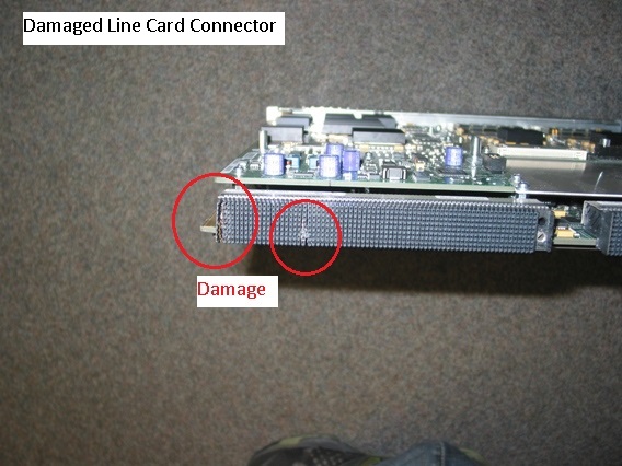
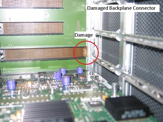
Damaged modules can cause damage to the chassis backplane and visa-versa. Damage on the module backplane connector from improper storage, handling and shipping methods can lead to damage on the chassis backplane. Once chassis backplane has been damaged, that damage will cause damage to subsequent modules that are plugged into that slot. Moving a damaged module from first chassis to second can cause damage on the second chassis.
Example of damaged module connector

Example of damaged chassis backplane connector

Inspection and Insertion Procedure
Module connector inspection
Thoroughly inspect line card backplane interface connector for any damage or wafer misalignment.

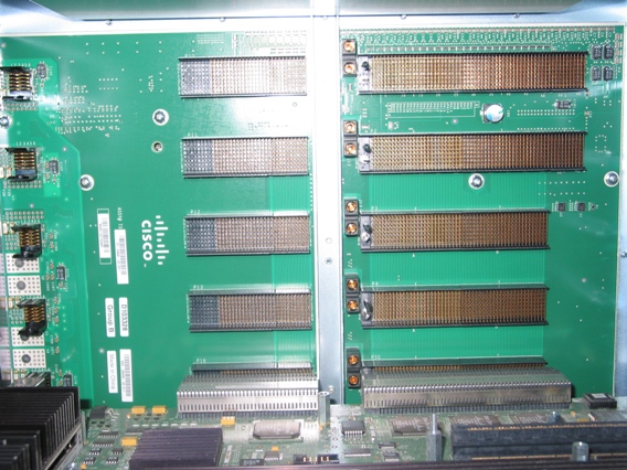
Chassis backplane inspection
1) Thoroughly inspect chassis backplane line card slot to which the line card will be installed.
2) Look for uniformity of backplane connector pins and shields. A light source may be needed to see clearly in a partially populated chassis.

Initial line card insertion into chassis
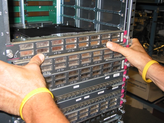
1) Slide module into chassis allowing it to come in contact with system backplane.
2) Using only the pressure of your thumbs pre-insert (seat) the line card into the backplane slot.
3) If the module feels stuck and will not pre-insert there is probably an obstruction that will cause damage. The pre-insertion step should feel smooth and easy.
Note: Line card should slide through card guides on the sides of the chassis with minimal friction.

Final insertion of line card into chassis
1) Using the injector/ejector levers on the edges of the line card fully insert the line card by moving the levers in toward the center of the face plate.
2) Secure the line card into the chassis by tightening the thumb screws on each side of the line card. The face plate of the line card should be flush with the chassis sheet metal.
Note: The injector levers offer mechanical advantage to overcome the insertion force of the mating connectors (> 100 lbs force). If the force applied to the levers feels excessive to insert the line card - pull the card out and re-inspect.

Common Issue During OIR : Switching Bus Stall
When an OIR (Online Insertion and Removal) is performed, a stall signal is generated on the backplane bus to prevent backplane data corruption. Bus stall prevents packets from being transmitted to the backplane, this results in traffic interruption for the duration of the stall.
Bus Stall can be asserted under three different conditions:
- Online Insertion & Removal (OIR)
- Power sequences
- Switching mode change (flow-through, truncated, compact).
Following are examples of online insertion and removal and what happens when bus stall is encountered.
Online Insertion Operation - Normal
1) Prior to card insertion data flows freely over backplane.

2) When line card hits longest pin first (shown in green), power supply is provided to the card but card is not powered yet. Card will be powered only when all pins are in contact.

3) When line card hits second longest pin (shown in red), a stall signal is placed on the backplane to protect the system from data corruption.

4) Bus Stall removed when line card touches the shortest pin (shown as blue pin), bus stall removed and data flows freely.

Online Removal Operation - Normal
1) Bus Stall removed when line card is fully in contact with the shortest pin (shown as blue pin), bus stall is not present and data flows freely.

2) When line card is pulled out, contact with shorted pin lost (shown in blue), a stall signal is placed on the backplane to protect the system from data corruption. Card is powered down.

3) When line card looses contact with the second longest pin first (shown in red), Stall is removed from system and data flow resumes.

4) Card loses contact with all three pins. No impact. System continues with data flowing freely.

Online Insertion - Failing Condition
1) Prior to card insertion data flows freely over backplane.

2) When line card hits longest pin first (shown in green), power supply is provided to the card but card is not powered yet. Card will be powered only when all pins are in contact.

3) When line card hits second longest pin (shown in red), a stall signal is placed on the backplane to protect the system from data corruption.

4) When line card is left in the state where contact is present only with the longest and second longest pins, stall remains asserted and system crashes.

Syslog messages will be generated to show bus stall start and end.
%C6KERRDETECT-SP-4-SWBUSSTALL: The switching bus is experiencing stall for 3 seconds

%C6KERRDETECT-SP-4-SWBUSSTALL_RECOVERED: The switching bus stall is recovered and
data traffic switching continues.
Additional commands for further verification.
6500#remote command switch show nvlog

NVRAM log:

26. 02/28/2013 03:46:22: sp_error_detection_recover_sup:Supervisor detected
non-recoverable Switch BUS stall error
30. 01/28/2014 04:00:43: sp_error_detection_recover_sup:Supervisor detected
non-recoverable Switch BUS stall error


6500#remote command switch show fabric timeout

**** Timeout Error info.*****
Timeout Threshold: 1
Powercycle recovery enabled
Wait time for stall_wait: 3 sec.
Wait time for swbus_check: 3 sec.
Wait time for swbus_recheck: 3 sec.
Wait time for accept: 3 sec.
Wait time for debounce: 5 sec.
Wait time for throttle: 5 sec.
Time when Last stall was removed: 3w6d
I: The error received from the fabric was ignored
A prolonged bus stall can cause the supervisor to crash. You will see logs similar to below when this happens.
*May 28 18:25:34.515 PDT: %C6KERRDETECT-SP-4-SWBUSSTALL: The switching bus is
  experiencing stall for 60 seconds

00:01:58: SP: -------------------------------------------------------------------------
00:01:58: SP: Supervisor Processor crashing due to unrecoverable switching bus stall
00:01:58: SP:  There may be poorly inserted cards on the system
00:01:58: SP:  And there is NO real clue which card is causing the switching bus stall
00:01:58: SP: -------------------------------------------------------------------------

%Software-forced reload
Conclusion
Please follow the best practices discussed above for online insertion and removal of modules. Inspect the modules / chassis and if damaged, please contact Cisco TAC to see if RMA is necessary. Do not insert a line card that is found to have damage.
