Configure RSPAN on CBS 220 Series Switches
Available Languages
Objective
This article provides instructions on how you can configure Remote Switch Port Analyzer (RSPAN) on your CBS220 series switches.
Introduction
Switch Port Analyzer (SPAN), or sometimes called port mirroring or port monitoring, chooses network traffic for analysis by a network analyzer. The network analyzer can be a Cisco SwitchProbe device or other Remote Monitoring (RMON) probe.
The switch creates a copy of the traffic activity on a given port or VLAN and sends this copy to the port that is connected to the analyzer network/device. You can apply this feature to monitor the traffic activity on a given port and check for intruders that want to break into your network, which provides security to your network and its resources. A network analyzer connected to the monitoring port processes the data packets for diagnosing, debugging, and performance monitoring.
Remote Switch Port Analyzer (RSPAN) is an extension of SPAN. RSPAN extends SPAN by enabling monitoring of multiple switches across your network and allowing the analyzer port to be defined on a remote switch. This means that you can centralize your network capture devices.
RSPAN works by mirroring the traffic from the source ports of an RSPAN session onto a VLAN that is dedicated for the RSPAN session. This VLAN is then trunked to other switches, allowing the RSPAN session traffic to be transported across multiple switches. On the switch that contains the destination port for the session, traffic from the RSPAN session VLAN is simply mirrored out the destination port.
RSPAN Traffic Flow
- The traffic for each RSPAN session is carried over a user-specified RSPAN VLAN that is dedicated for that RSPAN session in all participating switches.
- The traffic from the source interfaces on the start device is copied to the RSPAN VLAN through a reflector port. This is a physical port that has to be set. It is used exclusively to build an RSPAN session.
- This reflector port is the mechanism that copies packets to an RSPAN VLAN. It forwards only the traffic from the RSPAN source session with which it is affiliated. Any device connected to a port set as a reflector port loses connectivity until the RSPAN source session is disabled.
- RSPAN traffic is then forwarded over trunk ports on the intermediate devices to the destination session on the final switch.
- The destination switch monitors the RSPAN VLAN and copies it to a destination port.
RSPAN Port Membership Rules
- On all switches - Membership in RSPAN VLAN can be tagged only.
- Start Switch
- SPAN source interfaces cannot be members of RSPAN VLAN.
- Reflector port cannot be a member of this VLAN.
- It is recommended that the remote VLAN does not have any memberships.
- Intermediate Switch
- It is recommended to remove RSPAN membership from all ports not used for passing mirrored traffic.
- Usually, an RSPAN remote VLAN contains two ports.
- Final Switch
- For mirrored traffic, source ports must be members of RSPAN VLAN.
- It is recommended to remove RSPAN membership from all other ports, including the destination interface.
Applicable Devices | Software Version
- CBS220 series (Data Sheet) | 2.0.0.17 (Download latest)
Table of Contents
- Configure RSPAN VLAN on the Switch
- Configure Session Sources on a Start Switch
- Configure Session Destinations on a Start Switch
- Configure Session Sources on a Final Switch
- Configure Session Destinations on a Final Switch
Configure RSPAN on the Network
Configure RSPAN VLAN on the Switch
The RSPAN VLAN carries SPAN traffic between RSPAN source and destination sessions. It has these special characteristics:
- All traffic in the RSPAN VLAN is always flooded.
- No Media Access Control (MAC) address learning occurs on the RSPAN VLAN.
- RSPAN VLAN traffic only flows on trunk ports.
- STP can run on RSPAN VLAN trunks but not on SPAN destination ports.
- RSPAN VLANs must be configured on both Start and Final switches in VLAN configuration mode by using the remote-span VLAN configuration mode command, or follow the instructions below:
Step 1
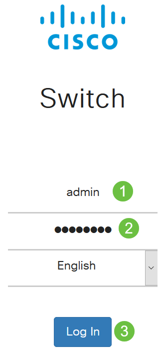
Log in to the web user-interface (UI) of the Start Switch.
Step 2
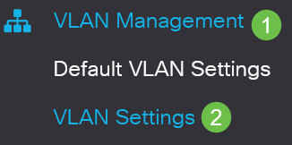
Choose VLAN Management > VLAN Settings.
Step 3
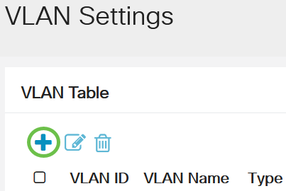
Click Add.
Step 4
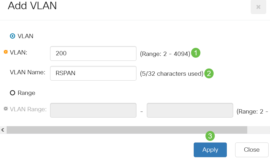
Enter the RSPAN VLAN number in the VLAN field, a VLAN Name, and click Apply.
To learn more about configuring VLAN, check out the article on Configure VLAN on Cisco Business 220 Series Switches.
Step 5
(Optional) Click Save to update the running configuration file.

Step 6
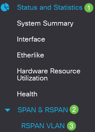
Choose Status and Statistics > SPAN & RSPAN > RSPAN VLAN.
Step 7
Choose a VLAN ID from the RSPAN VLAN drop-down list. This VLAN should be exclusively used for RSPAN.
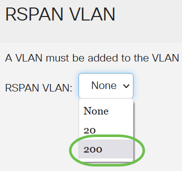
In this example, VLAN 200 is chosen.
Step 8
Click Apply.

Step 9
(Optional) Click Save to update the running configuration file.

Step 10
In the Final Switch, repeat steps 1 to 9 to configure RSPAN VLAN.
You have now configured the VLAN that is dedicated to the RSPAN session on both Start and Final Switches.
Configure Session Sources on a Start Switch
In a single local SPAN or RSPAN session source, you can monitor the port traffic, such as received (Rx), transmitted (Tx), or bidirectional (both). The switch supports any number of source ports (up to the maximum number of available ports on the switch) and any number of source VLANs. To configure the source ports to be mirrored, follow these steps:
Step 1
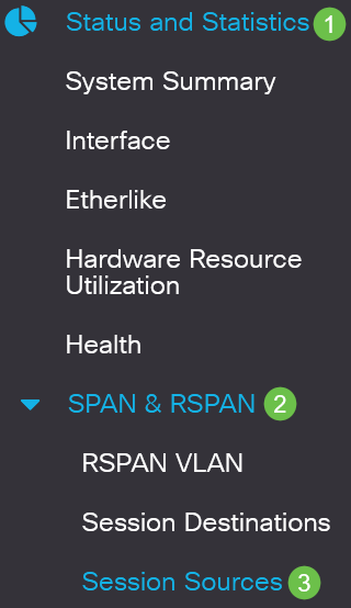
Choose Status and Statistics > SPAN & RSPAN > Session Sources.
Step 2
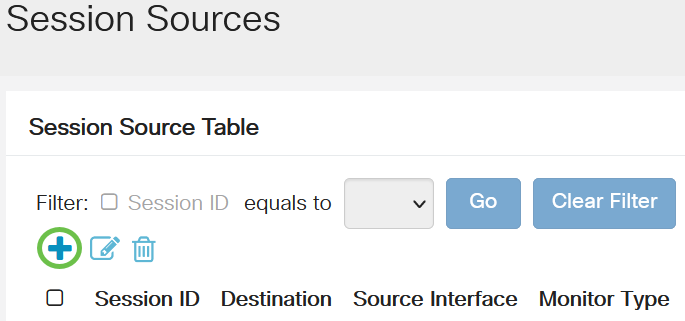
Click Add.
Step 3
Choose the session number from the Session ID drop-down list. Session ID must be consistent per RSPAN session.
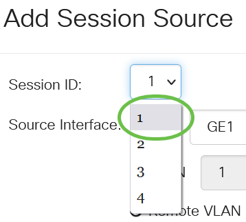
In this example, Session 1 is chosen.
Step 4
Click the radio button for the desired Source Interface from the drop-down menu.
The Source Interface cannot be the same as the Destination Port.
The options are:
- Port - You can choose the desired port to set as the source port from the Port drop-down list.
- VLAN - You can choose the desired VLAN to monitor from the VLAN drop-down list. A VLAN helps a group of hosts to communicate as if they are on the same physical network, regardless of their location. If this option is chosen, it could not be edited.
- Remote VLAN - This will display the defined RSPAN VLAN. If this option is chosen, it could not be edited.
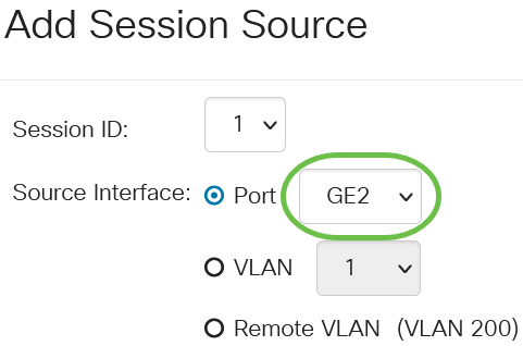
In this example, port GE2 is chosen.
Step 5
(Optional) If Port is selected in Step 4, click the desired Monitor Type radio button for the type of traffic to monitor.
The options are:
- Rx and Tx - This option allows port mirroring of incoming and outgoing packets. This option is chosen by default.
- Rx - This option allows port mirroring of incoming packets.
- Tx - This option allows port mirroring of outgoing packets.
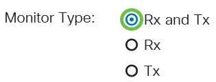
In this example, Rx and Tx is chosen.
Step 6
Click Apply.
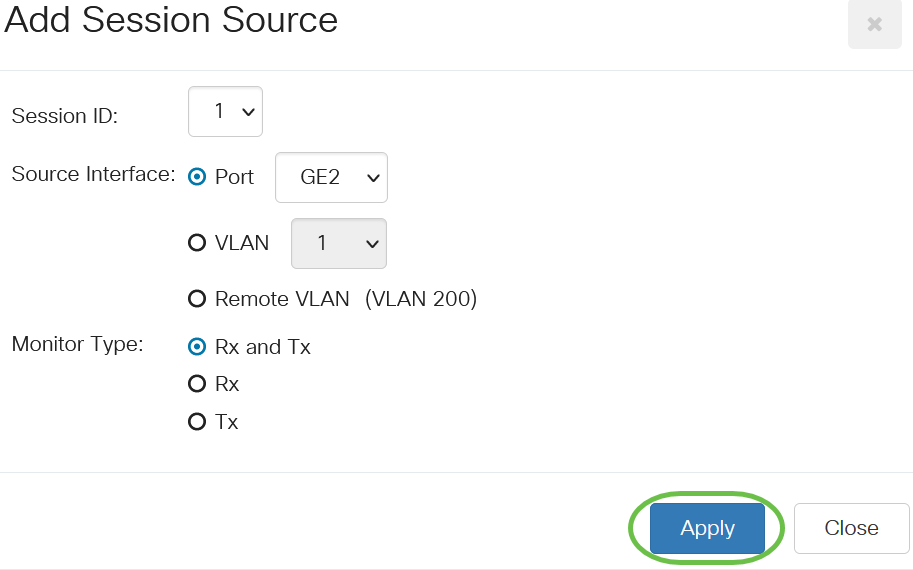
Step 7
(Optional) Click Save to update the running configuration file.

You have now configured the session source on your Start Switch.
Configure Session Destinations on a Start Switch
A monitoring session consists of one or more source ports and a single destination port. A destination port must be configured on the start and final devices. On the start device, this is the reflector port. On the final device, it is the analyzer port. To add a destination port, follow these steps:
Step 1
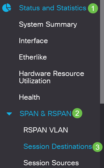
Choose Status and Statistics > SPAN & RSPAN > Session Destinations.
Step 2
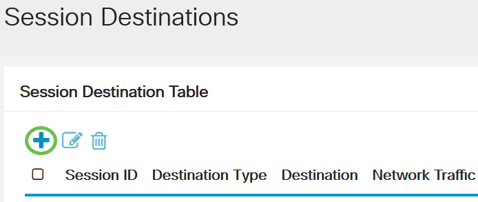
Click Add.
Step 3
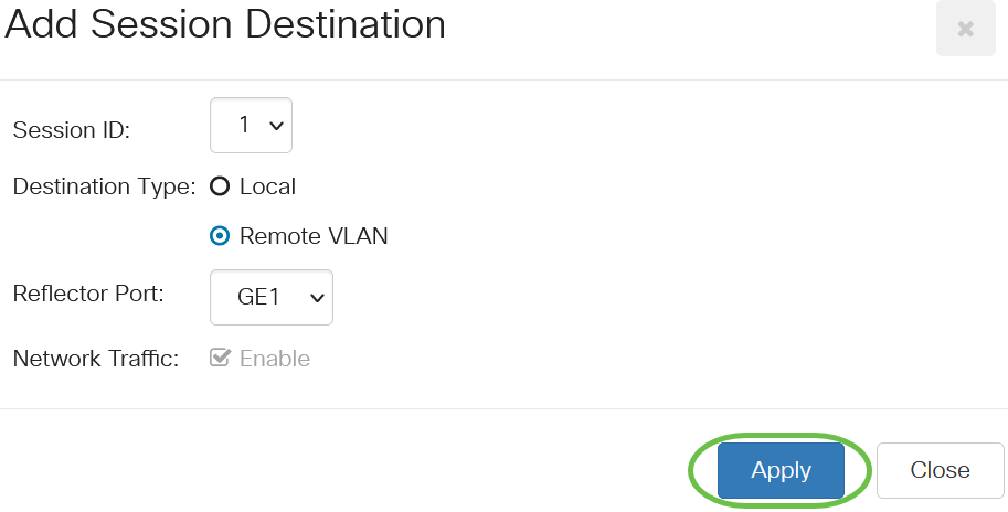
Choose the session number from the Session ID drop-down list. It must be the same as the chosen ID from the configured session source.

In this example, Session 1 is chosen.
Step 4
Click the Remote VLAN radio button from the Destination Type field.

The Destination Interface cannot be the same as the Source Port. If Remote VLAN is chosen, the Network Traffic is automatically enabled.
Step 5
In the Reflector Port field, choose the desired option from the drop-down list.

Step 6
Click Apply.
Step 7
(Optional) Click Save to update the running configuration file.

You have now configured the session destinations on your Start Switch.
Configure Session Sources on a Final Switch
Step 1
Choose Status and Statistics > SPAN & RSPAN > Session Sources.

Step 2
Click Add.

Step 3
(Optional) Choose the session number from the Session ID drop-down list. Session ID must be consistent per session.

In this example, Session 1 is chosen.
Step 4
Click the Remote VLAN radio button in the Source Interface field.
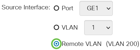
The Monitor Type of the Remote VLAN will be automatically configured.
Step 5
Click Apply then click Close.

Step 6
(Optional) Click Save to update the running configuration file.

You have now configured the session sources on your Final Switch.
Configure Session Destinations on a Final Switch
Step 1
Choose Status and Statistics > SPAN & RSPAN > Session Destinations.

Step 2
Click Add.

Step 3
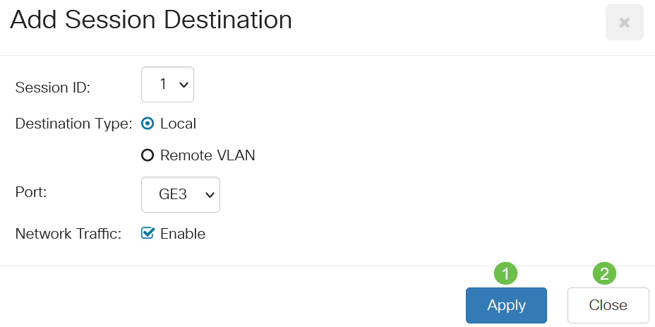
Choose the session number from the Session ID drop-down list. It must be the same as the chosen ID from the configured session source.

In this example, Session 1 is chosen.
Step 4
Click Local radio button in the Destination Type field.

Step 5
In the Port field, choose the desired option from drop-down list.

In this example, port GE3 is chosen.
Step 6
(Optional) In the Network Traffic field, check the Enable check box to enable network traffic.

Step 7
Click Apply then click Close.
Step 8
(Optional) Click Save to update the running configuration file.

You have now configured the session destinations on your Final Switch.
Conclusion
You did it! You have successfully configured the RSPAN session on your CBS220 switches.
Contact Cisco
- Open a Support Case

- (Requires a Cisco Service Contract)
 Feedback