Configure STP on a CBS 220 Series Switch
Available Languages
Objective
This article aims to show you how to configure Spanning Tree Protocol (STP) on a Cisco Business 220 series switch.
Introduction
STP protects Layer 2 broadcast domains from broadcast storms. It sets the links to standby mode to prevent network loops. Network Loops occur when there are alternate routes between hosts. These loops cause Layer 2 switches to forward traffic across the network infinitely, reducing network efficiency. STP provides a unique path between endpoints on a network. These paths eliminate the possibility of network loops. STP is typically configured when there are redundant links to a host to prevent network loop.
Applicable Devices | Software Version
- CBS220 series (Data Sheet) | 2.0.0.17
Configure Spanning Tree Protocol
Step 1
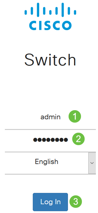
Log in to the web user interface (UI) of CBS220 switch.

Step 2
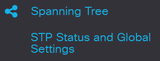
Choose Spanning Tree > STP Status and Global Settings.

Step 3
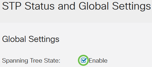
Check the Spanning Tree State check box to enable spanning tree.

Step 4
Choose the STP Operation Mode.
- Classic STP - Provides a single path between any two endpoints, eliminating and preventing networking loops.
- Rapid STP - Detects network topologies to provide faster convergence of the spanning tree. This option is enabled by default.
- Multiple STP - It is based on RSTP. It detects Layer 2 loops, and attempts to mitigate them by preventing the involved port from transmitting traffic.

Step 5
(Optional) Select how Bridge Protocol Data Unit (BPDU) packets are managed when STP is disabled. BPDUs are used to transmit spanning tree information. Choose the BPDU Handling mode.
- Filtering - filters BPDU packets when spanning tree is disabled on an interface. Only a few BPDU packets are exchanged among the switches.
- Flooding - Floods BPDU packets when spanning tree is disabled on an interface. All the BPDU packets are exchanged among all the switches.

Step 6
Choose the Path Cost Default Values. This selects the method used to assign default path costs to the STP ports. The default path cost assigned to an interface varies according to the selected method.
- Short - Specifies the range 1 through 65,535 for port path costs.
- Long - Specifies the range 1 through 200,000,000 for port path costs.

Step 7
Under the Bridge Settings area, enter the bridge priority value in the Priority field. After exchanging BPDUs, the device with the lowest priority becomes the Root Bridge. In case all bridges use the same priority, then their MAC addresses are used to determine the Root Bridge.

The bridge priority value is provided in increments of 4096. For example, 4096, 8192, 12288, and so on. The default value is 32768.
Step 8
In the Hello Time field, set the interval (in seconds) that a Root Bridge waits between configuration messages.

Step 9
Enter the Max Age value in the Max Age field. It is the interval, in seconds, that the device can wait without receiving a configuration message, before attempting to redefine its own configuration.

Step 10
Enter the Forward Delay value in the Forward Delay field. This is the interval that a bridge remains in a learning state before forwarding packets.

Step 11
Click Apply.

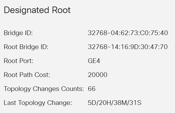
The Designated Root area displays the following:
- Bridge ID - The bridge priority is bound with the MAC address of the switch.
- Root Bridge ID - The Root Bridge priority is bound with the MAC address of the switch.
- Root Port - The port that has the lowest cost path from this bridge to the Root Bridge.
- Root Path Cost - The cost of the path from this bridge to the root.
- Topology Changes Counts - The total number of STP topology changes that have occurred.
- Last Topology Change - The time interval that has elapsed since the last topology change occurred. It is displayed in days/hours/minutes/seconds.

Conclusion
You did it! You have now successfully configured STP on your CBS220 switch.
For more configurations, refer to the Cisco Business 220 Series Switches Administration Guide.
Contact Cisco
- Open a Support Case

- (Requires a Cisco Service Contract)
 Feedback