Onboard Packet Capture in Catalyst 1200 and 1300 Switches
Available Languages
Objective
The objective of this article is to go over the new onboard packet capture (OPC) feature in Catalyst 1200 and 1300 switches on firmware version 4.1.3.36. In this firmware, the OPC can only be configured using the command line interface (CLI).
Applicable Devices | Software Version
- Catalyst 1200 Switches | 4.1.3.36
- Catalyst 1300 Switches | 4.1.3.36
Introduction
In firmware version 4.1.3.36 of Catalyst 1200 and 1300 switches, a new feature called the onboard packet feature (OPC) has been introduced. When enabled, OPC will allocate up to a maximum of 20MB of memory for capturing packet data. This feature requires the configuration of a capture point that defines the behavior of an OPC instance. The capture point is used to define all the settings associated with an OPC instance. The OPC feature enhances troubleshooting capabilities on the device.
In this firmware, OPC can only be configured using the CLI. Capture points are configured in privileged EXEC mode, and they can neither be saved to the configuration files of the switch nor are the settings saved after a reboot of the switch.
A maximum of 4 capture points can be configured on a switch, however only one capture point may be active at a time. Packet capture is supported for the control plane (CPU) interface. The data captured in memory can be saved to either the onboard flash if there is free space, or to an attached USB device like a USB flash drive. As OPC may consume considerable CPU resources, it is recommended to use it only as needed.
Table of Contents
- Commands for Configuring Capture Points
- Buffer Settings
- Source Interface Settings
- Capture Filter Settings
- Starting and Stopping the Capture
- Saving the Packet Capture Data
Commands for Configuring Capture Points
Step 1
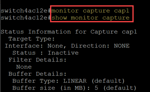
A capture point can be created by using the command monitor capture {capture-name}.
switch# monitor capture cap1
In the above example, a capture point named cap1 has been created.
Step 2
To view the details of a configured capture point, type the command show monitor capture {capture-name}.
switch# show monitor capture cap1
You can see all the currently configured capture points by using the show monitor capture command without specifying a capture name.
Step 3
To delete a capture point, use the command no monitor capture {capture-name}.
switch# no monitor capture cap1

Buffer Settings
You can customize the buffer settings used in a capture point, specifically the size of the buffer and the buffer mode.
- The minimum buffer size is 1MB and the maximum is 20MB.
- If no buffer size is specified, then a default size of 5MB will be used.
- A maximum of 20MB of memory can be allocated across all capture points. You can have a single capture point that is allocated 20MB, but you cannot have four capture points each configured to use 20MB. The total 20MB is split across all the configured capture points.
- There are two buffer modes: linear and circular.
- Linear mode is the default mode. With linear mode, an active packet capture will collect data until the configured buffer is full and then the capture will stop. Additionally, you will not be able restart a packet capture when using linear logging and if the buffer is already full. In this instance, you will need to clear the buffer first.
- With circular buffer mode, once the buffer is full it will then overwrite the data previously captured using First In First Out (FIFO). A capture using circular buffer mode will need to be manually stopped.
Step 1
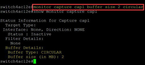
The command to manually configure the buffer settings is monitor capture {capture-name} buffer {circular [size buffer-size] | size buffer-size}.
switch# monitor capture cap1 buffer size 2 circular
In this example, a buffer size of 2MB is configured for cap1 capture point and the buffer mode is circular.
Step 2
Using the command no monitor capture {capture-name} buffer {circular [size buffer-size] | size buffer-size} will change the buffer mode back to the default linear mode.
switch# no monitor capture cap1 buffer size 2 circular
Using the “no” command without the [circular] and [size] options will set the buffer mode and size to their default setting which is linear mode and 5MB buffer size.
Step 3
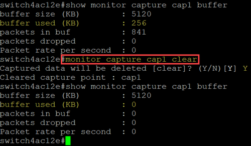
To empty a buffer, use the command monitor capture {capture-name} clear.
switch# monitor capture cap1 clear
In this example, the buffer in cap1 was using 256KB. After issuing the clear command, the buffer is now at 0KB.
Source Interface Settings
Once a capture point has been created, the source interface for the capture needs to be set. The source interface setting is mandatory to start a capture.
- Currently the control-plane is the only source type supported.
- To set the direction, choose from the following options: in, out, or both.
- In - captures inbound packets to the switch.
- Out - captures outbound packets from the switch.
- Both - captures inbound and outbound packets.
Step 1
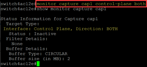
Use the command monitor capture {capture-name} control-plane {in | out | both} to configure the source interface setting.
switch# monitor capture cap1 control-plane both
Step 2
Use the no monitor capture {capture-name} control-plane {in | out | both} command to remove the source interface setting.
switch# no monitor capture cap1 control-plane both
Capture Filter Settings
Capture filter is a mandatory setting that must be configured for a packet capture. Currently, filter operation is not supported in the firmware 4.1.3.36. and all packets on the source interface (which is the control plane) will be captured. However, you will still need to configure this parameter using the “any” option.
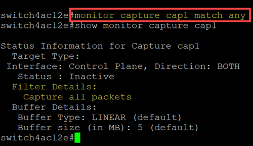
Use the command monitor capture {capture-name} match any to configure the capture filter setting.
switch# monitor capture cap1 match any
In this example, the capture point cap1 has been configured to match any packets.
Starting and Stopping the Capture
Before starting a capture make sure to:
- Set the source interface and capture filter.
- It is recommended to check the CPU utilization before start.
It is important to note that only a single capture session can be active at one time. If a capture is restarted after it was stopped, the new packets will be appended in the buffer. However, a capture cannot be restarted if the buffer is full, and the mode is set to linear.
Step 1
To start the capture, use the command monitor capture {capture-name} start.
switch# monitor capture cap1 start
Step 2
To stop a capture, use the command monitor capture {capture-name} stop.
switch# monitor capture cap1 stop

Saving the Packet Capture Data
Once a packet capture is completed, the data in the buffer (which is RAM) will need to be saved. There are two instances when the data is saved:
- When triggered by a user using a CLI command
- Automatically if a fatal error occurs.
A user can save the packet capture to either the onboard flash of the switch, if there is space for it, or to an attached USB device like a flash drive. If a fatal error occurs during a packet capture, the data will automatically be saved to the main directory of the flash.
To export the packet capture, use the command to monitor capture {capture-name} export {destination/filename}
switch# monitor capture cap1 export flash: cap1.pcap
switch# monitor capture cap1 export usb: cap1.pcap

If a capture is saved to the flash, it can be copied to a USB flash drive via the CLI command copy {filename} usb:/
C1200 and C1300 switches support USB drives formatted in FAT and FAT32. If you do not have a FAT or FAT32 USB drive, you will need to copy the file off the switch using Trivial File Transfer Protocol (TFTP).
To copy a file of the switch using TFTP:
- Configure a TFTP server (using TFTPD64 or some other service)
- Use the following command from the switch CLI:
switch#copy flash://{pcap file name} tftp://{tftp server ip}/{pcap file name}
Alternatively, to copy the file to Secure Copy Protocol (SCP) server, use the command:
switch# copy flash://{pcap file name} scp://{scp server ip}/{scp file name}
Conclusion
Now you know all about the onboard packet capture feature in the Catalyst 1200 and 1300 switches and the CLI commands to configure the settings.
Revision History
| Revision | Publish Date | Comments |
|---|---|---|
1.0 |
25-Jun-2024 |
Initial Release |
Contact Cisco
- Open a Support Case

- (Requires a Cisco Service Contract)
 Feedback