Configure Basic Wireless Settings on the RV340W Router
Available Languages
Objective
Wireless networking operates by sending information over radio waves, which can be more vulnerable to intruders than a wired network. You can keep your network more secure by configuring the basic wireless settings of the router. The RV340W router has provided four default Service Set Identifiers (SSIDs) that use the same default passwords which can be customized to increase network security.
This article aims to show you how to configure the basic wireless settings of the RV340W Router.
Applicable Devices
- RV340W
Software Version
- 1.0.01.16
Configure Basic Wireless Settings
Configure 2.4 GHz
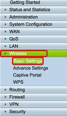
Step 1. Log in to the router web-based utility and choose Wireless > Basic Settings > 2.4G.
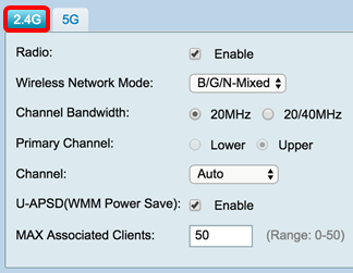
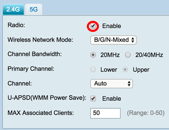
Step 2. Ensure that the Enable Radio check box is checked to activate wireless networks. This option is checked by default.
Note: The RV340W is equipped with a physical switch for the wireless radio. It must be in the ON position to be able to manipulate this page.
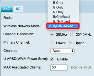
Step 3. In the Wireless Network Modedrop-down list, choose a wireless network mode.
The options are:
- B/G/N-Mixed — Allows Wireless-B, Wireless-G, and Wireless-N devices to connect to the network. Choosing B/G/N-Mixed will allow a range of devices with different wireless standards to connect to your wireless network.
- B Only — Allows devices that support only the 802.11b standard to connect to the network. Wireless-B has a maximum raw data rate of 11 Mbps. Devices on this wireless band often experience interference from other products operating in the 2.4 GHz frequency range.
- G Only — Allows devices that support only the Wireless-G standard to connect to the network. The 802.11g standard operates at a maximum rate of 54 Mbps at the 2.4 GHz frequency range.
- N Only — Allows devices that support only the Wireless-N standard to connect to the network. The 802.11n standard operates in both the 2.4 GHz and 5 GHz frequency band.
- B/G-Mixed — Allows devices that support the 802.11b and 802.11g standards to connect to the network.
- G/N-Mixed — Allows devices that support the 802.11g and 802.11n standards to connect to the network.
Note: If your wireless client devices operate on a specific wireless network mode, it is best to choose that network mode. For example, if your wireless devices only support the 802.11N standard, then you should choose N Only from the Wireless Network Mode drop-down list. Subsequently, if you have a range of devices that operate on different wireless network modes, it is best to choose one of the mixed network mode options. In this example, B/G/N-Mixed is chosen.
Step 4. If you selected B/G/N-Mixed, N Only, or G/N-Mixed in Step 3, choose the wireless bandwidth on your network. Otherwise, skip to Step 6.
- 20MHz — Works with the B/G/N-Mixed, G/N-Mixed, and N Only network mode, but may be prone to lower throughput.
- 20/40MHz — Lets the router switch between 20MHz and 40MHz automatically between 20 and 40MHz. It has better throughput but not as stable as 20MHz.
Note: In this example, 20/40MHz is chosen.

Step 5. (Optional) Choose the appropriate radio button to set a channel as primary. The primary channel is used for devices that only support 20/40 MHz channels.
Note: For this example, Lower is chosen. The radio buttons may be grayed out if Channel is set to Auto. To change this, skip to Step 6.

Step 6. In the Channel drop-down list, choose the channel.
Note: Choosing Auto allows the router to automatically change wireless frequency to the least congested channel. If there are numerous devices operating on the 2.4 GHz frequency, it is recommended to choose Channel 1 which operates at 2.412 GHz or Channel 11 which operates at 2.462 GHz. Most consumer grade access points default to Channel 6. By choosing Channel 1 or Channel 11, you eliminate potential interference among your devices.
The channel varies slightly in frequency range and speed. If you choose the lower frequency, you will have a longer wireless range but slower speed. If you have a higher frequency, you will have shorter wireless range but faster speed. In this example, the wireless channel is left at Auto, which is also the default setting.
In this example, Channel 6 is chosen.

Step 7. (Optional) Check the Enable check box in the U-APSD (WMM Power Save) area to enable the Unscheduled Automatic Power Save Delivery (U-APSD) feature. U-APSD is a power-saving scheme optimized for real-time applications such as utilizing Voice over Internet Protocol (VoIP) and transferring full-duplex data over WLAN. By classifying outgoing IP Traffic as voice data, these types of application can increase battery life and minimize transmit delays.
Note: In this example, U-APSD (WMM Power Save) is disabled. However, this option is enabled by default.

Step 8. Limit the number of clients allowed to be associated with the radio frequency by entering a value ranging from 0-50 in the MAX Associated Clients field. The default is 50.
Note: In this example, the maximum amount of associated clients is 15.

Step 9. Click Apply.

You should now have successfully configured the basic wireless settings for the 2.4 GHz band on the RV340W Router.
Configure 5 GHz band
Step 1. Click the 5G tab.

Step 2. Ensure that the Enable Radio check box is checked to activate wireless networks. This option is checked by default.

Step 3. In the Wireless Network Mode drop-down list, choose a wireless network mode. The options are:
- A Only — Operates between 5.725 GHz to 5.850 GHz and supports up to 54 Mbps. Choose this option if you have only Wireless-A devices in your network.
- N/AC-Mixed — Choose this option if you have a mix of Wireless-N and Wireless-AC devices in your network.
- A/N/AC-Mixed — Choose this option if you have a mix of Wireless-A, Wireless-N, and Wireless-AC devices in your network. This is the default 5G setting for the RV340W.
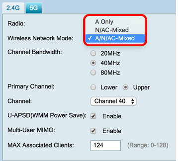
Step 4. Choose the wireless band under Channel Bandwidth. The options are:
- 20MHz — Works with the B/G/N-Mixed, G/N-Mixed, and N-Only network mode, but may be prone to lower throughput.
- 40MHz — It has better throughput but not as stable as 20MHz. Choosing this option allows you to select a primary channel.
- 80MHz — This is the default setting. It is for optimum throughput for Wireless-AC mode.
Note: In this example, 40MHz is chosen.

Step 5. (Optional) Choose the appropriate radio button to set a channel as primary. The primary channel is used for devices that only support 20/40 MHz channels.
Note: For this example, Upper is chosen. The radio buttons may be greyed out if Channel is set to Auto. To change this, skip to Step 6.

Step 6. In the Wireless Channel drop-down list, choose the wireless channel. Depending on your device, the available channels will vary.
Note: In this example, Channel 40 is chosen.

Step 7. (Optional) Check the Enable check box in the U-APSD (WMM Power Save) area to enable the Unscheduled Automatic Power Save Delivery (U-APSD) feature. U-APSD is a power-saving scheme optimized for real-time applications such as utilizing Voice over Internet Protocol (VoIP) and transferring full-duplex data over WLAN. By classifying outgoing IP Traffic as voice data, these types of application can increase battery life and minimize transmit delays.
Note: In this example, U-APSD (WMM Power Save) is disabled. However, this option is enabled by default.

Step 8. (Optional) Check the Enable Multi-User MIMO check box to enable concurrent downstream communication to multiple wireless devices for more efficient use of the spectrum. This is enabled by default. The RV340W supports Multi-User Multiple Input, Multiple Output (MU-MIMO).

Step 9. Limit the number of clients allowed to be associated with the radio frequency by entering a value ranging from 0-128 in the MAX Associated Clients field. The default is 124.
Note: In this example, the maximum amount of associated clients is 50.
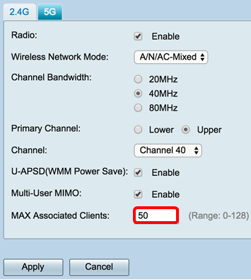
Step 10. Click Apply.
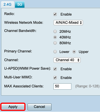
You should now have successfully configured the basic wireless settings for the 5 GHz band.
Change the Wireless Network Name or SSID
Step 1. In the Wireless Table area, check the boxes corresponding to the SSIDs you want to configure. You can edit multiple SSIDs at the same time.
Note: In this example, only the ciscosb1 SSID is edited.

Step 2. Click Edit to modify the SSID.

Note: You will be taken to the Add/Edit Wireless SSID Settings page.

Step 3. Change the default name of your SSID in the SSID Name field. The default SSID name is ciscosb1.
Note: In this example, the SSID Name is changed to Network_Find.

Step 4. Enable the SSID by checking the Enable check box. The default setting of the first SSID is disabled.

Step 5. Choose a radio frequency from which the SSID will broadcast itself from the Actively applied to Radio drop-down list. The options are:
- Both — The SSID will apply and broadcast from both 2.4 GHz and 5 GHz.
- 2.4G — The SSID will apply and broadcast only from the 2.4 GHz band.
- 5G — The SSID will apply and broadcast only from the 5 GHz band.
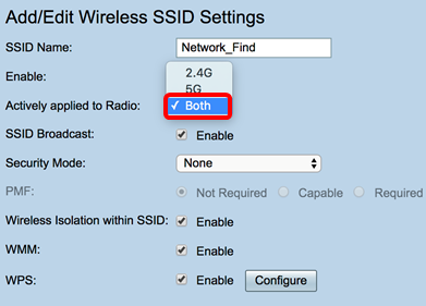
Step 6. (Optional) Check the Enable SSID Broadcast check box to enable visibility to your wireless client devices.

Step 7. Choose the Security Mode from the drop-down menu.
The options are:
- None — This is the default setting. Choosing Disabled will leave the wireless network unsecured so anybody with a wireless client device can connect to the network easily.
- WEP-64 — Wired Equivalent Protection (WEP) is a legacy type of security. A combination of letters from A through F and numbers 0 to 9 may be used in this type of security. Only use this if devices on the network are not compatible with WPA/WPA2.
- WEP-128 — 128-bit password is required for this type of security. Also not recommended as it is not highly secured. Only use this option if devices on the network are not compatible with WPA/WPA2.
- WPA2-Personal — WPA2 is the updated version of Wi-Fi Protected Access (WPA). It uses Advanced Encryption Standard (AES) cipher to protect the wireless network. Like WPA-Personal, WPA2-Personal uses a combination of case-sensitive letters and numbers for the password. This security type is recommended.
- WPA-WPA2-Personal — Allows the router to accommodate wireless clients with both WPA and WPA2-Personal authentication.
- WPA2-Enterprise — Like WPA-Enterprise, this is typically used in enterprise networks. It requires a Remote Authentication Dial-In User Service (RADIUS) to complete this type of wireless security setup. If this is chosen, skip to Step 9.
- WPA-WPA2-Enterprise — Allows the router to accommodate wireless client devices that support both WPA and WPA2. Also typically requires a RADIUS to complete this type of wireless security setup. If this is chosen, skip to Step 9.
Note: In this example, WPA2-Personal is chosen.

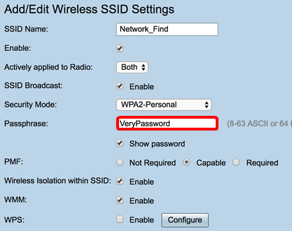
Step 8. If you chose WEP-64, WEP-128, WPA2-Personal, and WPA-WPA2-Personal, enter a password or passphrase in the field provided.
Note: In this example, VeryPassword is the passphrase created for WPA2-Personal.
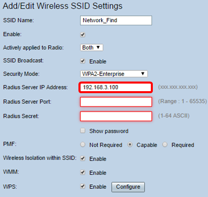
Step 9. If you chose WPA2-Enterprise or WPA-WPA2-Enterprise, follow steps 9 to 11. In the Radius Server IP Address field, enter the IP address of the RADIUS server that the router will contact for authentication.
Note: In this example, 192.168.3.100 is used.
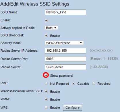
Step 10. In the Radius Server Port field, enter the port number of the RADIUS server.
Note: In this example, 5003 is used as the port number.

Step 11. In the Radius Secret field, enter the secret or password of the RADIUS server.

Step 12. (Optional) Check the Show password check box to display the password in plain text.
Step 13. Click a radio button in the PMF area to allow Protected Management Frames (PMF) for unicast and multicast frames. The options are:
- Not Required — Disables the client support for PMF.
- Capable — Allows both PMF-capable and clients that do not support PMF to join the network. This is the default PMF setting.
- Required — Clients are allowed to associate only if PMF is negotiated. If the devices do not support PMF, they will not be allowed to associate with the network.
Note: In this example, Capable is chosen.

Step 14. Check the Enable Wireless Isolation within SSID check box to allow wireless isolation within the SSID. With wireless isolation enabled, clients connected to the same SSID will not be able to ping each other. In this example, Wireless Isolation with SSID is enabled.

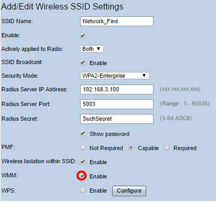
Step 15. Check the Enable WMM check box to enable Wi-Fi Multimedia (WMM). This feature allows you to assign different processing priorities to different types of traffic. You can configure Quality of Service (QoS) to provide different priorities and levels of performance to different applications, users, or data flows.
Step 16. (Optional) Check the Enable WPS check box to allow the client to connect through Wi-Fi Protected Setup (WPS). To learn how to configure WPS, click here.
Note: In this example, the WPS is disabled.

Step 17. Choose the VLAN associated with the SSID from the drop-down list.
Note: In this example, it is left at the default setting, VLAN 1.

Step 18. Choose a time of day from the Time of Day Access drop-down menu for the SSID to function.
Note: In this example, Always On is chosen.

Configure MAC Filtering
Step 19. Check the Enable MAC Filtering to enable the router to filter hosts according to their Media Access Control (MAC) address.

Step 20. (Optional) Click Configure to configure the MAC Filtering.

Step 21. Choose a radio button to either permit or deny users from accessing the wireless network based on their MAC address.
Note: In this example, Prevent PC listed below from accessing the wireless network is chosen.

Step 22. (Optional) Click the Show Client List button to display the list of the connected wireless clients.

The table below displays the following:
- No — The number or sequence of the connected host.
- MAC Address — MAC Address of the connected host.
- IP Address — The Internet Protocol (IP) Address assigned to the connected host.
- Radio — The radio band through which the host is connected.
- Mode — The mode in which the wireless host is connected.
- Authentication — The method which the host authenticated to the network.
- Signal Strength — The strength of the connection between the router and host.
- Noise Level — The level at which the device causes interference.
- Time Connected — The time which the wireless host connected to the SSID.
Note: In this example, there are no clients in the Wireless Client List.

Step 23. Click Close.

Step 24. Enter the MAC address of the client which you want to permit or deny access to the network in the MAC Address field.
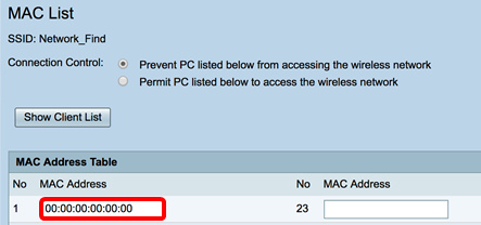
Step 25. Click Apply. You will return to the Add/Edit Wireless SSID Settings page.

Step 26. (Optional) In the Captive Portal area, check the Enable check box if you want to enable the captive portal feature for the SSID. Captive Portal diverts users to a portal to login to before they are given access. This is typically implemented in business centers, malls, coffee shops, airports, and other places that provide public wireless Internet access.

Step 27. (Optional) Choose a captive portal profile in the Portal Profile drop-down list.
Note: In this example, the Default_Portal_Profile is chosen.
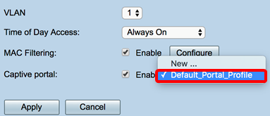
Step 28. Click Apply.
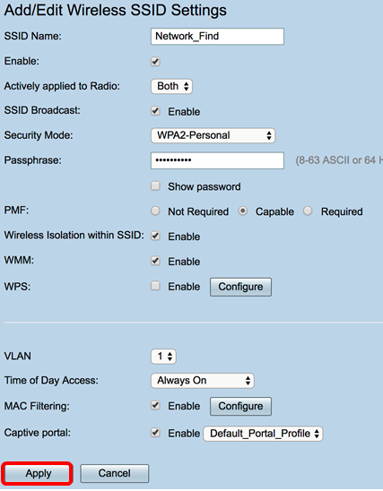
You should see the confirmation message that the configuration settings have been saved successfully. The Wireless Table is now updated with the newly configured network.

You have now successfully configured the Basic Wireless Settings on the RV340W Router.
If you are still getting to know your RV34x routher, you might find this article informative: RV34x Series Router Frequently Asked Questions (FAQs)
 Feedback