Configure a Captive Portal on the RV340W
Available Languages
Objective
The Captive Portal feature provides a convenient, secure, cost-effective way to offer wireless access for clients and other visitors while maintaining the security of your internal network. A guest network can serve many important business purposes, including streamlining business with partners and providing enhanced customer satisfaction and improve employee productivity. A captive portal can be configured on Wireless Access Points (WAPs) and routers with a wireless feature, such as the RV340W.
In a public environment that offers free or paid Wi-Fi, it can be advantageous to a company to have users arrive at a virtual gateway before connecting to the Internet. There are several functions and uses an administrator could have for a captive port. Having a guest network and a virtual gateway can allow users to be redirected to the official page of the company to gain traffic and page views.
This article aims to show you how to configure a Captive Portal profile and associate it to an SSID on the RV340W.
Applicable Devices
- RV340W
Software Version
- 1.0.01.16
Configure Captive Portal
Create a Captive Portal Profile
Step 1. Log in to the web-based utility of the router and choose Wireless > Captive Portal.

Step 2. Click Add to create a new Captive Portal Profile.

Step 3. In the Profile Name field, enter a name for your Captive Portal profile
Note: In this example, Disco is used.
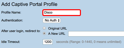
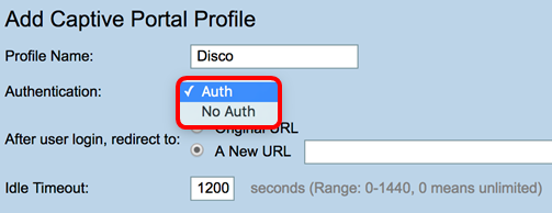
Step 4. From the Authentication drop-down menu, choose whether or not authentication would be required upon entering the Captive Portal. The options are:
- Auth — Choosing this enables authentication upon connecting to the Internet.
- No Auth — Choosing this disables authentication upon arriving at the Captive Portal.
Note: In this example, Auth is chosen.
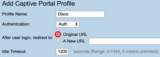
Step 5. In the After user login, redirect to area, choose a radio button to determine the action after a user arrives at the Captive Portal. The options are:
- Original URL — Does not redirect you to a new page upon connecting to the Internet.
- A New URL — Choose this if you want to redirect users to a new page after authentication. Enter a Universal Resource Locator (URL) in the A New URL field.
Note: In this example, Original URL is chosen.
Step 6. Enter a value in seconds in the Idle Timeout field ranging from 0-1440. Setting a limit that the client is allowed to stay connected before they are logged out and re-authentication is required. Entering a value of 0 allows the client to stay connected for an unlimited time period.
Note: In this example, 1201 is used.

Portal Page Customization
Step 7. Choose a color for the font from the Font Color drop-down menu.
Note: In this example, White is chosen.

Step 8. (Optional) In the Background Picture area, click Choose File and choose an image to set as background image for the Captive Portal. If an image is undefined for this step, the captive portal will use the default Cisco background.
Note: In this example, it is left blank. The image format must be in .PNG, .JPG, .BMP. and .GIF. The maximum size is 128 KB.

Step 9. In the Company Name field, enter the company name to be shown on the captive portal page.
Note: In this example, Panikat is used.

Step 10. In the Company Logo Picture area, click Choose File and choose an image to set the Company Logo. If an image is undefined for this step, the captive portal will use the default Cisco logo.

Step 11. In the Welcome Message field, enter the message that is shown when a client is successfully connected.
Note: In this example, Welcome, Earthling! is used as the welcome message.
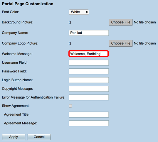
Step 12. (Optional) If you chose Auth in Step 4, enter a text in the labeled Username Field that will be shown next to its corresponding field when they are displayed on the Captive Portal page.
Note: In this example, (first name.last name) is used.
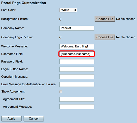
Step 13. (Optional) In Password Field, enter the text that will be shown next to its corresponding field when they are displayed on the Captive Portal page.
Note: In this example, Password is used.

Step 14. In the Login Button Name field, enter the text to be displayed on the login button of the captive portal page.
Note: In this example, Enter the Void is used.


Step 15. In the Copyright Message field, enter a copyright message to be shown at the bottom of the captive portal page.
Note: In this example, © 2017 Disco Networks is used.

Step 16. In the Error Message for Authentication Failure field, enter a message to be displayed when a user fails to authenticate due to an invalid username or password.
Note: In this example, Try again is used.

Step 17. Check the Show Agreement check box to display the terms and agreement message on the Captive Portal page. If you want to leave this unchecked, skip to Step 20.

Step 18. In the Agreement Title field, enter a message to be displayed beside the agreement check box on the Captive Portal page.
Note: In this example, I agree is used.

Step 19. In the Agreement Message field, enter the agreement policy message that will be displayed on the Captive Portal page.
Note: In this example, Terms and Conditions are used.
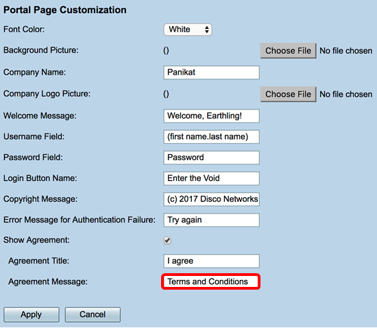
Step 20. Click Apply.

You will be taken to the main Captive Portal configuration page.
Step 21. (Optional) Click Preview to view the recently configured Captive Portal page.

The image below is a preview of the configured Captive Portal.

You should now have successfully configured and customized a Captive Portal profile on the RV340W.
Associate a Captive Portal Profile to a Service Set Identifier (SSID)
Step 1. Login to the web-based utility and choose Wireless > Basic Settings.

Step 2. In the Wireless Table, check the checkbox of the SSID you want to associate to the Captive Portal profile.
Note: In this example, ciscosb2 is chosen.

Step 3. Click Edit.

Step 4. Check the Enable Captive Portal check box.

Step 5. From the Captive portal drop-down list, choose a profile to associate with the SSID.
Note: In this example, Disco is chosen.

Step 6. Click Apply.
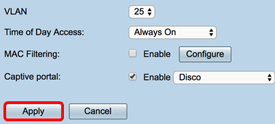
You should now have successfully associated a Captive Portal Profile to an SSID.
 Feedback