Enabling Multiple Wireless Networks on RV320 VPN Router, WAP321 Wireless-N Access Point, and Sx300 Series Switches
Available Languages
Objective
In an ever-changing business environment, your small business network has to be powerful, flexible, accessible, and highly reliable, especially when growth is a priority. The popularity of wireless devices has exponentially grown, which isn't a surprise. Wireless networks are cost-efficient, easy to deploy, flexible, scalable, and mobile, seemlessly providing network resources. Authentication permits network devices to verify and guarantee legitimacy of a user while protecting the network from unauthorized users. It is important to deploy a secure and manageable wireless network infrastructure.
The Cisco RV320 Dual Gigabit WAN VPN Router provides a reliable, highly secure access connectivity for you and your employees. The Cisco WAP321 Wireless-N Selectable-Band Access Point with Single Point Setup supports high-speed connections with Gigabit Ethernet. Bridges connect LANs together wirelessly, making it easier for small businesses to expand their networks.
This article provides step-by-step guidance for the configuration required to enable wireless access in a Cisco small business network, including inter-Virtual Local Area Network (VLAN) routing, multiple Service Set Identifiers (SSIDs), and wireless security settings on the router, switch, and access points.
Applicable Devices
• RV320 VPN Router
• WAP321 Wireless-N Access Point
• Sx300 Series Switch
Software Version
• 1.1.0.09 (RV320)
• 1.0.4.2 (WAP321)
• 1.3.5.58 (Sx300)
Network Topology

The image above illustrates a sample implementation for Wireless access using multiple SSIDs with a Cisco small business WAP, switch and router. The WAP connects to the switch and uses the trunk interface to transport multiple VLAN packets. The switch connects to the WAN router through the trunk interface and the WAN router performs inter-VLAN routing. The WAN router connects to the Internet. All wireless devices connect to the WAP.
Key Features
Combining the Inter-VLAN routing feature provided by the Cisco RV router with the wireless SSID isolation feature provided by a small business access point provides a simple and secure solution for wireless access on any existing Cisco small business network.
Inter-VLAN Routing
Network devices in different VLANs cannot communicate with each without a router to route traffic between the VLANs. In a small business network, the router performs the Inter-VLAN routing for both the wired and wireless networks. When Inter-VLAN routing is disabled for a specific VLAN, hosts on that VLAN will not be able to communicate with hosts or devices on another VLAN.
Wireless SSID Isolation
There are two types of wireless SSID isolation. When Wireless Isolation (within SSID) is enabled, hosts on the same SSID will not be able to see each other. When Wireless Isolation (between SSID) is enabled, traffic on one SSID is not forwarded to any other SSID.
IEEE 802.1x
The IEEE 802.1x standard specifies methods used to implement port-based networks access control that is used to provide authenticated network access to Ethernet networks. Port-based authentication is a process that allows only credential exchanges to traverse the network until the user connected to the port is authenticated. The port is called an uncontrolled port during the time the credentials exchanges. The port is called a controlled port after the authentication is completed. This is based on two virtual ports existing within a single physical port.
This uses the physical characteristics of the switched LAN infrastructure to authenticate devices attached to a LAN port. Access to the port can be denied if the authentication process fails. This standard was originally designed for wired Ethernet networks, however it has been adapted for use on 802.11 wireless LANs.
RV320 Configuration
In this scenario we want the RV320 to act as the DHCP server for the network, so we will need to set that up as well as configure separate VLANs on the device. To start, log in to the router by connecting to one of the Ethernet ports and going to 192.168.1.1 (assuming you have not already changed the IP address of the router).
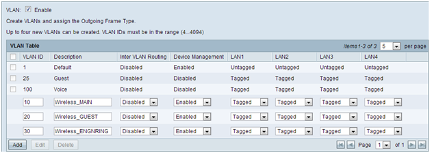
Step 1. Log in to the web configuration utility and choose Port Management > VLAN Membership. A new page opens. We are creating 3 separate VLANs to represent different target audiences. Click Add to add a new line and edit the VLAN ID and Description. You will also need to make sure that the VLAN is set to Tagged on any interfaces that they will need to travel on.
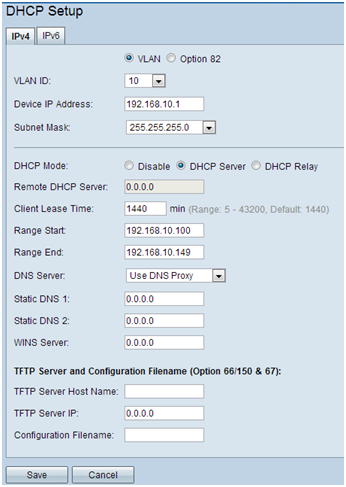
Step 2. Log in to the web configuration utility and select DHCP Menu > DHCP Setup. The DHCP Setup page opens:
- In the VLAN ID drop box, select the VLAN you are setting up the address pool for (in this example VLANs 10, 20, and 30).
- Configure the device IP address for this VLAN, and set the IP address Range. You can also enable or disable DNS proxy here if you wish, and this will be dependent on the network. In this example, DNS Proxy will work to forward DNS requests.
- Click Save and repeat this step for each VLAN.
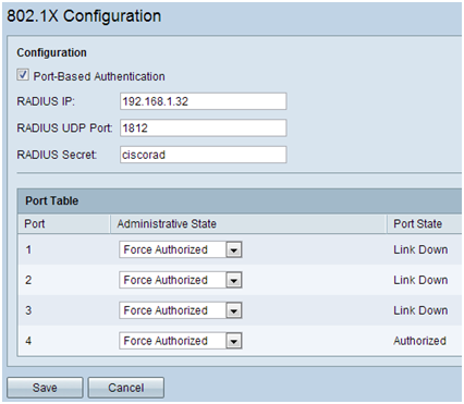
Step 3. On the navigation pane, select Port Management > 802.1x Configuration. The 802.1X Configuration page opens:
- Enable Port-Based Authentication and configure the IP address of the server.
- RADIUS Secret is the authentication key used to communicate with the server.
- Choose which ports will use this authentication and click Save.
Sx300 Configuration
The SG300-10MP switch works as an intermediary between the router and the WAP321 in order to simulate a realistic network environment. The configuration on the switch is as follows.
Step 1. Log in to the web configuration utility, and select VLAN Management > Create VLAN. A new page opens:
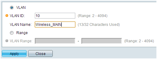
Step 2. Click Add. A new window appears. Enter the VLAN ID and the VLAN Name (use the same as the description from Section I). Click Apply, and then repeat this step for VLANs 20 and 30.
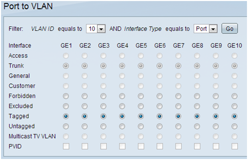
Step 3. On the navigation pane, select VLAN Management > Port to VLAN. A new page opens:
- At the top of the page set the “VLAN ID equals to” to the VLAN you are adding (in this case, VLAN 10) and then click Go on the right. This will update the page with the settings for that VLAN.
- Change the setting on each port so that VLAN 10 is now “Tagged” instead of “Excluded.” Repeat this step for VLANs 20 and 30.
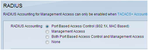
Step 4. On the navigation pane, select Security > Radius . The RADIUS page opens:
- Choose the method of access control to be used by the RADIUS server, either management access control or port-based authentication. Choose Port Based Access Control and click Apply.
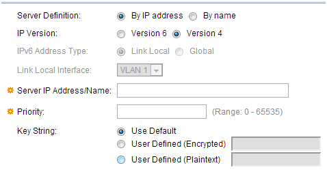
- Click Add at the bottom of the page to add a new server to authenticate to.
Step 5. In the window that appears you will configure the IP address of the server, in this case 192.168.1.32. You will need to set a priority for the server, but since in this example we only have one server to authenticate to the priority does not matter. This is important if you have multiple RADIUS servers to choose from. Configure the authentication key and the rest of the settings can be left as default.
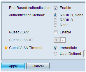
Step 6. On the navigation pane, select Security > 802.1X > Properties. A new page opens:
- Check Enable to turn on 802.1x authentication and choose the authentication method. In this case we are using a RADIUS server so choose the first or second option.
- Click Apply.
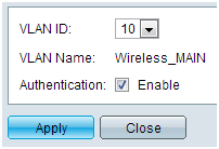
Step 7. Choose one of the VLANs and click Edit. A new window appears. Check Enable to allow authentication on that VLAN and click Apply. Repeat for each VLAN.
WAP321 Configuration
Virtual Access Points (VAPs) segment the wireless LAN into multiple broadcast domains that are the wireless equivalent of Ethernet VLANs. VAPs simulate multiple access points in one physical WAP device. Up to four VAPs are supported on the WAP121 and up to eight VAPs are supported on the WAP321.
Each VAP can be independently enabled or disabled, with the exception of VAP0. VAP0 is the physical radio interface and remains enabled as long as the radio is enabled. To disable operation of VAP0, the radio itself must be disabled.
Each VAP is identified by a user-configured Service Set Identifier (SSID). Multiple VAPs cannot have the same SSID name. SSID broadcasts can be enabled or disabled independently on each VAP. SSID broadcast is enabled by default.
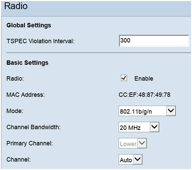
Step 1. Log in to the web configuration utility and select Wireless > Radio. The Radio page opens:
- Click the Enable check box to enable the Wireless Radio.
- Click Save. The Radio will then be turned on.
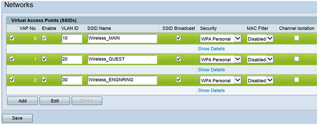
Step 2.On the navigation pane, select Wireless > Networks. The Network page opens:
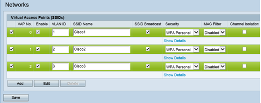
Note: The default SSID for VAP0 is ciscosb. Every additional VAP created has a blank SSID name. The SSIDs for all VAPs can be configured to other values.
Step 3. Each VAP is associated with a VLAN, which is identified by a VLAN ID (VID). A VID can be any value from 1 to 4094, inclusive. The WAP121 supports five active VLANs (four for WLAN plus one management VLAN). The WAP321 supports nine active VLANs (eight for WLAN plus one management VLAN).
By default, the VID assigned to the configuration utility for the WAP device is 1, which is also the default untagged VID. If the management VID is the same as the VID assigned to a VAP, then the WLAN clients associated with this specific VAP can administer the WAP device. If needed, an access control list (ACL) can be created to disable administration from WLAN clients.
On this screen, the following steps should be taken:- Click the check mark buttons on the left side to edit the SSIDs:
- Enter the value needed to the VLAN ID in VLAN ID box
- Click the Save button once the SSIDs have been entered.
Step 4. On the navigation pane, select System Security > 802.1X Supplicant. The 802.1X Supplicant page opens:
- Check Enable in the Administrative Mode field to enable the device to act as a supplicant in 802.1X authentication.
- Choose the appropriate type of Extensible Authentication Protocol (EAP) method from the drop-down list in the EAP Method field.
- Enter the username and password that the access point uses to get authentication from the 802.1X authenticator in the Username and Password fields. The length of the username and password must be from 1 to 64 alphanumeric and symbol characters. This should already be configured on the authentication server.
- Click Save to save the settings.
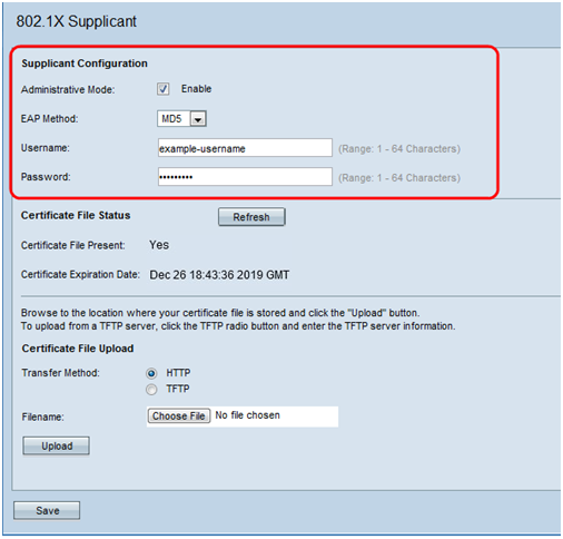
Note: The Certificate File Status area shows whether the certificate file is present or not. The SSL certificate is a digitally signed certificate by a certificate authority that allows the web browser to have a secure communication with the web server. To manage and configure the SSL certificate refer to the article Secure Socket Layer (SSL) Certificate Management on WAP121 and WAP321 Access Points
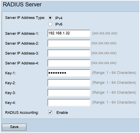
Step 5. On the navigation pane, select Security > RADIUS Server. The RADIUS Server page opens. Enter the parameters, and click the Save button once the Radius Server parameters have been entered.
