Configuring a Site-to-Site VPN Tunnel Between Cisco RV320 Gigabit Dual WAN VPN Router and Cisco 500 Series Integrated Services Adapter
Available Languages
Objective
A Virtual Private Network (VPN) exists as a technology widely used to connect remote networks to a main private network, simulating a private link in the form of an encrypted channel over public lines. A remote network can connect to a private main network as if it exists as a part of the private main network without security concerns because of a 2-phase negotiation that encrypts the VPN traffic in a way that only the VPN endpoints know how to decrypt it.
This short guide provides an example design for building a site-to-site IPsec VPN tunnel between a Cisco 500 Series Integrated Services Adapter and a Cisco RV Series Router.
Applicable Devices
• Cisco RV Series Routers (RV320)
• Cisco 500 Series Integrated Services Adapters (ISA570)
Software Version
• 4.2.2.08 [Cisco RV0xx Series VPN Routers]
Pre-Configuration
Network Diagram
The following shows a Site-to-Site VPN Topology.

A site-to-site IPsec VPN tunnel is configured and established between the Cisco RV Series Router at the Remote Office and the Cisco 500 Series ISA at the Main Office.
With this configuration, a host in LAN 192.168.1.0/24 at the Remote Office and a host in LAN 10.10.10.0/24 at the Main Office can communicate with each other securely over VPN.
Core Concepts
Internet Key Exchange (IKE)
Internet Key Exchange (IKE) is the protocol used to set up a security association (SA) in the IPsec protocol suite. IKE builds on the Oakley protocol, Internet Security Association, and Key Management Protocol (ISAKMP), and uses a Diffie-Hellman key exchange to set up a shared session secret, from which cryptographic keys are derived.
Internet Security Association and Key Management Protocol (ISAKMP)
Internet Security Association and Key Management Protocol (ISAKMP) is used to negotiate the VPN tunnel between two VPN endpoints. It defines the procedures for authentication, communication, and key generation, and is used by the IKE protocol to exchange encryption keys and establish the secure connection.
Internet Protocol Security (IPsec)
IP Security Protocol (IPsec) is a protocol suite for securing IP communications by authenticating and encrypting each IP packet of a data stream. IPsec also includes protocols for establishing mutual authentication between agents at the beginning of the session and negotiation of cryptographic keys to be used during the session. IPsec can be used to protect data flows between a pair of hosts, gateways, or networks.
Design Tips
VPN topology — A point-to-point VPN topology means a secured IPsec tunnel is configured between the main site and the remote site.
Businesses often require multiple remote sites in a multi-site topology, and implement either a hub-and-spoke VPN topology or full mesh VPN topology. A hub-and-spoke VPN topology means that remote sites do not require communication with other remote sites, and each remote site only establishes a secured IPsec tunnel with the main site. A full mesh VPN topology means that remote sites require communication with other remote sites, and each remote site establishes a secured IPsec tunntel with the main site and all other remote sites.
VPN Authentication — The IKE protocol is used to authenticate VPN peers when establishing a VPN tunnel. Various IKE authentication methods exist, and pre-shared key is the most convenient method. Cisco recommends applying a strong pre-shared key.
VPN Encryption — To ensure confidentiality of data transported over the VPN, encryption algorithms are used to encrypt the payload of IP packets. DES, 3DES, and AES are three common encryption standards. AES is considered the most secure when compared to DES and 3DES. Cisco highly recommends applying AES-128 bits or higher encryption (e.g., AES-192 and AES-256). However, stronger encryption algorithms require more processing resources from a router.
Dynamic WAN IP Addressing and Dynamic Domain Name Service (DDNS) — The VPN tunnel needs to be established between two public IP addresses. If the WAN routers receive static IP addresses from the Internet Service Provider (ISP), the VPN tunnel can be implemented directly using static public IP addresses. However, most small businesses use cost-effective broadband Internet services such as DSL or cable, and receive dynamic IP addresses from their ISPs. In such cases, Dynamic Domain Name Service (DDNS) can be used to map the dynamic IP address to a fully qualified domain name (FQDN).
LAN IP Addressing — The private LAN IP network address of each site should have no overlaps. The default LAN IP network address at each remote site should always be changed.
Configuration Tips
Pre-configuration Checklist
Step 1. Connect an Ethernet cable between the RV320 and its DSL or cable modem, and connect an Ethernet cable between the ISA570 and its DSL or cable modem.
Step 2. Turn on the RV320, and then connect internal PCs, servers, and other IP devices to the LAN ports of the RV320.
Step 3. Turn on the ISA570, and then connect internal PCs, servers, and other IP devices to the LAN ports of the ISA570.
Step 4. Make sure to configure the network IP addresses at each site on different subnets. In this example, the Remote Office LAN is using 192.168.1.0 and the Main Office LAN is using 10.10.10.0.
Step 5. Make sure local PCs are able connect to their respective routers, and with other PCs on the same LAN.
Identifying WAN Connection
You will need to know if your ISP provides a dynamic IP address or static IP address. The ISP usually provides a dynamic IP address, but you should confirm this before completing the site-to-site VPN tunnel configuration.
Configuring the Site-to-Site IPsec VPN Tunnel for RV320 at the Remote Office
Step 1. Go to VPN > Gateway-to-Gateway (see picture)
a.) Enter a Tunnel Name, such as RemoteOffice.
b.) Set Interface to WAN1.
c.) Set Keying Mode to IKE with Preshared Key.
d.) Input Local IP Address and Remote IP Address.
The following image shows RV320 Gigabit Dual WAN VPN Router Gateway to Gateway page:

Step 2. Set up IPSec Tunnel Settings (see picture)
a.) Set Encryption to 3DES.
b.) Set Authentication to SHA1.
c.) Check Perfect Forward Secrecy.
d.) Set up the Preshared Key (needs to be the same on both routers).
The following shows IPSec Setup (Phase 1 and 2):

Note: Keep in mind that IPsec Tunnel Settings on both sides of the site-to-site IPsec VPN tunnel must match. If any discrepancies exist between the IPsec Tunnel Settings of the RV320 and the ISA570, both devices will fail to negotiate the encryption key and fail to connect.
Step 3. Click Save to complete the configuration.
Configuring the Site-to-Site IPsec VPN Tunnel for ISA570 at the Main Office
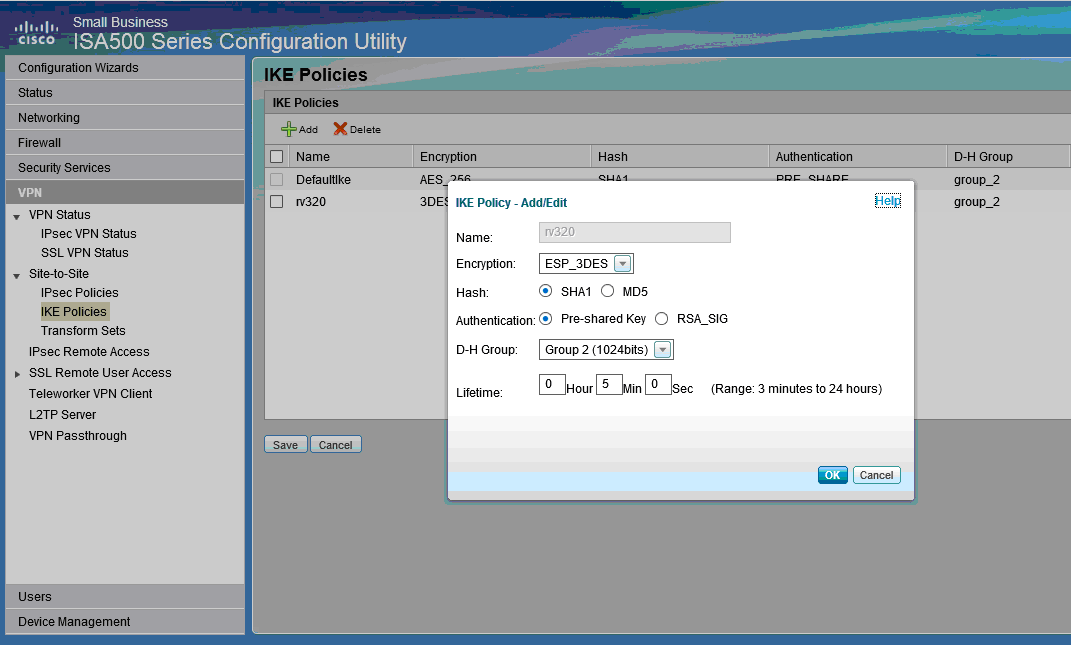
Step 1. Go to VPN > IKE Policies (see picture)
a.) Set Encryption to ESP_3DES.
b.) Set Hash to SHA1.
c.) Set Authentication to Pre-shared Key.
d.) Set D-H Group to Group 2 (1024 bits).
The following image shows IKE Policies:

Step 2. Go to VPN > IKE Transform Sets (see picture)
a.) Set Integrity to ESP_SHA1_HMAC.
b.) Set Encryption to ESP_DES.
The following shows IKE Transform Sets:

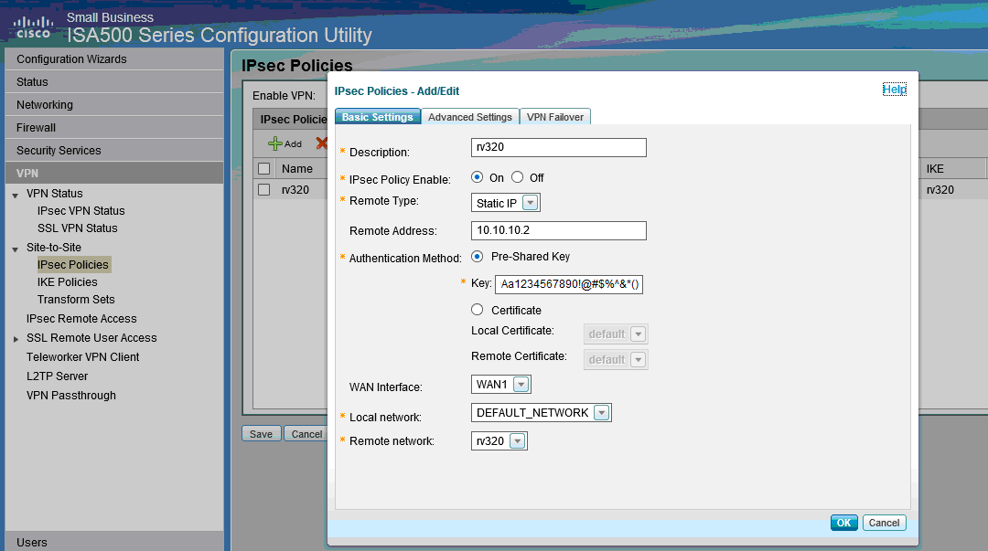
Step 3. Go to VPN > IPsec Policies > Add > Basic Settings (see picture)

Step 4. Go to VPN > IPsec Policies > Add > Advanced Settings (see picture)
a.) Set IKE Policy and IKE Transform Sets respectively to those created in Steps 1 and 2.
b.) Set SA-Lifetime to 0 Hour 5 Min 0 Sec.
c.) Click OK.
The following shows IPsec Policies Advanced Settings:

Step 5. Connect site-to-site IPsec VPN Tunnel (see picture)
a.) Set Enable VPN to On.
b.) Click Connect button.
The following image shows the Connect Button:

 Feedback