Configure System Settings on the Cisco Business Dashboard
Available Languages
Objective
Cisco Business Dashboard Probe equips a network administrator with indispensable tools that help securely monitor and manage Cisco devices from a web browser.
The system configuration page allows you to define various system level parameters that typically apply to all devices in the network. These parameters include configurations such as time settings, domain name services, and administrator authentication. You may create configuration profiles for each of these areas separately, or you may use the wizard to create profiles for each area in a single workflow. The configuration profiles are then applied to one or more device groups and then pushed out to the devices.
This document assumes that all devices have Simple Network Management Protocol (SNMP) enabled. Cisco Business Dashboard Network Management is a web-based network manager that uses SNMP to monitor and manage nodes or devices on the network. These nodes or devices must have SNMP enabled to communicate with the Cisco Business Dashboard Network Manager.
This document aims to show you how to configure the system settings on a device group via the Wizard and manual configuration in the Cisco Business Dashboard Probe.
Applicable Software Version
- CBD (Data Sheet) | 2.2 (Download latest)
Configure System Settings
Wizard Configuration
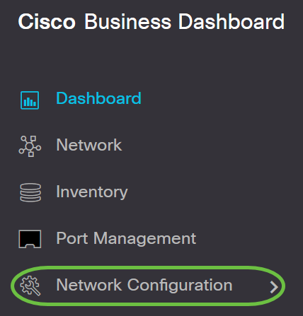
Step 1. Log in to the Cisco Business Dashboard and choose Network Configuration >
Wizard.

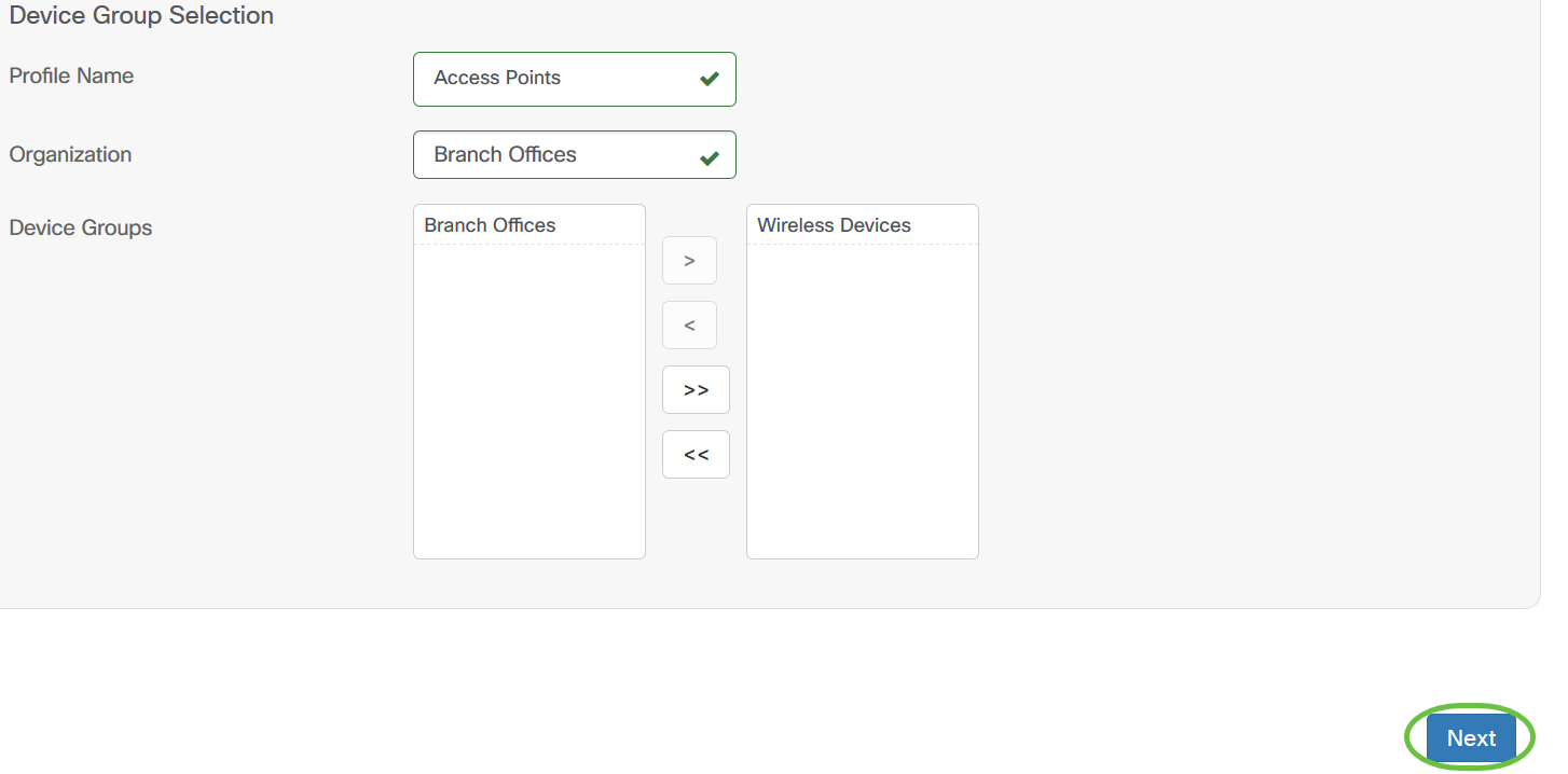
Step 2. In the Device Group Selection, enter a description for the configuration profile in the Profile Name field. This part of the configuration is requisite and cannot be skipped.
Note: For this example, Access Points is used.

Step 3. In the Device Group area, choose the device group to be configured and click
the  to map it. If no new groups have been configured, the default device
group containing all network devices will be present in the Device Group area. If you want to know how to
create a new device group, click here
for instructions.
Note: For this example, Wireless Devices is chosen.

Step 4. Click Next.
Step 5. In the Timezone drop-down menu, choose the time zone where your network is located.
Note: For this example, America/New York (GMT-4:00) is used.

Step 6. (Optional) Check the Enable Daylight Saving check box if your country observes Daylight Savings Time (DST).

Step 7. Choose a Daylight-Saving Mode by clicking a radio button.
The options are:
- By Date - Choose this mode to specify parameters for DST according to specific days and time of the year.
- Recurring - Choose this mode to set DST to occur between two days of different months.
Note: For this example, Recurring was chosen.

Step 8. If you chose Recurring in Step 7, in the Month field, enter a number corresponding to the month of the year you want DST to begin. Use numbers between 1-12.
Note: Numbers entered in this field must not be greater than the numbers entered in the To field.

Step 9. In the Week field, enter the week of the month you want DST to begin.
Note: For this example, 2 is used to show the 2nd week of the month.

Step 10. From the Day drop-down menu, click the day of the week, which you want DST to begin.
Note: For this example, Sunday is used.

Step 11. In the Time drop-down list, use the up or down arrow to choose the time of the day in which you want DST to begin.
Note: In this example, 6:57AM is used.

Step 12. In the To area, repeat the steps from Step 12 to Step 15 to specify the month, week, day, and time you want DST to end
Note: In this example, DST is set to end on November 1st week on a Sunday at 06:59PM.

Step 13. From the Daylight Saving Offset drop-down list, choose the number of minutes that DST should offset the current time. The options are +15, +30, +45, and +60.
Note: For this example, +45 is used.

Step 14. Check the Use NTP check box to configure the system to resource time from the Network Time Protocol (NTP) server.

Step 15. In the NTP Server1 field, enter an NTP server address. A host name can consist of one or more labels, which are sets of up to 63 alphanumeric characters. If a host name includes multiple labels, each is separated by a period. A green checkmark appears in the field if the entered NTP server address is valid.
Note: For this example, test.cisco.com is used.
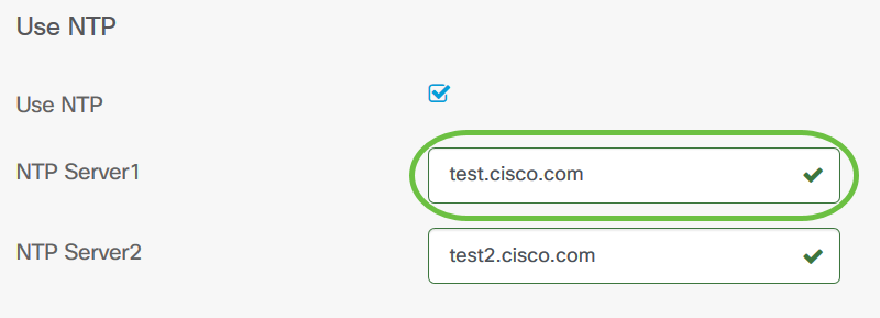
Step 16. (Optional) Enter a second NTP server address in the NTP Server2 field. This serves as a backup in case NTP Server1 fails to sync to the network. A green checkmark will appear in the field if the entered NTP server address is valid.
Note: In this example, test2.cisco.com is used.

Step 17. Click Next to proceed, or Skip if you want to skip this part of the configuration.

Step 18. (Optional) In the Domain Name field, enter the Domain Name System (DNS) name. A green checkmark will appear in the field if the entered domain name is valid.
Note: For this example, resolver1.cisco.com is used as the domain name.
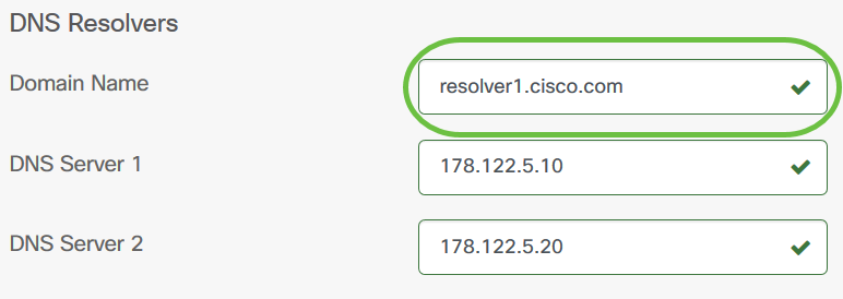
Step 19. In the DNS Server1 field, enter the DNS server address. This is an Internet Protocol version 4 (IPv4) address. A green checkmark will appear in the field if the entered DNS server address is valid. If you already have DNS server addresses from your Internet Server Provider (ISP), enter the address found in the router.
Note: For this example, 178.122.5.10 is used.
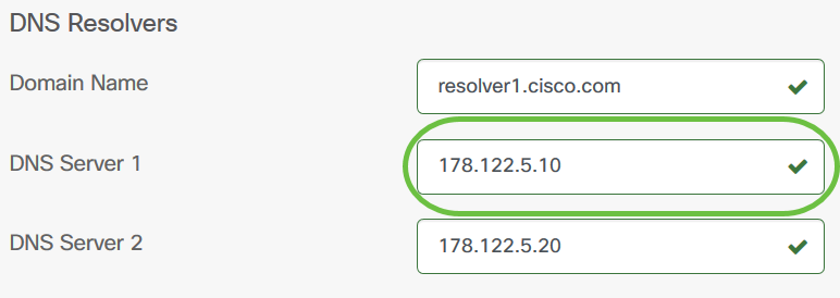
Step 20. (Optional) Enter a backup DNS server address that will serve as a failover if the primary server is unreachable. A green checkmark will appear in the field if the entered DNS server address is valid.
Note: In this example, 178.122.5.20 is used.
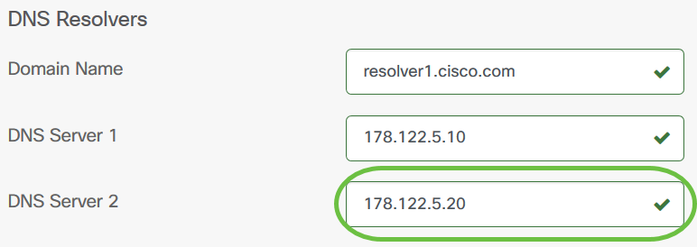
Step 21. Click Next to continue or Skip to skip this part of the configuration.

Step 22. Create a local username and password in the Username and Password fields. These are administrative user access to network devices. If there are existing local users on the devices, then they will be replaced by configuring users below. To create multiple users, click the + (add) icon.
Note: A total of four local user credentials may be created. For this example, only one local user is created.
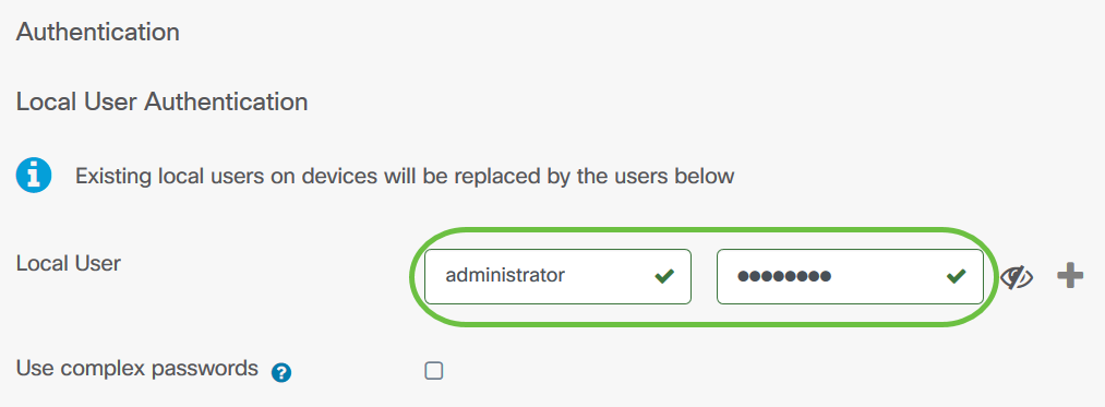
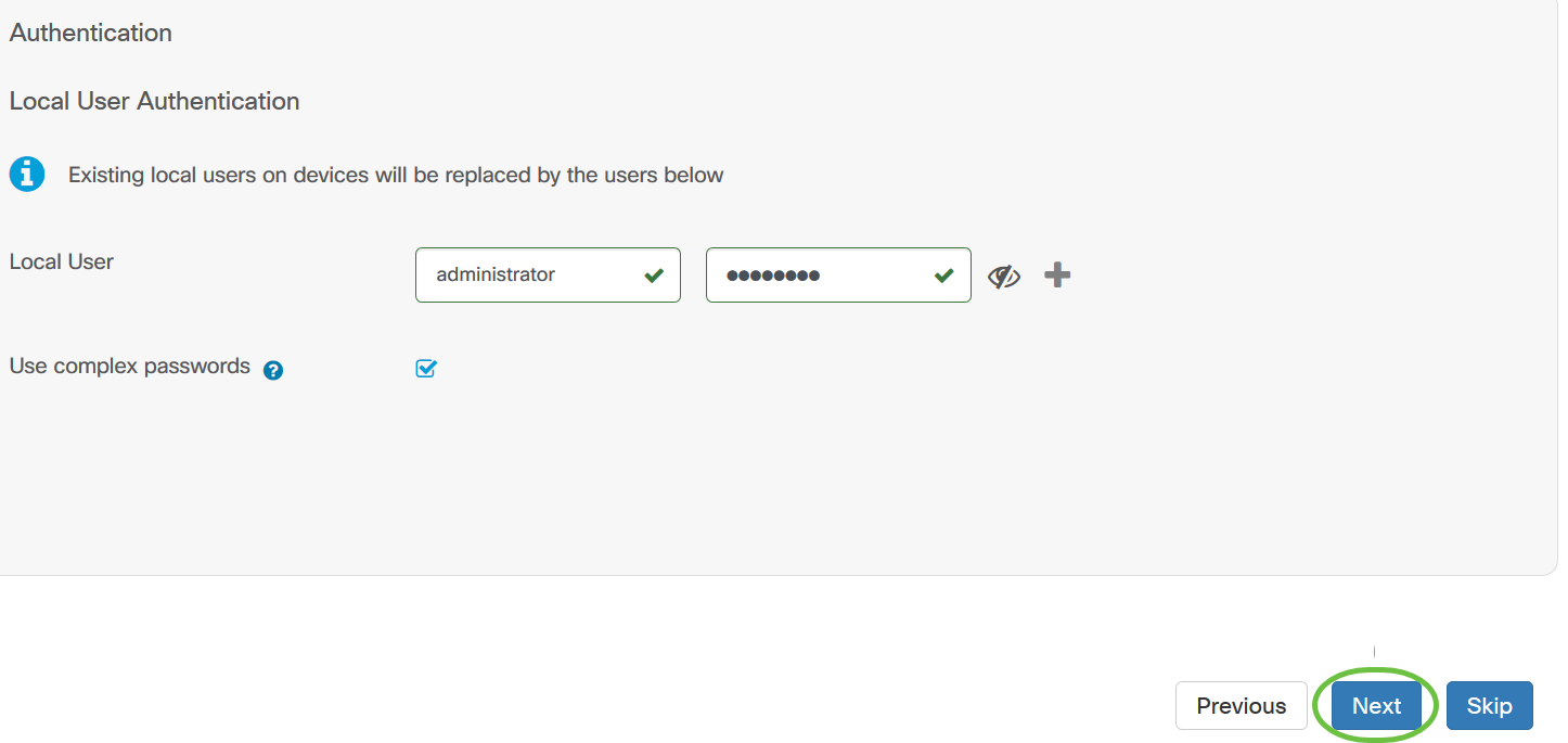
Step 23. (Optional) Check the Use complex passwords check box to enable or disable password checking.

Step 24. Click Next.
Step 25. Click the plus icon to add a new VLAN.

Step 26. Specify a descriptive name for the VLAN, and the VLAN ID to be used. The VLAN ID should be a number in the range 1-4094.
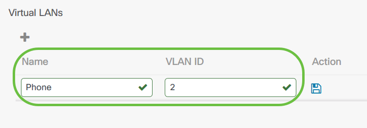
Step 27. Click the Save icon. The new VLAN will be created on all VLAN-capable devices in the selected groups.
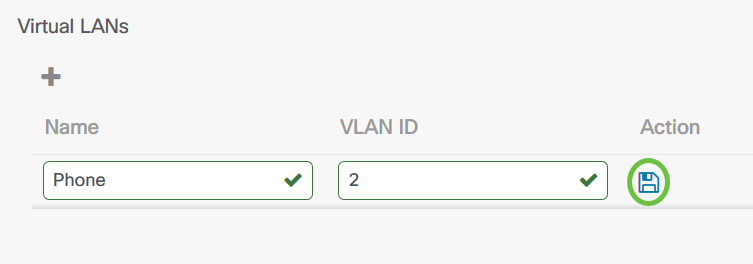
Note: You may create multiple VLANs using a single profile. If you want to create additional VLANs in this profile, click the plus icon.
If the VLAN ID of the newly created VLAN matches an existing VLAN already present on devices in the device group, that VLAN will be adopted by Cisco Business Dashboard and removed from the discovered Virtual LANs table.
Step 28. Click Next to continue or Skip to skip this part of the configuration.
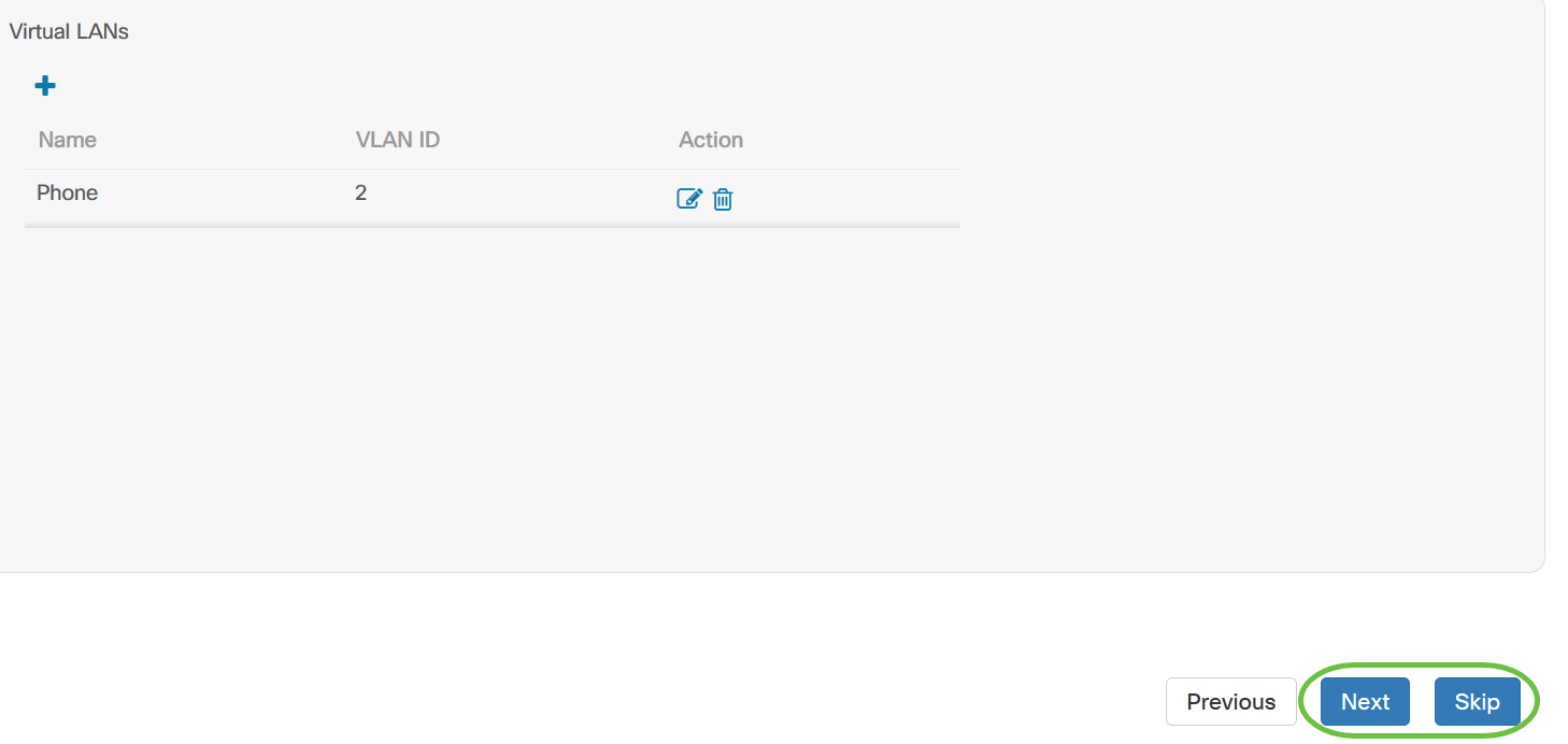
Step 29. Click the plus icon to add a new Wireless LAN.
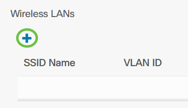
Step 30. Specify an SSID name for the Wireless LAN, and the VLAN ID that it should be associated with. The VLAN ID should be a number in the range 1-4095, and if it does not already exist in the network, a new VLAN will be created automatically.

Step 31. Optionally change the Enable, Broadcast, Security and Radio settings to match your requirements.

Step 32. Depending on whether you select Enterprise or Personal security mode, specify either the RADIUS server to be authenticated against, or a pre-shared key.

Step 33. Click Save.The new WLAN will be created on all devices with wireless access point capabilities in the selected groups.
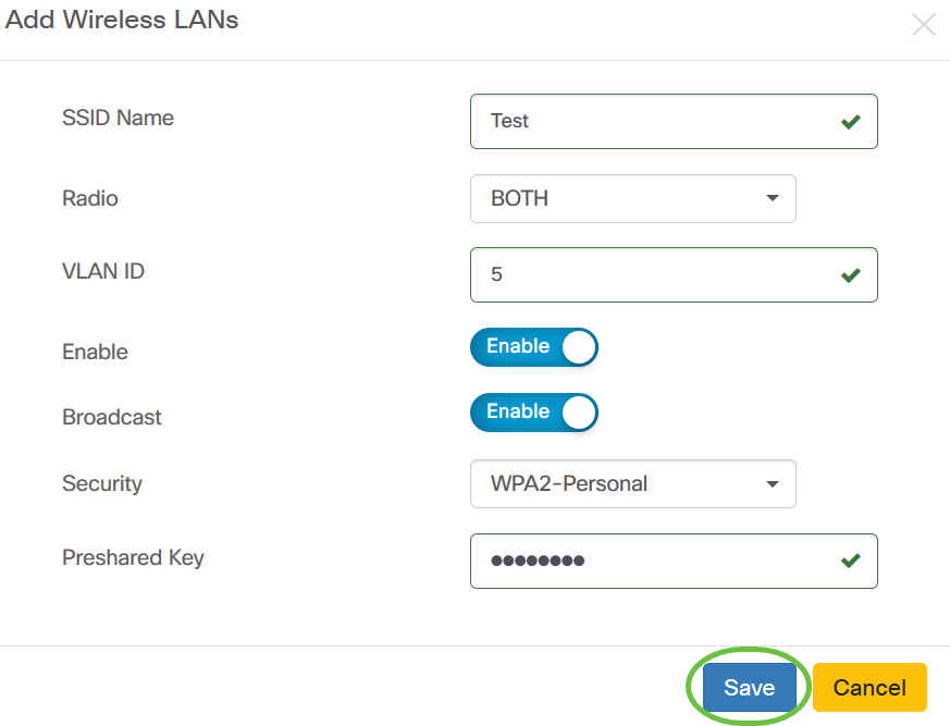
Step 34. Click Next to continue or Skip to skip this part of the configuration.

Step 35. Click Finish to save your configuration. If you want to go back to the previous configuration page to make changes, click Previous.

You should now have created or added a new system configuration profile of your device group through the Wizard.
Manual Configuration
Configure Time Setting
Step 1. In the Navigation pane, choose Network Configuration > Time Management.

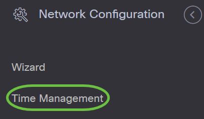
Step 2. Click the + (add) icon to create a new profile.
Note: If you want to modify an existing profile, click the radio button of the profile you want to modify and click the Edit icon located on the top left corner of the work pane.

Step 3. Under the Device Group Selection area, enter a description for the configuration in the Profile Namefield.
Note: For this example, Access Points is used.

Step 4. In the Device Group area, choose the device group to be configured and click
the  to map it. More than one group may be chosen.
Note: For this example, Wireless Devices is used.

Step 5. In the Timezone drop-down menu, choose the time zone where your network is located.
Note: For this example, America/New York (GMT-4:00) is used.

Step 6. Check the Enable Daylight Saving check box if your country observes Daylight Savings Time (DST).
Note: Not all time zones use DST.

Step 7. Choose a Daylight-Saving Mode by clicking a radio button.
The options are:
- By Date - Choose this mode to specify parameters for Daylight Savings Time (DST) according to specific days and time of the year. If you chose this, skip to Step 8.
- Recurring - Choose this mode to set DST to occur between two days of different months. If you chose this, skip to Step 11.

Step 8. If you chose By Date in Step 7, click the calendar in the Range to choose the day, month, year, and time you want DST to begin. Click OK.

Note: Click the up or down arrow to choose the time of the day you want DST to begin.
Step 9. If you chose Recurring in Step 7, in the Month field, enter a number corresponding to the month of the year you want DST to begin. Use numbers between 1-12.
Note: Numbers entered in this field must not be greater than the numbers entered in the To field.

Step 10. In the Week field, enter the week of the month you want DST to begin.
Note: For this example, 2 is used to show the 2nd week of the month.

Step 11. From the Day drop-down menu, click the day of the week, which you want DST to begin.
Note: For this example, Sunday is used.

Step 12. In the Time drop-down list, use the up or down arrow to choose the time of the day in which you want DST to begin.
Note: In this example, 6:57 AM is used.

Step 13. In the To area, repeat the steps from Step 11 to Step 14 to specify the month, week, day, and time you want DST to end.
Note: In this example, DST is set to end on November 1st week on a Sunday at 06:59 PM.

Step 14. From the Daylight Saving Offset drop-down list, choose the number of minutes that DST should offset the current time. The options are +15, +30, +45, and +60.
Note: In this example, +45 is used as the offset.

Step 15. Check the Use NTP check box to configure the system to resource time from the NTP server.

Step 16. In the NTP Server1 field, enter an NTP server address. A host name can consist of one or more labels, which are sets of up to 63 alphanumeric characters. If a host name includes multiple labels, each is separated by a period. A green checkmark appears in the field if the entered NTP server address is valid.
Note: For this example, test.cisco.com is used.

Step 17. (Optional) Enter a second NTP server address in the NTP Server2 field. This serves as a backup in case NTP Server1 fails to sync to the network. A green checkmark will appear in the field if the entered NTP server address is valid.
Note: In this example, test2.cisco.com is used.

Step 18. Click Save if this is a new configuration.
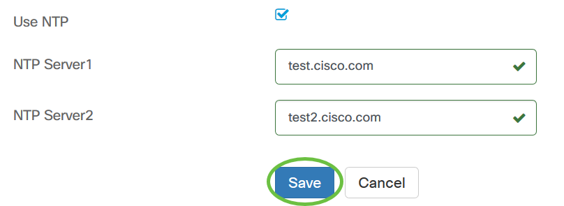
You should now have successfully created or modified the time settings of your device group manually.
Configure DNS Resolvers
Step 1. In the Navigation pane, choose Network Configuration > DNS Resolvers.


Step 2. Click the + (add) icon to create a new profile. If you want to modify an existing profile, click the radio button of the profile you want to modify and click the Edit icon located on the top left corner of the work pane.
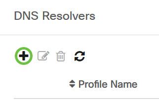
Step 3. Under the Device Group Selection area, enter a description for the configuration in the Profile Namefield.
Note: For this example, Access Points is used.

Step 4. In the Device Group area, choose the device group to be configured and click
the  to map it. More than one group may be chosen.
Note: For this example, Wireless Devices is used.

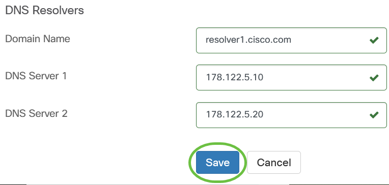
Step 5. In the Domain Name field, enter the DNS name. A green checkmark will appear in the field if the entered domain name is valid.
Note: For this example, resolver1.cisco.com is used.

Step 6. In the DNS Server1 field, enter the DNS server address. This is an Internet Protocol version 4 (IPv4) address. A green checkmark will appear in the field if the entered DNS server address is valid. If you already have DNS server addresses from your Internet Server Provider (ISP), enter the address found in the router.
Note: For this example, 178.122.5.10 is used.

Step 7. (Optional) Enter a backup DNS server address that will serve as a failover if the primary server is unreachable. A green checkmark will appear in the field if the entered DNS server address is valid.
Note: For this example, 178.122.5.20 is used.

Step 8. Click Save if this is a new configuration.
You should now have successfully created or modified the DNS settings of your device group manually.
Configure Authentication
Step 1. In the Navigation pane, choose Network Configuration > Authentication.


Step 2. Click the + (add) icon to create a new profile. If you want to modify an existing profile, click the radio button of the profile you want to modify and click the Edit icon located on the top left corner of the work pane.
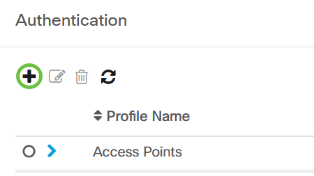
Step 3. Under the Device Group Selection area, enter a description for the configuration in the Profile Namefield.
Note: For this example, Access Points is used.

Step 4. In the Device Group area, choose the device group to be configured and click
the to  map it. More than one group may be chosen.
Note: For this example, Wireless Devices is used.

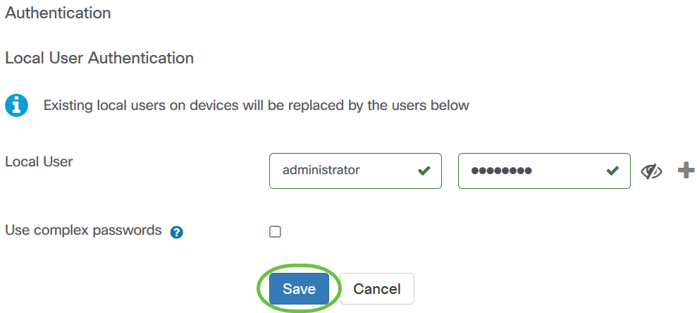
Step 5. Create a local username and password in the Username and Password fields. If there are existing local users on the devices, then they will be replaced by configuring users below. These are administrative user access to network devices. To create multiple users, click the + (add) icon.
Note: A total of four local user credentials may be created. For this example, only one local user is created.

Step 6. Click Save if this is a new configuration.
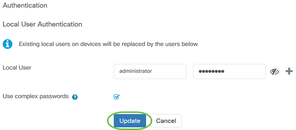
If you are modifying an existing configuration, click Update.
You should now have successfully configured or modified your device group authentication settings manually.
Contact Cisco
- Open a Support Case

- (Requires a Cisco Service Contract)
 Feedback