Introduction
This document describes how to troubleshoot, collect logs, and recommend actions required for the RAID Controller issue in the Cisco UCS environment.
Prerequisites
Requirements
There are no specific requirements for this document.
Component Used
The information in this document is based on these software and hardware versions:
- Unified Computing System (UCS)
- Cisco Unified Computing System Manager (UCSM)
- Redundant Array of Independent Disks (RAID) Controller
The information in this document was created from the devices in a specific lab environment. All of the devices used in this document started with a cleared (default) configuration. If your network is live, ensure that you understand the potential impact of any command.
Known UCSM Faults Codes
UCSM Fault:F1004
Description: Controller X on server X is inoperable. Reason: Device non-responsive.
UCSM Fault:F1004
Description: Controller 1 on server 2 is inoperable. Reason: Device reported corrupt data.
UCSM Fault: F1007
Description: Virtual drive X on server X operability: inoperable. Reason: Drive state: unknown.
UCSM Fault: F0181
Description: Local disk 1 on server 3/4 operability: inoperable. Reason: Drive state: unknown.
UCSM Fault: F1834
Description: Controller 1 on server 2/7 is degraded. Reason: controller-flash-is-degraded.
Replace RAID Controller
When you replace a RAID controller, the RAID configuration that is stored in the controller is lost. Use this procedure to restore your RAID configuration to the new RAID Controller.
Legacy Mode
Step 1. Power off the server, replace your RAID controller.
Warning: If it is a full chassis swap, replace all drives into the drive bays in the same order that they were installed in the old chassis. Label each disk order before you remove the drives from the present chassis.
Step 2. Reboot the server and watch for the prompt to press F.
Press F when you see this on-screen prompt.
Foreign configuration(s) found on adapter.

Press any key to continue or 'C' load the configuration utility, or 'F' to import foreign configuration(s)
Note: Before replacing the RAID controller, the VD can be optimal and accessible from the host.
UEFI Boot Mode
Step 1. Check if the server is configured in Unified Extensible Firmware Interface (UEFI) mode.
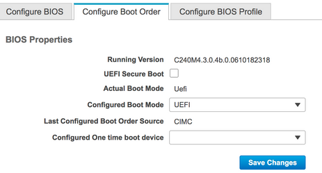
Step 2. Power off the server, replace your RAID controller.
Warning: If it is a full chassis swap, replace all drives into the drive bays in the same order that they were installed in the old chassis. Label each disk order before you remove the drives from the present chassis.
Step 3. Reboot the server and watch for the F2 Prompt.
Step 4. Press F2 when prompted to enter the BIOS Setup utility.
Step 5. Under Setup Utility, navigate to Advanced > Select controller > Configure, and click Import foreign configuration to Import.
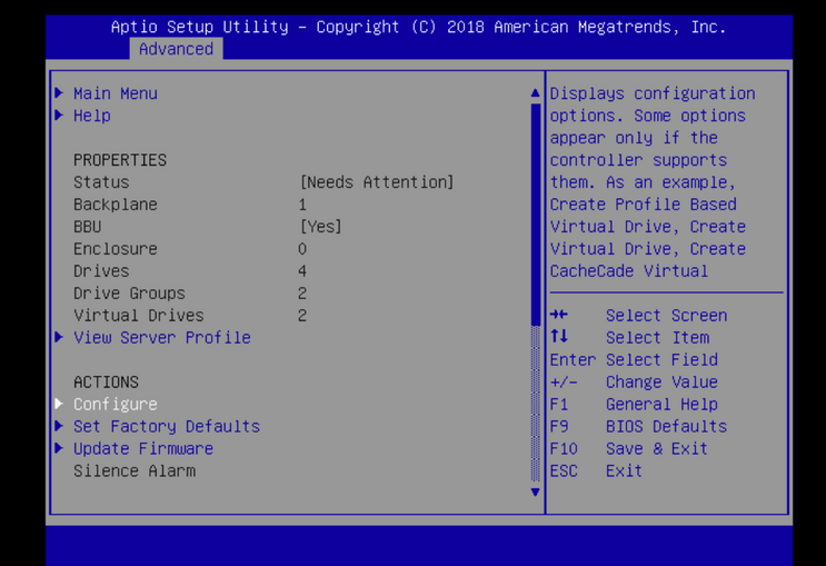
Note: Before replacing the RAID controller, the VD can be optimal and accessible from the host.
Logs To Be Collected
Please ensure you have these logs attached to the TAC case.
- Server _techsupport
- UCSM_techsupport (if applicable)
- OS logs and Driver details
- LSIget / storcli logs
- Screenshot, if applicable ( example PSOD)
Note: If the Controller does not respond, storcli logs capture nothing. Reboot the server and then collect the Storcli logs, if the Controller starts responding. If still no response, collect server_techsupport before and after the reboot of the server.
How To Collect Storcli Logs
LSIGET is the script that runs all the commands for the utilities.STORCLI is the utility itself.
Note: Always download and use the latest Lsiget from the Broadcom website.
OS Is Installed
Linux OS:
In order to install StorCLI on Linux operating systems, perform these steps.
- Unzip the StorCLI package.
- To install the StorCLI RPM, run the rpm -ivh <StorCLI-x.xx-x.noarch.rpm> command.
- To upgrade the StorCLI RPM, run the rpm -Uvh <StorCLI-x.xx-x.noarch.rpm> command.
Commands to capture:
./storcli /c0 /eall show phyerrorCounters > Phy.txt

./storcli /c0 show termlog > Termlog.txt

./storcli /c0/eall/sall show all > PD.txt

./storcli /c0/vall show all > VD.txt

./storcli/c0 show eventloginfo > eventlog.txt

./storcli /c0 show pdfailevents > PDFailEvents.txt
Download LSIget script for Linux OS.
Broadcom Support and Services
ESXI OS
Step 1. Download Storcli Utility from here: Broadcom Docs Download
Step 2. Copy the storcli.vib from the source folder to the ESXi datastore. Check the readme file and use the corresponding VIB file.
Step 3. Install storcli utility as shown here. You need to specify the complete path to the datastore where the VIB is located.
esxcli software vib install -v /vmfs/volumes/<datastore>/vmware-esx-storcli.vib --no-sig-check
Step 4. Navigate to /opt/lsi/storcli directory and execute any storcli command to check if the utility is able to collect the logs.
Example: ./storcli /c0 show all
Step 5. Download the LSIget utility from this link.
Broadcom Support and Services
Step 6. Select the VMware Version.
Step 7. Copy the file onto the host OS datastore.
Step 8. Run the command tar -zxvf lsigetvmware_062514.tgz (corrected for the filename/version downloaded).
Sample Output on ESXi 6.0:
/vmfs/volumes/52a767af-784a790c-3505-a44c1129fe2c/LSI # tar -zxvf lsigetvmware_062514.tgz
/vmfs/volumes/52a767af-784a790c-3505-a44c1129fe2c/LSI # ls
lsigetvmware_062514      lsigetvmware_062514.tgz
/vmfs/volumes/52a767af-784a790c-3505-a44c1129fe2c/LSI # cd lsigetvmware_062514/
/vmfs/volumes/52a767af-784a790c-3505-a44c1129fe2c/LSI/lsigetvmware_062514 # ls
Readme.txt      all_cli         lsigetlunix.sh
/vmfs/volumes/52a767af-784a790c-3505-a44c1129fe2c/LSI/lsigetvmware_062514 # ./lsigetlunix.sh
The ./lsigetlunix.sh -D -Q version of the command can be used to run the script in Quiet Mode to reduce production impact.
Step 9. Once the tool successfully completes, it generates a tar.gz file. Attach this file to the TAC case in the way a normal Tech Support bundle is uploaded.
OS Is Not Installed
Download Storcli tool: Broadcom Support and Services
Step 1. Download Storcli from Management Softwares and Tools (link), extract the folder and navigate to the EFI folder. Get the Storcli file with .EFI extension, as shown in the image.


Step 2. Create a new folder by any name. Here it is created by the name EFI and storcli.efi is copied in that folder.
Launch KVM of the server, and as shown in the image, navigate to Virtual Media create image option.
Browse to provide source folder on Create Image from Folder pop up. Source folder selected here is the EFI folder which was created earlier, it contains the storcli.efi file.
Also, browse the destination path for the IMG file. As shown in the image, click Finish to create the IMG file.
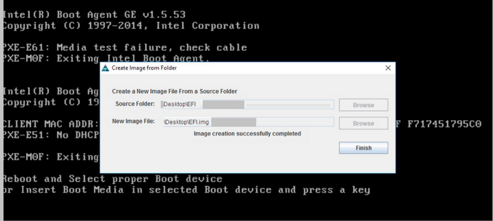
Note: JAVA based KVM was used here to convert from storcli.efi to EFI.IMG.
Step 3. Launch KVM, attach efi.img.

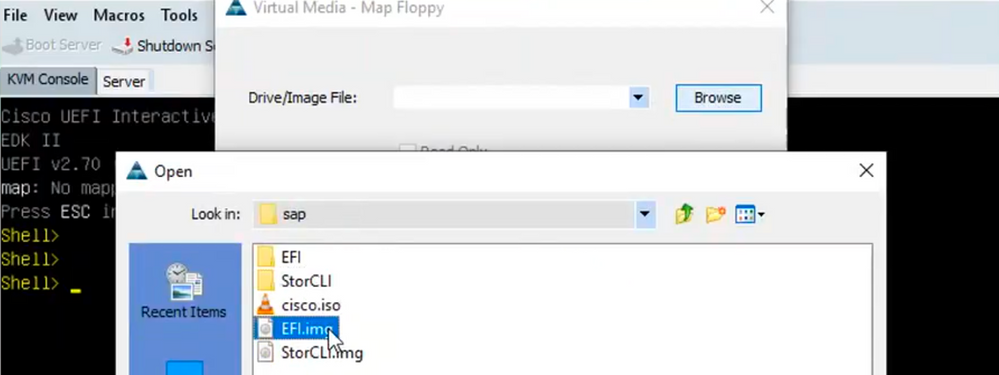
Step 4. Map the EFI Image.
Note: Do Not tick the check of READ ONLY.

How to Convert Storcli.efi to efi.IMG File using HTML5 KVM
Background
Starting with CIMC/UCSM 4.1, the Java KVM is no longer available to create read/write image files. Also, JAVA based KVM can no longer be available starting CIMC/UCSM 4.1.
Detailed Steps
Step A: You need a linux machine to perform these steps.
Step B : [root@localhost /]# dd if=/dev/zero of=hdd.img bs=1024 count=102400
102400+0 records in
102400+0 records out
104857600 bytes (105 MB) copied, 0.252686 s, 415 MB/s
Step C: [root@localhost /]# mkfs.msdos hdd.img
mkfs.fat 3.0.20 (12 Jun 2013)
Note: If you do not see the MSDOS as an extension, then you would need to install the respective .RPM as shown here. Use Yum list to see if the package is there, otherwise, you would need to download one from Internet or from redhat.
[root@localhost /]# rpm -ivh dosfstools-3.0.20-10.el7.x86_64.rpm
warning: dosfstools-3.0.20-10.el7.x86_64.rpm: Header V3 RSA/SHA256 Signature, key ID f4a80eb5: NOKEY
Preparing... ################################# [100%]
Updating / installing...
1:dosfstools-3.0.20-10.el7 ################################# [100%]
Step D : Mount the hdd.img
[root@localhost /]# mount -oloop hdd.img /mnt/hdd
Step E: Copy the required files (storecli.efi file )
[root@localhost EFI]# cp storcli.efi /mnt/hdd
[root@localhost EFI]#
[root@localhost EFI]# ls
storcli.efi
Step F: Umount /mnt/hdd
[root@localhost EFI]# umount /mnt/hdd
Step G: Verifying the hdd.img type. Browse to the directory and run the command shown here.
[root@localhost /]# file hdd.img
hdd.img: x86 boot sector, mkdosfs boot message display, code offset 0x3c, OEM-ID "mkfs.fat", sectors/cluster 4, root entries 512, Media descriptor 0xf8, sectors/FAT 200, heads 64, sectors 204800 (volumes > 32 MB) , reserved 0x1, serial number 0x6f39955b, unlabeled, FAT (16 bit)
Step H :Using Winscp or any other file transfer tool, copy the image and transfer it to the desired system.
Step I: Launch the HTML5 KVM. Click activate virtual devices > Removable disk > Browse to select hdd.img copied from Linux machine and click map drive.
Step 5. After booting into EFI shell, run this command map -r, as shown in the image.

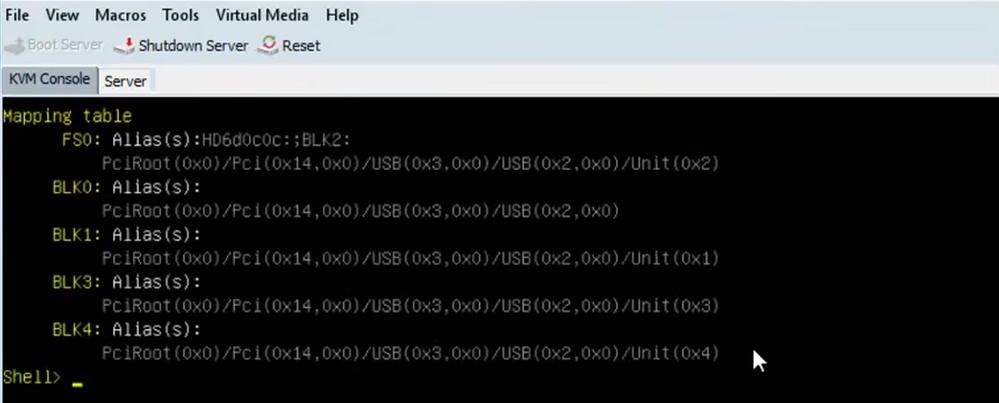
Step 6. Run this command fs<X>: where X = controller number that was received from the mapping table.

Step 7. Run command cd EFI.

Step 8. Type ls to confirm the storcli.efi is present. Run the command Storcli.efi show to confirm you are inside the correct Raid Controller. You can now see a directory structure with storcli.efi available and can run storcli.efi commands from here.

Run these Commands to collect the logs:
storcli.efi /c0/vall show all >showall.txt

storcli.efi /c0/vall show all > vall.txt

storcli.efi /c0/eall show all >eall.txt

storcli.efi /c0 show termlog > termlog.txt

storcli.efi /c0/eall/sall show all > showall.txt

storcli.efi /c0 show events file > Events.txt

storcli.efi /c0/eall show phyerrorcounters > phy.txt

storcli.efi /c0 show snapdump

storcli.efi /c0 get snapdump id=all file=snapdump.zip

Storcli.efi /c0 show pdfailevents file=pdfailevents.txt
At this point, you need to get the files to Cisco TAC for analysis. Unmount the .img file, and upload the logs to the Cisco TAC case.
Virtual Drive States And Recommended Steps
Virtual Drive is optimal-The virtual drive operating condition is good. All configured drives are online.
No Action needed.
Virtual Drive is degraded- The virtual drive operating condition is not optimal. One of the configured drives has failed or is offline.
Action to be performed- Replace the drive as soon as possible. First, take Backup of the data.
Virtual Drive is Partially degraded- The operating condition in a RAID 6 virtual drive is not optimal. One of the configured drives has failed or is offline. RAID 6 can tolerate up to two drive failures.
Action to be performed- Replace the drive as soon as possible.
Virtual Drive is offline- The virtual drive is not available to the RAID controller. This is essentially a failed state.
Action to be performed- Bring the RAID back to the degraded state and backup the data. Replace the drive soon.
Virtual Drive is offline and new storage controller-The virtual drive is not available to the RAID controller. This is essentially a failed state.
Action to be performed-Do not replace the storage controller. Contact TAC for assistance.
Related Information


 Feedback