IOS Router : Auth-proxy Authentication Inbound with ACS for IPSec and VPN Client Configuration
Available Languages
Download Options
Bias-Free Language
The documentation set for this product strives to use bias-free language. For the purposes of this documentation set, bias-free is defined as language that does not imply discrimination based on age, disability, gender, racial identity, ethnic identity, sexual orientation, socioeconomic status, and intersectionality. Exceptions may be present in the documentation due to language that is hardcoded in the user interfaces of the product software, language used based on RFP documentation, or language that is used by a referenced third-party product. Learn more about how Cisco is using Inclusive Language.
Contents
Introduction
The authentication proxy feature allows users to log in to a network or access the Internet via HTTP, with their specific access profiles automatically retrieved and applied from a TACACS+ or RADIUS server. The user profiles are active only when there is active traffic from the authenticated users.
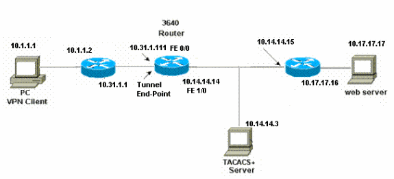
This configuration is designed to bring up the web browser on 10.1.1.1 and aim it at 10.17.17.17. Because the VPN Client is configured to go through tunnel end-point 10.31.1.111 to get to the 10.17.17.x network, the IPSec tunnel is built and the PC gets the IP address out of the pool RTP-POOL (since mode-configuration is performed). Authentication is then requested by the Cisco 3640 Router. After the user enters a username and password (stored on the TACACS+ server at 10.14.14.3), the access list passed down from the server gets added to access list 118.
Prerequisites
Requirements
Before attempting this configuration, ensure that you meet these requirements:
-
Cisco VPN Client is configured to establish an IPSec tunnel with the Cisco 3640 Router.
-
The TACACS+ server is configured for authentication proxy. See the "Related Information" section for more information.
Components Used
The information in this document is based on these software and hardware versions:
-
Cisco IOS? Software Release 12.4
-
Cisco 3640 Router
-
Cisco VPN Client for Windows version 4.8 (any VPN Client 4.x and later should work)
Note: The ip auth-proxy command was introduced in Cisco IOS Software Release 12.0.5.T. This configuration was tested with Cisco IOS Software Release 12.4.
The information in this document was created from the devices in a specific lab environment. All of the devices used in this document started with a cleared (default) configuration. If your network is live, make sure that you understand the potential impact of any command.
Conventions
For more information on document conventions, refer to the Cisco Technical Tips Conventions.
Configure
In this section, you are presented with the information to configure the features described in this document.
Note: To find additional information on the commands used in this document, use the Command Lookup Tool (registered customers only) .
Network Diagram
This document uses this network setup:
Configuration
| 3640 Router |
|---|
Current configuration: ! version 12.4 service timestamps debug uptime service timestamps log uptime no service password-encryption ! hostname 3640 ! !--- The username and password is used during local authentication. username rtpuser password 0 rtpuserpass !--- Enable AAA. aaa new-model !--- Define server-group and servers for TACACS+. aaa group server tacacs+ RTP server 10.14.14.3 ! !--- In order to set authentication, authorization, and accounting (AAA) authentication at login, use the aaa authentication login command in global configuration mode aaa authentication login default group RTP local aaa authentication login userauth local aaa authorization exec default group RTP none aaa authorization network groupauth local aaa authorization auth-proxy default group RTP enable secret 5 $1$CQHC$R/07uQ44E2JgVuCsOUWdG1 enable password ww ! ip subnet-zero ! !--- Define auth-proxy banner, timeout, and rules. ip auth-proxy auth-proxy-banner http ^C Please Enter Your Username and Password: ^C ip auth-proxy auth-cache-time 10 ip auth-proxy name list_a http ip audit notify log ip audit po max-events 100 cns event-service server ! !--- Define ISAKMP policy. crypto isakmp policy 10 hash md5 authentication pre-share group 2 !--- These commands define the group policy that !--- is enforced for the users in the group RTPUSERS. !--- This group name and the key should match what !--- is configured on the VPN Client. The users from this !--- group are assigned IP addresses from the pool RTP-POOL. crypto isakmp client configuration group RTPUSERS key cisco123 pool RTP-POOL ! !--- Define IPSec transform set and apply it to the dynamic crypto map. crypto ipsec transform-set RTP-TRANSFORM esp-des esp-md5-hmac ! crypto dynamic-map RTP-DYNAMIC 10 set transform-set RTP-TRANSFORM ! !--- Define extended authentication (X-Auth) using the local database. !--- This is to authenticate the users before they can !--- use the IPSec tunnel to access the resources. crypto map RTPCLIENT client authentication list userauth !--- Define authorization using the local database. !--- This is required to push the 'mode configurations' to the VPN Client. crypto map RTPCLIENT isakmp authorization list groupauth crypto map RTPCLIENT client configuration address initiate crypto map RTPCLIENT client configuration address respond crypto map RTPCLIENT 10 ipsec-isakmp dynamic RTP-DYNAMIC ! interface FastEthernet0/0 ip address 10.31.1.111 255.255.255.0 ip access-group 118 in no ip directed-broadcast !--- Apply the authentication-proxy rule to the interface. ip auth-proxy list_a no ip route-cache no ip mroute-cache speed auto half-duplex !--- Apply the crypto-map to the interface. crypto map RTPCLIENT ! interface FastEthernet1/0 ip address 10.14.14.14 255.255.255.0 no ip directed-broadcast speed auto half-duplex ! !--- Define the range of addresses in the pool. !--- VPN Clients will have thier 'internal addresses' assigned !--- from this pool. ip local pool RTP-POOL 10.20.20.25 10.20.20.50 ip classless ip route 0.0.0.0 0.0.0.0 10.14.14.15 ip route 10.1.1.0 255.255.255.0 10.31.1.1 !--- Turn on the HTTP server and authentication. !--- This is required for http auth-proxy to work. ip http server ip http authentication aaa ! !--- The access-list 118 permits ISAKMP and IPSec packets !--- to enable the Cisco VPN Client to establish the IPSec tunnel. !--- The last line of the access-list 118 permits communication !--- between the TACACS+ server and the 3640 router to enable !--- authentication and authorization. All other traffic is denied. access-list 118 permit esp 10.1.1.0 0.0.0.255 host 10.31.1.111 access-list 118 permit udp 10.1.1.0 0.0.0.255 host 10.31.1.111 eq isakmp access-list 118 permit tcp host 10.14.14.3 host 10.31.1.111 ! !--- Define the IP address and the key for the TACACS+ server. tacacs-server host 10.14.14.3 key cisco ! line con 0 transport input none line aux 0 line vty 0 4 password ww ! end |
VPN Client 4.8 Configuration
Complete these steps in order to configure the VPN Client 4.8:
-
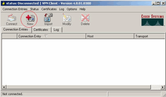
Choose Start > Programs > Cisco Systems VPN Client > VPN Client.
-
Click New to launch the Create New VPN Connection Entry window.
-
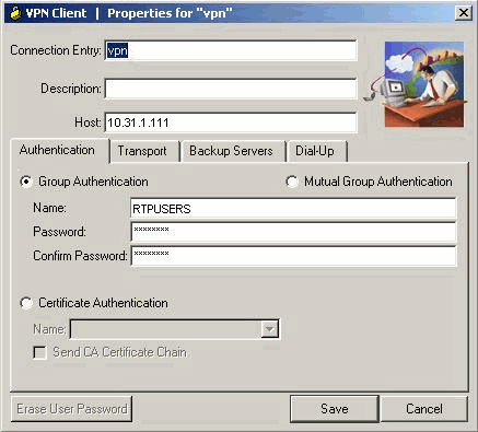
Enter the name of the Connection Entry along with a description. Enter the outside IP address of the router in the Host box. Then enter the VPN Group name and password, and click Save.
-
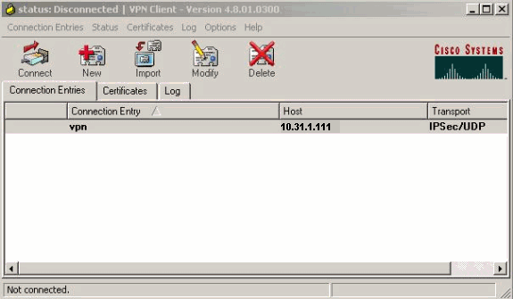
Click on the connection you would like to use and click Connect from the VPN Client main window.
-
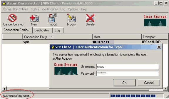
When prompted, enter the Username and Password information for xauth and click OK to connect to the remote network.
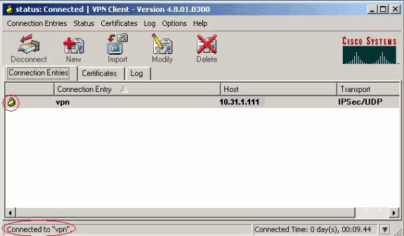
The VPN Client gets connected with the router at the central site.
Configure the TACACS+ Server Using Cisco Secure ACS
Complete these steps in order to configure TACACS+ in a Cisco Secure ACS:
-
You must configure the router to locate the Cisco Secure ACS in order to check the user credentials.
For example:
3640(config)#
aaa group server tacacs+ RTP

3640(config)#
tacacs-server host 10.14.14.3 key cisco
-
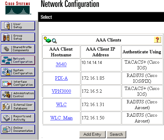
Choose Network Configuration on the left and click Add Entry to add an entry for the router in either the TACACS+ server database. Choose the server database according to the router configuration.
-
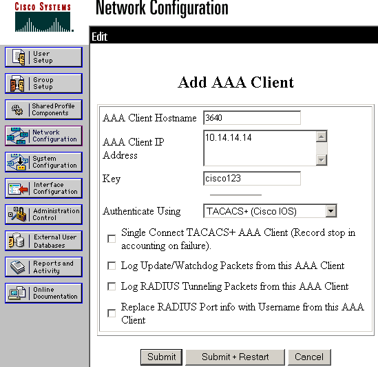
The key is used to authenticate between the 3640 Router and Cisco Secure ACS server. If you want to select the TACACS+ protocol for authentication, then choose TACACS+ (Cisco IOS) in the Authenticate Using drop down menu.
-
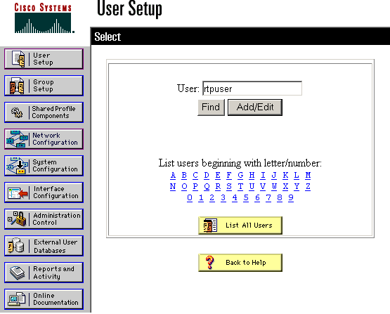
Enter the username in the User field in the Cisco Secure database, then click Add/Edit.
In this example, the username is rtpuser.
-
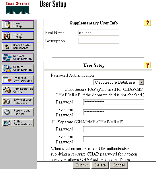
In the next window, enter the password for rtpuser.
In this example, the password is rtpuserpass. You can map the user account to a group if you wish. When you have finished, click Submit.
Configure the Fallback Feature
When the primary RADIUS server becomes unavailable, the router will failover to the next active backup RADIUS server. The router will continue to use the secondary RADIUS server forever even if the primary server is available. Usually the primary server is high performance and the preferred server. If the secondary server is not available the local database can be used for authentication using the aaa authentication login default group RTP local command.
Verify
This section provides information you can use to confirm your configuration is working properly.
Establish an IPSec tunnel between the PC and the Cisco 3640 Router.
Open a browser on the PC and point it to http://10.17.17.17. The Cisco 3640 Router intercepts this HTTP traffic, triggers authentication proxy, and prompts you for a username and password. The Cisco 3640 sends the username/password to the TACACS+ server for authentication. If the authentication is successful, you should be able to see the web pages on the Web server at 10.17.17.17.
Certain show commands are supported by the Output Interpreter Tool (registered customers only) , which allows you to view an analysis of show command output.
-
show ip access-lists —Displays the standard and extended ACLs configured on the firewall router (includes dynamic ACL entries). The dynamic ACL entries are added and removed periodically based on whether the user authenticates or not.
This output shows acess-list 118 before auth-proxy was triggered:
3640#show ip access-lists 118
   Extended IP access list 118
   10 permit esp 10.1.1.0 0.0.0.255 host 10.31.1.111 (321 matches)
   20 permit udp 10.1.1.0 0.0.0.255 host 10.31.1.111 eq isakmp (276 matches)
   30 permit tcp host 10.14.14.3 host 10.31.1.111 (174 matches)
This output shows access-list 118 after auth-proxy was triggered and the user successfully authenticates:
3640#show ip access-lists 118
   Extended IP access list 118
   permit tcp host 10.20.20.26 any (7 matches)
   permit udp host 10.20.20.26 any (14 matches)
   permit icmp host 10.20.20.26 any
   10 permit esp 10.1.1.0 0.0.0.255 host 10.31.1.111 (379 matches)
   20 permit udp 10.1.1.0 0.0.0.255 host 10.31.1.111 eq isakmp (316 matches)
   30 permit tcp host 10.14.14.3 host 10.31.1.111 (234 matches)
The first three lines of the access-list are the entries defined for this user and downloaded from the TACACS+ server.
-
show ip auth-proxy cache —Displays either the authentication proxy entries or the running authentication proxy configuration. The cache keyword to list the host IP address, the source port number, the timeout value for the authentication proxy, and the state for connections that use authentication proxy. If the authentication proxy state is ESTAB, the user authentication is a success.
3640#show ip auth-proxy cache
   Authentication Proxy Cache
   Client IP 10.20.20.26 Port 1705, timeout 5, state ESTAB
Troubleshoot
For the verification and debugging commands, along with other troubleshooting information, refer to Troubleshooting Authentication Proxy.
Note: Before issuing debug commands, refer to Important Information on Debug Commands.
Related Information
- Configuring Authentication Proxy
- Authentication Proxy Configurations in Cisco IOS
- Implementing Authentication Proxy in TACACS+ and RADIUS Servers
- Cisco VPN Client Support Page
- IOS Firewall Support Page
- IPSec Support Page
- RADIUS Support Page
- Requests for Comments (RFCs)
- TACACS/TACACS+ Support Page
- TACACS+ in IOS Documentation
- Technical Support - Cisco Systems
Contact Cisco
- Open a Support Case

- (Requires a Cisco Service Contract)
 Feedback