LAN-to-LAN IPsec Tunnel Between a Cisco VPN 3000 Concentrator and Router with AES Configuration Example
Available Languages
Contents
Introduction
This document shows how to configure an IPsec tunnel between a Cisco VPN 3000 Concentrator and a Cisco router with Advance Encryption Standard (AES) as the encryption algorithm.
AES is a new Federal Information Processing Standard (FIPS) publication created by the National Institute of Standards and Technology (NIST) to be used as an encryption method. This standard specifies an AES symmetric encryption algorithm that replaces the Data Encryption Standard (DES) as a privacy transform for both IPsec and Internet Key Exchange (IKE). AES has three different key lengths, a 128-bit key (the default), a 192-bit key, and a 256-bit key. The AES feature in Cisco IOS® adds support for the new encryption standard AES, with Cipher Block Chaining (CBC) Mode, to IPsec.
Refer to the NIST Computer Security Resource Center site ![]() for more information on AES.
for more information on AES.
Refer to LAN-to-LAN IPsec Tunnel Between the Cisco VPN 3000 Concentrator and PIX Firewall Configuration Example for more information about the LAN-to-LAN tunnel configuration between a VPN 3000 Concentrator and PIX Firewall.
Refer to IPsec Tunnel Between PIX 7.x and VPN 3000 Concentrator Configuration Example for more information when the PIX has software version 7.1.
Prerequisites
Requirements
This document requires a basic understanding of IPsec protocol. Refer to An Introduction to IPSec Encryption to learn more about IPsec.
Ensure that you meet these requirements before you attempt this configuration:
-
Router Requirements - The AES feature was introduced in Cisco IOS Software Release 12.2(13)T. In order to enable AES, your router must support IPsec and run an IOS image with "k9" long keys (the "k9" subsystem).
Note: Hardware support for AES is also available on Cisco 2600XM, 2691, 3725, and 3745 AES acceleration VPN modules. This feature has no configuration implications and the hardware module is automatically selected if both are available.
-
VPN Concentrator Requirements - The software support for the AES feature was introduced in release 3.6. Hardware support is provided by the new enhanced, scalable encryption processor (SEP-E). This feature has no configuration implications.
Note: In Cisco VPN 3000 Concentrator release 3.6.3, tunnels do not negotiate to AES due to Cisco bug ID CSCdy88797 (registered customers only) . This has been resolved from release 3.6.4.
Note: The Cisco VPN 3000 Concentrator uses either SEP or SEP-E modules, not both. Do not install both on the same device. If you install an SEP-E module on a VPN Concentrator that already contains an SEP module, the VPN Concentrator disables the SEP module and uses only the SEP-E module.
Components Used
The information in this document is based on the software and hardware versions:
-
Cisco 3600 Series Router with Cisco IOS Software Release 12.3(5)
-
Cisco VPN 3060 Concentrator with Software Release 4.0.3
The information in this document was created from the devices in a specific lab environment. All of the devices used in this document started with a cleared (default) configuration. If your network is live, make sure that you understand the potential impact of any command.
Conventions
Refer to the Cisco Technical Tips Conventions for more information on document conventions.
Configure
In this section, you are presented with the information to configure the features described in this document.
Note: Use the Command Lookup Tool (registered customers only) to obtain more information on the commands used in this section.
Network Diagram
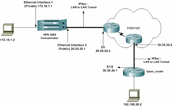
This document uses this network setup:
Configurations
This document uses these configurations:
| ipsec_router Configuration |
|---|
version 12.3 service timestamps debug uptime service timestamps log datetime msec no service password-encryption ! hostname ipsec_router ! memory-size iomem 10 no aaa new-model ip subnet-zero ! !--- Configuration for IKE policies. crypto isakmp policy 1 !--- Enables the IKE policy configuration (config-isakmp) command mode, !--- where you can specify the parameters to be used during !--- an IKE negotiation. encryption aes 256 !--- Specifies the encryption algorithm as AES with a 256 !--- bit key within an IKE policy. authentication pre-share group 2 crypto isakmp key cisco123 address 20.20.20.1 !--- Specifies the preshared key "cisco123" which !--- should be identical at both peers. ! !--- Configuration for IPsec policies. crypto ipsec security-association lifetime seconds 28800 !--- Specifies the lifetime of the IPsec security association (SA). ! crypto ipsec transform-set vpn esp-aes 256 esp-md5-hmac !--- Enables the crypto transform configuration mode, where you can !--- specify the transform sets to be used during an IPsec negotiation. ! crypto map vpn 10 ipsec-isakmp !--- Indicates that IKE is used to establish the IPsec SA for protecting !--- the traffic specified by this crypto map entry. set peer 20.20.20.1 !--- Sets the IP address of the remote end (VPN Concentrator). set transform-set vpn !--- Configures IPsec to use the transform-set "vpn" defined earlier. ! !--- Specifies the traffic to be encrypted. match address 110 ! interface Ethernet1/0 ip address 30.30.30.1 255.255.255.0 ip nat outside half-duplex crypto map vpn !--- Configures the interface to use the crypto map "vpn" for IPsec. ! interface FastEthernet2/0 ip address 192.168.20.1 255.255.255.0 ip nat inside duplex auto speed auto ! ip nat pool mypool 30.30.30.3 30.30.30.3 netmask 255.255.255.0 ip nat inside source route-map nonat pool mypool overload ip http server no ip http secure-server ip classless ip route 0.0.0.0 0.0.0.0 30.30.30.2 ! access-list 110 permit ip 192.168.20.0 0.0.0.255 172.16.0.0 0.0.255.255 !--- This crypto ACL-permit identifies the matching traffic !--- flows to be protected via encryption. !--- Specifies the traffic not to be encrypted. access-list 120 deny ip 192.168.20.0 0.0.0.255 172.16.0.0 0.0.255.255 !--- This crypto ACL-deny identifies the matching traffic flows not to be encrypted. ! access-list 120 permit ip 192.168.20.0 0.0.0.255 any !--- The access control list (ACL) used in the NAT configuration exempts !--- the LAN-to-LAN traffic from the NAT process, !--- but allows all traffic going to the Internet to be translated. ! route-map nonat permit 10 !--- The traffic flows not encrypted from the !--- peer network are allowed. match ip address 120 ! line con 0 line aux 0 line vty 0 4 login ! end |
Note: Although the ACL syntax is unchanged, the meanings are slightly different for crypto ACLs. In crypto ACLs, permit specifies that matching packets should be encrypted, whereas deny specifies that matching packets do not need to be encrypted.
Configure the VPN Concentrator
VPN Concentrators are not pre-programmed with IP addresses in their factory settings. You have to use the console port to configure the initial configurations which are a menu-based command-line interface (CLI). Refer to Configuring VPN Concentrators through the Console for information on how to configure through the console.
After the IP address on the Ethernet 1 (private) interface is configured, the rest can be configured either using the CLI or via the browser interface. The browser interface supports both HTTP and HTTP over Secure Socket Layer (SSL).
These parameters are configured through the console:
-
Time/Date - The correct time and date are very important. They help ensure that logging and accounting entries are accurate, and that the system can create a valid security certificate.
-
Ethernet 1 (private) interface - The IP address and mask (from our network topology 172.16.1.1/24).
At this point, the VPN Concentrator is accessible through an HTML browser from the inside network. For information on configuring the VPN Concentrator in CLI mode, refer to Quick Configuration using CLI.
-
Type the IP address of the private interface from the web browser to enable the GUI interface.
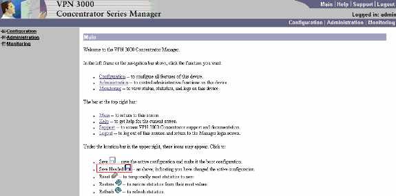
Click on the save needed icon to save changes to memory. The factory default username and password are "admin" which is case sensitive.
-
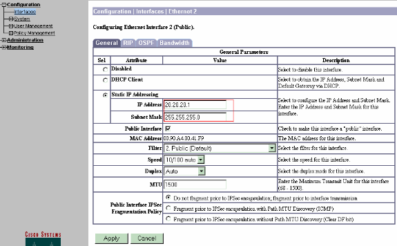
After you bring up the GUI, select Configuration > Interfaces > Ethernet 2 (Public) to configure the Ethernet 2 interface.
-
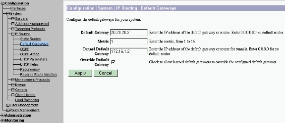
Select Configuration > System > IP Routing > Default Gateways configure the default (Internet) gateway and the tunnel default (inside) gateway for IPsec to reach the other subnets in the private network.
In this scenario, there is only one subnet available on the inside network.
-
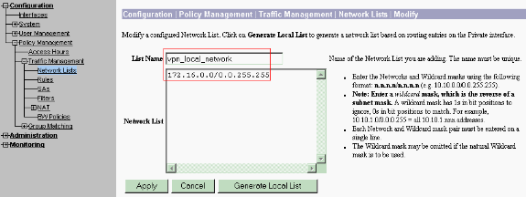
Select Configuration > Policy Management > Traffic Management > Network Lists > Add to create the network lists defining the traffic to be encrypted.
The networks mentioned in the list are reachable to the remote network. The networks shown in the list below are Local networks. You can also generate the Local network list automatically via RIP when you click Generate Local List.
-
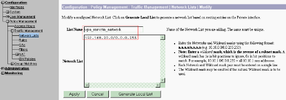
The networks in this list are remote networks and need to be manually configured. In order to do this, enter the network/wildcard for each reachable subnet.
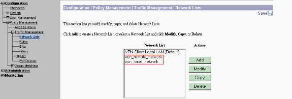
When completed, these are the two network lists:
-
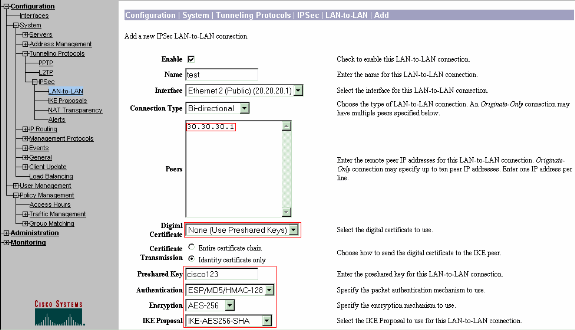
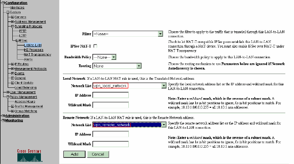
Select Configuration > System > Tunneling Protocols > IPSec LAN-to-LAN > Add and define the LAN-to-LAN tunnel.
This window has three sections. The top section is for the network information and the bottom two sections are for the Local and Remote network lists. In the Network Information section, select the AES encryption, authentication type, IKE proposal, and type the pre-shared key. In the bottom sections, point to the Network lists that you already created, both Local and Remote lists respectively.
-
After you click Add, if your connection is correct, you are presented with the IPSec LAN-to-LAN-Add-Done window.
This window presents a synopsis of the tunnel configuration information. It also automatically configures the Group Name, SA Name, and the Filter Name. You can edit any parameters in this table.
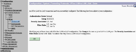
At this point the IPsec LAN-to-LAN tunnel has been set up and you can start working. If, for some reason, the tunnel does not work, you can check for misconfigurations.
-
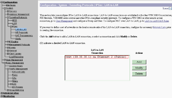
You can view or modify the previously created LAN-to-LAN IPsec parameters when you select Configuration > System > Tunneling Protocols > IPSec LAN-to-LAN.
This graphic shows "test" as the name of the tunnel and the public interface of the remote end is 30.30.30.1 as per the scenario.
-
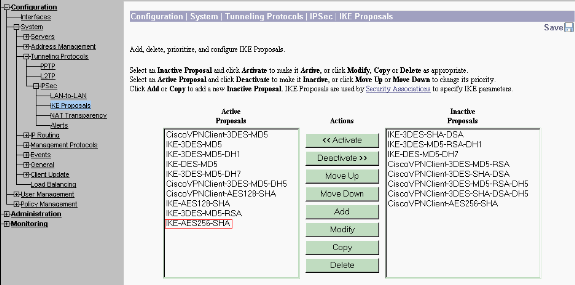
At times, your tunnel might not come up if your IKE proposal is in the Inactive Proposals list. Select Configuration > System > Tunneling Protocols > IPSec > IKE Proposals to configure the active IKE proposal.
If your IKE proposal is in the "Inactive Proposals" list you can enable it when you select the IKE proposal and click on the Activate button. In this graphic the selected proposal "IKE-AES256-SHA" is in the Active proposals list.
-
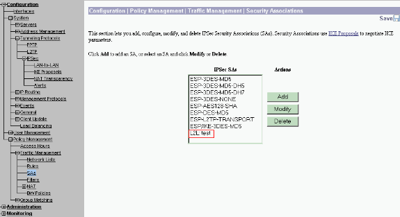
Select Configuration > Policy Management > Traffic Management > Security Associations to verify if the SA parameters are correct.
-
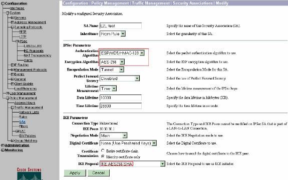
Click the SA name (in this case, L2L: test), and then click Modify to verify the SAs.
If any of the parameters do not match with the remote peer configuration, it can be changed here.
Verify
Verify the Router Configuration
This section provides information you can use to confirm your configuration works properly.
Certain show commands are supported by the Output Interpreter Tool (registered customers only) , which allows you to view an analysis of show command output.
-
show crypto isakmp sa—Displays all current IKE SAs at a peer. The state QM_IDLE denotes that the SA remains authenticated with its peer and can be used for subsequent quick mode exchanges. It is in a quiescent state.
ipsec_router#show crypto isakmp sa

 dst            src           state    conn-id   slot

 20.20.20.1     30.30.30.1    QM_IDLE        1      0
-
show crypto ipsec sa —Displays the settings used by current SAs. Check for the peer IP addresses, the networks accessible at both the local and remote ends, and the transform set that is used. There are two ESP SAs, one in each direction. Since AH transform sets are used, it is empty.
ipsec_router#show crypto ipsec sa interface: Ethernet1/0 Crypto map tag: vpn, local addr. 30.30.30.1 protected vrf: local ident (addr/mask/prot/port): (192.168.20.0/255.255.255.0/0/0) remote ident (addr/mask/prot/port): (172.16.0.0/255.255.0.0/0/0) current_peer: 20.20.20.1:500 PERMIT, flags={origin_is_acl,} #pkts encaps: 145, #pkts encrypt: 145, #pkts digest 145 #pkts decaps: 51, #pkts decrypt: 51, #pkts verify 51 #pkts compressed: 0, #pkts decompressed: 0 #pkts not compressed: 0, #pkts compr. failed: 0 #pkts not decompressed: 0, #pkts decompress failed: 0 #send errors 6, #recv errors 0 local crypto endpt.: 30.30.30.1, remote crypto endpt.: 20.20.20.1 path mtu 1500, media mtu 1500 current outbound spi: 54FA9805 inbound esp sas: spi: 0x4091292(67703442) transform: esp-256-aes esp-md5-hmac , in use settings ={Tunnel, } slot: 0, conn id: 2000, flow_id: 1, crypto map: vpn sa timing: remaining key lifetime (k/sec): (4471883/28110) IV size: 16 bytes replay detection support: Y inbound ah sas: inbound pcp sas: outbound esp sas: spi: 0x54FA9805(1425709061) transform: esp-256-aes esp-md5-hmac , in use settings ={Tunnel, } slot: 0, conn id: 2001, flow_id: 2, crypto map: vpn sa timing: remaining key lifetime (k/sec): (4471883/28110) IV size: 16 bytes replay detection support: Y outbound ah sas: outbound pcp sas: -
show crypto engine connections active—Displays the current active encrypted session connections for all crypto engines. Each connection ID is unique. The number of packets that are encrypted and decrypted are displayed in the last two columns.
ipsec_router#show crypto engine connections active
   ID     Interface     IP-Address   State   Algorithm          Encrypt Decrypt

    1     Ethernet1/0   30.30.30.1   set     HMAC_SHA+AES_256_C       0       0

 2000     Ethernet1/0   30.30.30.1   set     HMAC_MD5+AES_256_C       0      19

 2001     Ethernet1/0   30.30.30.1   set     HMAC_MD5+AES_256_C      19       0
Verify the VPN Concentrator Configuration
Complete these steps to verify the VPN Concentrator configuration.
-
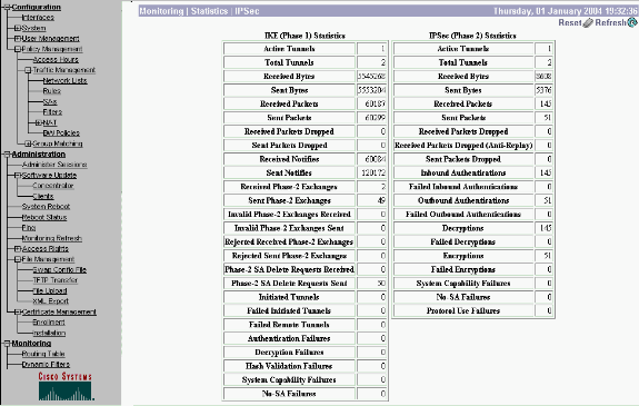
Similar to show crypto ipsec sa and show crypto isakmp sa commands on routers, you can view the IPsec and IKE statistics when you select Monitoring > Statistics > IPSec on the VPN Concentrators.
-
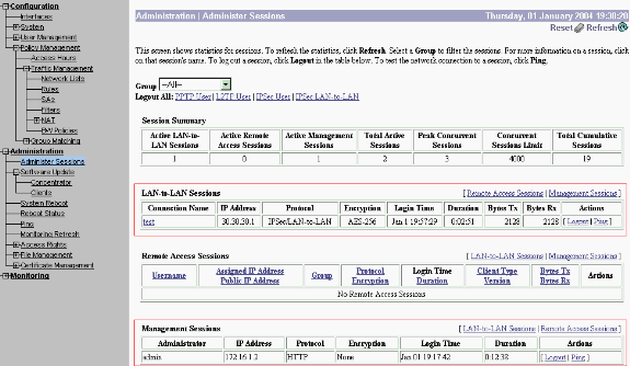
Similar to the show crypto engine connections active command on routers, you can use the Administration-Sessions window on the VPN Concentrator to view the parameters and statistics for all active IPsec LAN-to-LAN connections or tunnels.
Troubleshoot
This section provides information you can use to troubleshoot your configuration.
Troubleshoot the Router
The Output Interpreter Tool (registered customers only) (OIT) supports certain show commands. Use the OIT to view an analysis of show command output.
Note: Refer to Important Information on Debug Commands before you use debug commands.
-
debug crypto engine—Displays the traffic that is encrypted. The crypto engine is the actual mechanism that performs encryption and decryption. A crypto engine can be a software or a hardware accelerator.
-
debug crypto isakmp—Displays the Internet Security Association and Key Management Protocol (ISAKMP) negotiations of IKE phase 1.
-
debug crypto ipsec—Displays the IPsec negotiations of IKE phase 2.
Refer to IPSec Troubleshooting - Understanding and Using debug Commands for more detailed information and sample output.
Troubleshoot the VPN Concentrator
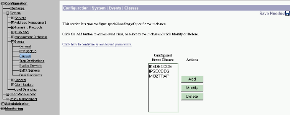
Similar to debug commands on the Cisco routers, you can configure Event classes to view all alarms.
-
Select Configuration > System > Events > Classes > Add to turn on logging of Event classes.
These classes are available for IPsec:
-
IKE
-
IKEDBG
-
IKEDECODE
-
IPSEC
-
IPSECDBG
-
IPSECDECODE
-
-
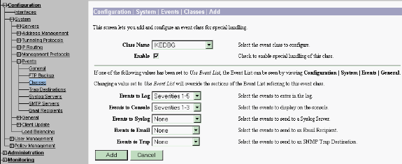
While adding, you can also select the Severity level for each class, based on the Severity level that the alarm is sent.
The alarms can be handled by one of these methods:
-
By log
-
Displayed on the Console
-
Sent to the UNIX Syslog server
-
Sent as an email
-
Sent as a trap to a Simple Network Management Protocol (SNMP) server
-
-
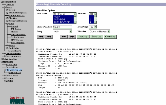
Select Monitoring > Filterable Event Log to monitor the enabled alarms.
Related Information
Revision History
| Revision | Publish Date | Comments |
|---|---|---|
1.0 |
16-Aug-2002 |
Initial Release |
Contact Cisco
- Open a Support Case

- (Requires a Cisco Service Contract)


 Feedback