Configuring Redundant Routing on the VPN 3000 Concentrator
Available Languages
Contents
Introduction
This document describes how to configure a redundant VPN failover if a remote site loses its VPN 3000 Concentrator or Internet connectivity. In this example, assume that the corporate network located behind the VPN 3030B uses Open Shortest Path First (OSPF) as its default routing protocol.
Note: When you redistribute between routing protocols, you can form a routing loop which can cause trouble on the network. OSPF is used in this example, but it is not the only routing protocol that can be used.
The goal of this example is to have the 192.168.1.0 network use the red tunnel (under normal operating circumstances), depicted in the Network Diagram section, to reach 192.168.3.x. If the tunnel, VPN Concentrator, or ISP drops, then the192.168.3.0 network is learned over a dynamic routing protocol over the green tunnel. Also, connectivity is not lost to the 192.168.3.0 site. Once the issue is resolved, the traffic automatically reverts back to the red tunnel.
Note: RIP has a three minute aging timer before it allows a new route to be accepted over an invalid route. Also, assume that the tunnels are created and that traffic can pass among the peers.
Prerequisites
Requirements
There are no specific requirements for this document.
Components Used
The information in this document is based on these software and hardware versions:
-
Cisco Routers 3620 and 3640
-
Cisco VPN 3080 Concentrator - Version: Cisco Systems, Inc./VPN 3000 Concentrator Version 4.7
-
Cisco VPN 3060 Concentrator - Version: Cisco Systems, Inc./VPN 3000 Concentrator Series Version 4.7
-
Cisco VPN 3030 Concentrator - Version: Cisco Systems, Inc./VPN 3000 Concentrator Series Version 4.7
The information in this document was created from the devices in a specific lab environment. All of the devices used in this document started with a cleared (default) configuration. If your network is live, make sure that you understand the potential impact of any command.
Conventions
For more information on document conventions, refer to the Cisco Technical Tips Conventions.
Configure
In this section, you are presented with the information to configure the features described in this document.
Note: To find additional information on the commands used in this document, use the Command Lookup Tool (registered customers only) .
Network Diagram
This document uses this network setup:
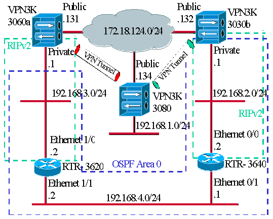
The blue dashes indicate that OSPF is enabled from VPN 3030b to RTR-3640 and RTR-3620.
The green dashes indicate that RIPv2 is enabled from private VPN 3060a to RTR-3620, RTR-3640, and private VPN 3030b.
RIPv2 is also enabled on the red and green VPN tunnels because network discovery is enabled. It is not necessary to enable RIP on the VPN 3080 private interface. There is also no RIP on the 192.168.4.x network because all routes are learned by OSPF over this link.
Note: PCs on the 192.168.2.x and 192.168.3.x networks need to have their default gateways pointing to the routers and not to the VPN Concentrators. Allow the routers to decide on where to route the packets.
Router Configurations
This document uses these router configurations:
| Router 3620 |
|---|
rtr-3620#write terminal Building configuration... Current configuration : 873 bytes ! version 12.2 service timestamps debug uptime service timestamps log uptime no service password-encryption ! hostname rtr-3620 ! ip subnet-zero ! interface Ethernet1/0 ip address 192.168.3.2 255.255.255.0 half-duplex ! interface Ethernet1/1 ip address 192.168.4.2 255.255.255.0 half-duplex ! router ospf 1 log-adjacency-changes !--- To pass the routes learned through RIP into the OSPF process, !--- use the redistribute command. !--- To prevent a routing loop, block the 192.168.1.0 network !--- from entering the OSPF process. It should only be learned !--- through the RIP process. No two different routing processes !--- exchange information unless you implicitly use the !--- redistribute command. !--- The 192.168.1.x network is learned through OSPF from the !--- 192.168.2.x side. However, since the admin distance is changed, !--- it is not installed into the table !--- because RIP has an administrative distance of 120, !--- and all of the OSPF distances are 130. redistribute rip subnets route-map block192.168.1.0 !--- To enable the OSPF process for the interfaces that are included !--- in the 192.168.x.x networks: network 192.168.0.0 0.0.255.255 area 0 !--- Since RIP's default admin distance is 120 and OSPF's is 110, !--- make RIP a preferable metric for communications !--- over the "backup" network. !--- Change any learned OSPF routes from neighbor 192.168.4.1 !--- to an admin distance of 130. distance 130 192.168.4.1 0.0.0.0 ! !--- To enable RIP on the Ethernet 1/0 interface and set it to !--- use version 2: router rip version 2 network 192.168.3.0 ! ip classless ! ! access-list 1 deny 192.168.1.0 0.0.0.255 access-list 1 permit any route-map block192.168.1.0 permit 10 match ip address 1 ! line con 0 exec-timeout 0 0 line aux 0 line vty 0 4 ! end |
| Router 3640 |
|---|
rtr-3640#write terminal Building configuration... Current configuration : 1129 bytes ! version 12.2 service timestamps debug uptime service timestamps log uptime no service password-encryption ! hostname rtr-3640 ! ip subnet-zero ! interface Ethernet0/0 ip address 192.168.2.2 255.255.255.0 half-duplex ! interface Ethernet0/1 ip address 192.168.4.1 255.255.255.0 half-duplex ! router ospf 1 log-adjacency-changes !--- Use this command to push RIP learned routes into OSPF. !--- You need this when the VPN 3060a or the connection drops and !--- the 192.168.3.0 route needs to be injected into the OSPF backbone. redistribute rip subnets !--- Place all 192.168.x.x networks into area 0. network 192.168.0.0 0.0.255.255 area 0 !--- Since RIP's default admin distance is 120 and OSPF's is 110, !--- make RIP a preferable metric for communications !--- over the "backup" network. !--- Change any learned OSPF routes from neighbor 192.168.4.2 !--- to an admin distance of 130. distance 130 192.168.4.2 0.0.0.0 ! !--- To enable RIP on the Ethernet 0/0 interface and set it to !--- use version 2: router rip version 2 network 192.168.2.0 ! ip classless ! line con 0 exec-timeout 0 0 line aux 0 line vty 0 4 ! end |
VPN 3080 Concentrator Configuration
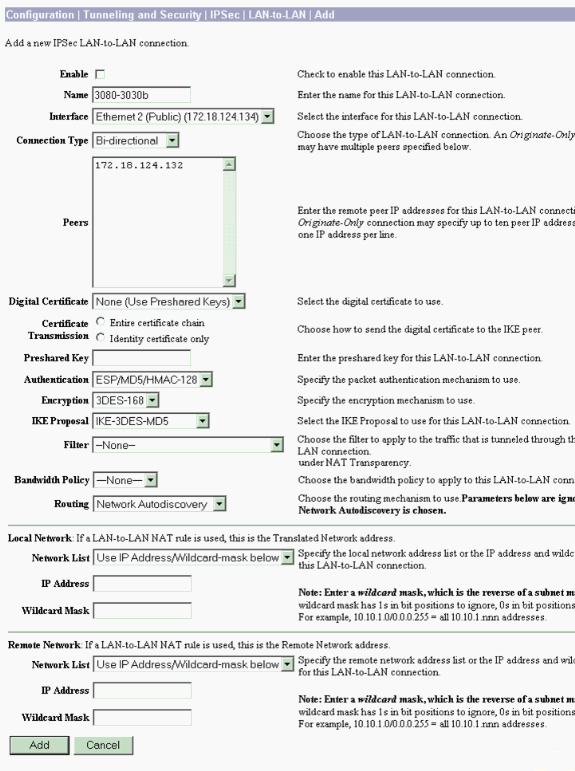
LAN-to-LAN VPN 3080 to VPN 3030b
Select Configuration > Tunneling and Security > IPSec > IPSec LAN-to-LAN. Since Network Autodiscovery is used, there is no need to fill out the local and remote network lists.
Note: VPN Concentrators that run software version 3.1 and earlier have a check box for autodiscovery. Software version 3.5 (used on the VPN 3080) uses a drop-down menu, such as the one pictured here.
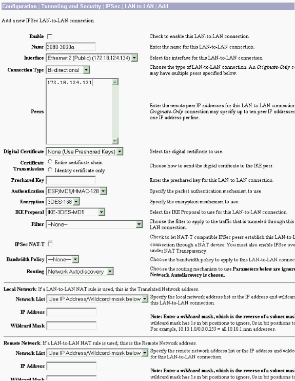
LAN-to-LAN VPN 3080 to VPN 3060a
Select Configuration > Tunneling and Security > IPSec > IPSec LAN-to-LAN. Since Network Autodiscovery is used, there is no need to fill out the local and remote network lists.
Note: VPN Concentrators that run software version 3.1 and earlier have a check box for autodiscovery. Software version 3.5 (used on the VPN 3080) uses a drop-down menu, such as the one pictured here.
VPN 3060a Concentrator Configuration
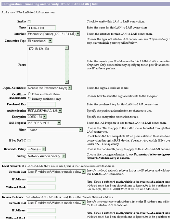
LAN-to-LAN VPN 3060a to VPN 3080
Select Configuration > Tunneling and Security > IPSec > IPSec LAN-to-LAN.
Note: There is a check box on the VPN 3060 for Network Autodiscovery instead of the drop-down menu as in software version 3.5 and later.
Enable RIP to Pass the Tunnel-Learned Routes to the VPN 3620 Router
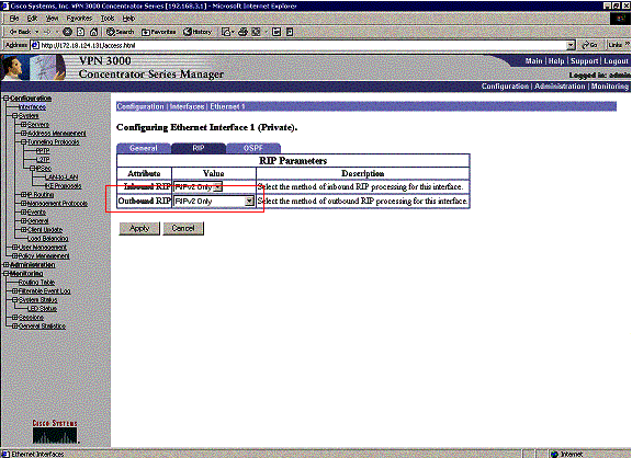
Select Configuration > Interfaces > Private > RIP. Change the drop-down menu to RIPv2 Only and click Apply. Then select Configuration > System > Tunneling Protocols > IPSec > LAN-to-LAN.
Note: The default is outbound RIP, and it is disabled for the private interface.
VPN 3030b Concentrator Configuration
LAN-to-LAN VPN 3030b to VPN 3080
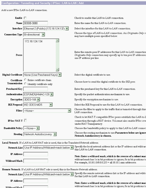
Select Configuration > Tunneling and Security > IPSec > LAN-to-LAN.
Enable RIP to Pass the Tunnel-Learned Routes to the VPN 3640 Router
Follow the steps listed earlier in this document for VPN 3060a Concentrator.
Enable OSPF to Pass the Backbone-Learned Routes to the VPN 3030b Concentrator
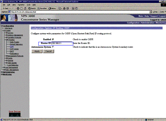
Select Configuration > System > IP Routing > OSPF and enter the router ID.
rtr-3640#show ip ospf neighbor

Neighbor ID     Pri   State           Dead Time   Address         Interface

192.168.4.2       1   FULL/DR         00:00:39    192.168.4.2     Ethernet0/1

!--- For troubleshooting purposes, it helps to make the router ID the !--- IP address of the private interface.

192.168.2.1       1   FULL/BDR        00:00:36    192.168.2.1     Ethernet0/0
The area ID needs to match the ID on the wire. Since the area in this example is 0, it is represented by 0.0.0.0. Also, check the Enable OSPF box and click Apply.
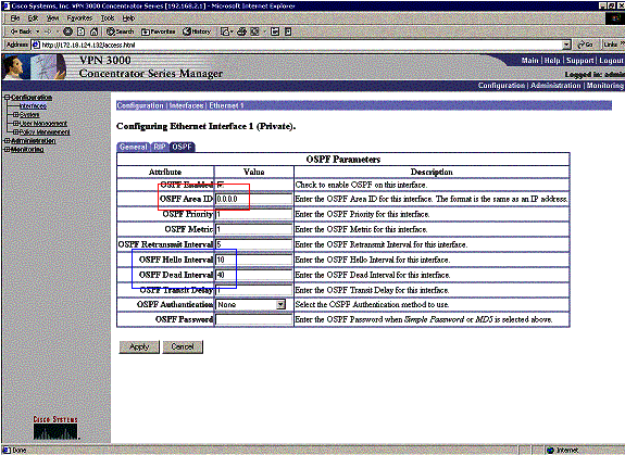
Make sure that your OSPF timers match that of the router. To verify the routers timers, use the show ip ospf interface <interface name> command.
rtr-3640#show ip ospf interface ethernet 0/0
Ethernet0/0 is up, line protocol is up
  Internet Address 192.168.2.2/24, Area 0
  Process ID 1, Router ID 192.168.4.1, Network Type BROADCAST, Cost: 10
  Transmit Delay is 1 sec, State DR, Priority 1
  Designated Router (ID) 192.168.4.1, Interface address 192.168.2.2
  Backup Designated router (ID) 192.168.2.1, Interface address 192.168.2.1
  Timer intervals configured, Hello 10, Dead 40, Wait 40, Retransmit 5
    Hello due in 00:00:05
  Index 1/1, flood queue length 0
  Next 0x0(0)/0x0(0)
  Last flood scan length is 1, maximum is 2
  Last flood scan time is 0 msec, maximum is 0 msec
  Neighbor Count is 1, Adjacent neighbor count is 1
    Adjacent with neighbor 192.168.2.1  (Backup Designated Router)
Suppress hello for 0 neighbor(s)
For more information on OSPF, refer to RFC 1247 ![]() .
.
Verify
This section provides information you can use to confirm your configuration is working properly.
Certain show commands are supported by the Output Interpreter Tool (registered customers only) , which allows you to view an analysis of show command output.
This command output shows accurate routing tables.
rtr-3620#show ip route
Codes: C - connected, S - static, I - IGRP, R - RIP, M - mobile, B - BGP
       D - EIGRP, EX - EIGRP external, O - OSPF, IA - OSPF inter area

Gateway of last resort is not set

     172.18.0.0/24 is subnetted, 1 subnets
R       172.18.124.0 [120/1] via 192.168.3.1, 00:00:11, Ethernet1/0
C    192.168.4.0/24 is directly connected, Ethernet1/1

!--- The 192.168.1.x network is learned from the !--- VPN 3060a Concentrator.

R    192.168.1.0/24 [120/2] via 192.168.3.1, 00:00:11, Ethernet1/0

!--- The 192.168.3.x network traverses the 192.168.4.x network !--- to get to the 192.168.2.x network.

O    192.168.2.0/24 [130/20] via 192.168.4.1, 00:01:07, Ethernet1/1
C    192.168.3.0/24 is directly connected, Ethernet1/0

rtr-3640#show ip route
Codes: C - connected, S - static, I - IGRP, R - RIP, M - mobile, B - BGP
       D - EIGRP, EX - EIGRP external, O - OSPF, IA - OSPF inter area

Gateway of last resort is not set

     172.18.0.0/24 is subnetted, 1 subnets
R       172.18.124.0 [120/1] via 192.168.2.1, 00:00:23, Ethernet0/0
C    192.168.4.0/24 is directly connected, Ethernet0/1

!--- The 192.168.1.x network is learned from the !--- VPN 3030b Concentrator.

R    192.168.1.0/24 [120/2] via 192.168.2.1, 00:00:23, Ethernet0/0
C    192.168.2.0/24 is directly connected, Ethernet0/0

!--- The 192.168.2.x network traverses the 192.168.4.x network !--- to get to the 192.168.3.x network. !--- This is an example of perfect symmetrical routing.

O    192.168.3.0/24 [130/20] via 192.168.4.2, 00:00:58, Ethernet0/1
Thisis the VPN 3080 Concentrator routing table under normal circumstances.
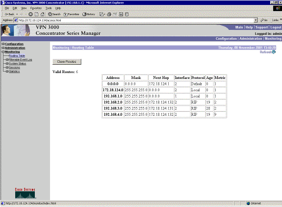
Networks 192.168.2.x and 192.168.3.x are both learned through the VPN tunnels 172.18.124.132 and 172.18.124.131, respectively. The 192.168.4.x network is learned through the 172.18.124.132 tunnel because the router's OSPF advertisements are placed into the VPN 3030b Concentrator's routing table. Then the routing table advertises the network out to the remote VPN peers.
This is the VPN 3030b Concentrator routing table under normal circumstances.
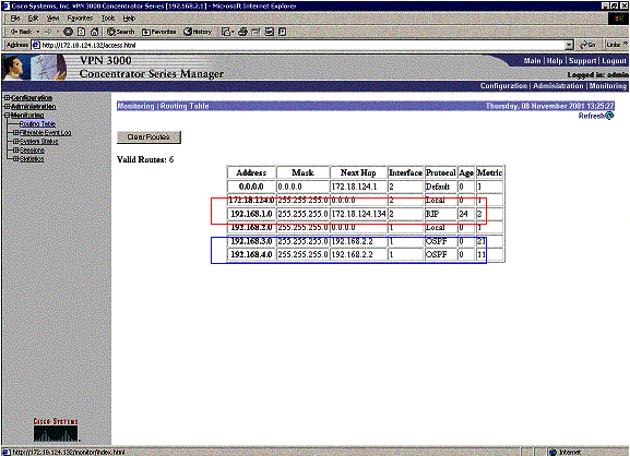
The red box highlights that the 192.168.1.x network is learned from the VPN tunnel. The blue box highlights that networks 192.168.3.x and 192.168.4.x are learned through the core OSPF process.
This is the VPN 3060a Concentrator routing table under normal circumstances.
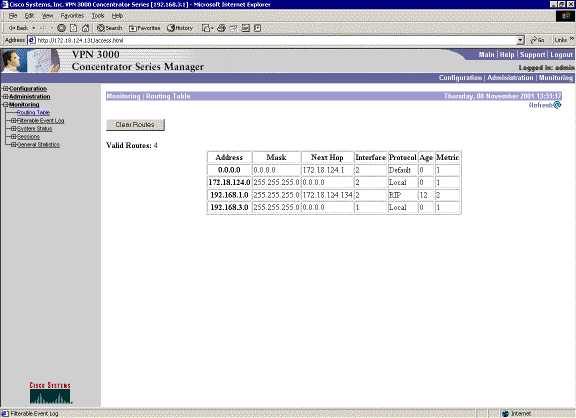
Network 192.168.1.x is the only network here, and it can be reached through the VPN tunnel. There is no 192.168.2.0 network since no process (such as RIP) passes along that route. There is nothing lost as long as the PCs on the 192.168.3.x network do not point their default gateway to the VPN Concentrator. You can always add a static route if you choose. However, for this example, the VPN Concentrator itself does not need to reach the 192.168.2.0 network.
Troubleshoot
Simulated Fault
This is a simulated fault in the configuration. If you remove the filter to the public interface, then the VPN tunnel drops. This causes the route for the 192.168.1.0 learned through the tunnel to drop as well. It takes approximately three minutes for the RIP process to purge out the route. Therefore, you can potentially have a three-minute outage until the route times itself out.
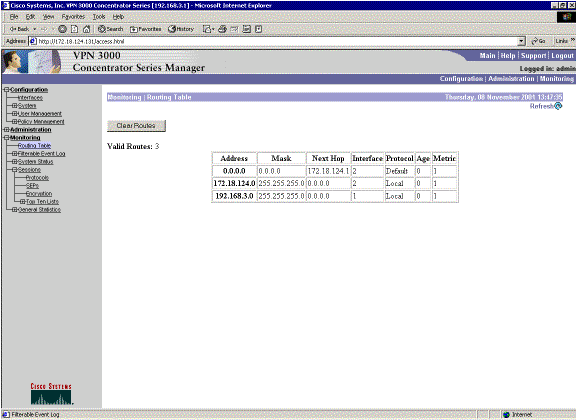
Once the RIP route expires, the new routing table on the routers appears similar to this:
rtr-3620#show ip route

Codes: C - connected, S - static, I - IGRP, R - RIP, M - mobile, B - BGP
       D - EIGRP, EX - EIGRP external, O - OSPF, IA - OSPF inter area
       N1 - OSPF NSSA external type 1, N2 - OSPF NSSA external type 2
       E1 - OSPF external type 1, E2 - OSPF external type 2, E - EGP
       i - IS-IS, L1 - IS-IS level-1, L2 - IS-IS level-2, ia - IS-IS inter area
       * - candidate default, U - per-user static route, o - ODR
       P - periodic downloaded static route

Gateway of last resort is not set

     172.18.0.0/24 is subnetted, 1 subnets
R       172.18.124.0 [120/1] via 192.168.3.1, 00:00:05, Ethernet1/0
C    192.168.4.0/24 is directly connected, Ethernet1/1

!--- Now the 192.168.1.0 route is learned properly !--- through the OSPF backbone.

O E2 192.168.1.0/24 [130/20] via 192.168.4.1, 00:00:05, Ethernet1/1
O    192.168.2.0/24 [130/20] via 192.168.4.1, 19:55:48, Ethernet1/1
C    192.168.3.0/24 is directly connected, Ethernet1/0
What Can Go Wrong?
If you forget to add in the admin distance change to 130, then you can possibly see this output. Note that both VPN tunnels are up.
VPN 3080 Concentrator
Note: This is the non-graphical user interface (GUI) version of the routing table.
Monitor -> 1

Routing Table
-------------

Number of Routes: 6

   IP Address         Mask          Next Hop    Intf Protocol Age Metric
------------------------------------------------------------------------
0.0.0.0         0.0.0.0         172.18.124.1       2 Default    0      1
172.18.124.0    255.255.255.0   0.0.0.0            2 Local      0      1
192.168.1.0     255.255.255.0   0.0.0.0            1 Local      0      1
192.168.2.0     255.255.255.0   172.18.124.132     2 RIP       10      2
192.168.3.0     255.255.255.0   172.18.124.131     2 RIP        2      2
192.168.4.0     255.255.255.0   172.18.124.132     2 RIP       10      9
To get to the 192.168.3.0 network, the route needs to go through 172.18.124.131. However, the routing table on RTR-3620 shows:
rtr-3620#show ip route

Codes: C - connected, S - static, I - IGRP, R - RIP, M - mobile, B - BGP
       D - EIGRP, EX - EIGRP external, O - OSPF, IA - OSPF inter area
       N1 - OSPF NSSA external type 1, N2 - OSPF NSSA external type 2
       E1 - OSPF external type 1, E2 - OSPF external type 2, E - EGP
       i - IS-IS, L1 - IS-IS level-1, L2 - IS-IS level-2, ia - IS-IS inter area
       * - candidate default, U - per-user static route, o - ODR
       P - periodic downloaded static route

Gateway of last resort is not set

     172.18.0.0/24 is subnetted, 1 subnets
O E2    172.18.124.0 [110/20] via 192.168.4.1, 00:03:16, Ethernet1/1
C    192.168.4.0/24 is directly connected, Ethernet1/1

!--- This is an example of asymmetric routing.

O E2 192.168.1.0/24 [110/20] via 192.168.4.1, 00:03:16, Ethernet1/1
O    192.168.2.0/24 [110/20] via 192.168.4.1, 00:03:16, Ethernet1/1
C    192.168.3.0/24 is directly connected, Ethernet1/0
To get back to the 192.168.1.0 network, the route needs to go through the backbone 192.168.4.x network.
The traffic still works since the autodiscovery generates the proper security association (SA) information on the VPN 3030b Concentrator. For example:
Routing -> 1

Routing Table

-------------
Number of Routes: 6
   IP Address         Mask          Next Hop    Intf Protocol Age Metric

------------------------------------------------------------------------
0.0.0.0         0.0.0.0         172.18.124.1       2 Default    0      1
172.18.124.0    255.255.255.0   0.0.0.0            2 Local      0      1
192.168.1.0     255.255.255.0   0.0.0.0            1 Local      0      1
192.168.2.0     255.255.255.0   172.18.124.132     2 RIP       28      2
192.168.3.0     255.255.255.0   172.18.124.131     2 RIP       20      2
192.168.4.0     255.255.255.0   172.18.124.132     2 RIP       28      9
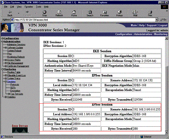
Even though the routing table says the peer should be 172.18.124.131, the actual SA (traffic flow) is through the VPN 3030b Concentrator at 172.18.124.132. The SA table takes precedence over the route table. Only close examination of the route table and the SA table on the VPN 3060a Concentrator shows that traffic does not flow in the right direction.
Related Information
Revision History
| Revision | Publish Date | Comments |
|---|---|---|
1.0 |
10-Dec-2001 |
Initial Release |
Contact Cisco
- Open a Support Case

- (Requires a Cisco Service Contract)
 Feedback