Introduction
This document describes how to configure eBGP using a Loopback interface on the Cisco Secure Firewall.
Prerequisites
Requirements
Cisco recommends that you have knowledge of this topic:
Loopback interface support for BGP was introduced in version 7.4.0, which is the minimum version required for Secure Firewall Management Center and Cisco Secure Firepower Threat Defense.
Components Used
- Secure Firewall Management Center for VMware version 7.4.1
- 2 Cisco Secure Firepower Threat Defense for VMware version 7.4.1
The information in this document was created from the devices in a specific lab environment. All of the devices used in this document started with a cleared (default) configuration. If your network is live, ensure that you understand the potential impact of any command.
Background Information
Border Gateway Protocol (BGP) is an Exterior Gateway Protocol (EGP) standardized path-vector routing protocol that provides scalability, flexibility, and network stability. The BGP session between two peers with the same Autonomous System (AS) is called Internal BGP (iBGP). A BGP session between two peers with different Autonomous Systems (AS) is called External BGP (eBGP).
Typically, the peer relationship is established with the IP address of the interface closest to the peer, however, the use of a Loopback interface to establish the BGP session is useful since it not bring down the BGP session when there are multiple paths between BGP peers.
Note: The process describes the use of a Loopkack for an eBGP peer, however, is the same process for an iBGP peer so it can be used as a reference.
eBGP Configuration with a Loopback Interface
Scenario
In this configuration, Firewall SFTD-1 has a Loopback interface with the IP address 10.1.1.1/32, and the AS 64000, the Firewall SFTD-2 has a Loopback interface with the IP address 10.2.2.2/32 and the AS 64001. Both Firewalls use their outside interface to reach the Loopback interface of the other Firewall (in this scenario, the outside interface is preconfigured on both Firewalls).
Network Diagram
This document uses this network setup:
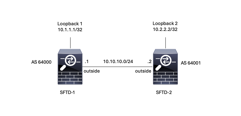 Image 1. Diagram of Escenario
Loopback Configuration
Step 1. Click Devices > Device Management, then select the device where you want to configure the Loopback.
Step 2. Click Interfaces > All Interfaces.
Step 3. Click Add Interface > Loopback Interface.
 Image 2. Add Interface Loopback
Step 4. In the General section, configure the name of the Loopback, check the Enabled box, and configure the Loopback ID.
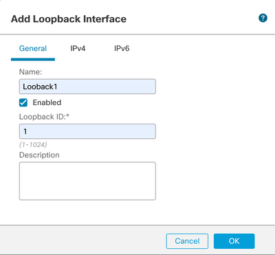 Image 3. Basic Loopback Interface Configuration
Step 5. In the IPv4 section, select the Use Static IP option in the IP Type section, configure the Loopback IP, then click OK to save the changes.
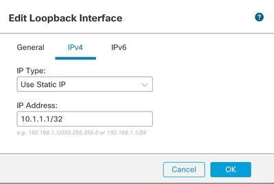 Image 4. Loopback IP Address Configuration
Step 6. Click Save.
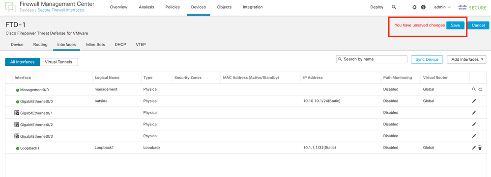 Image 5. Save the Loopback Interface Configuration
Step 7. Repeat the process with the second Firewall.
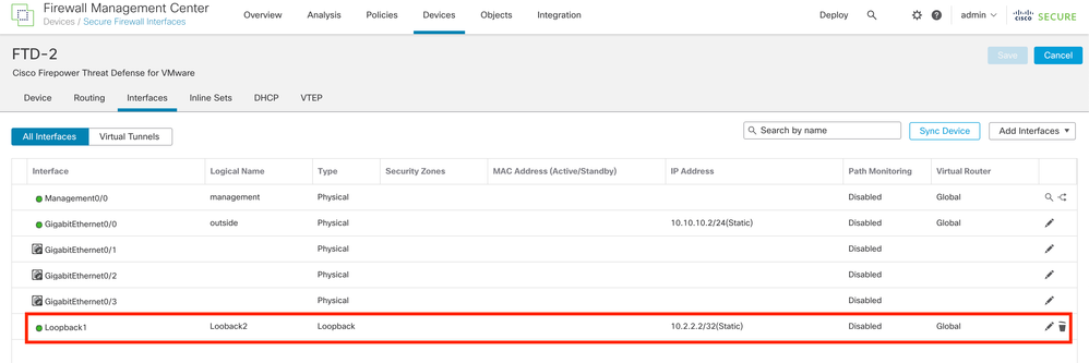 Image 6. Loopback Interface Configuration on peer
Static Route Configuration
A static route must be configured to ensure the remote peer address (Loopback) used for peering is reachable through the desired interface.
Step 1. Click Devices > Device Management, then select the device you want to configure the static route.
Step 2. Click Routing > Manage Virtual Routers > Static Route, then click Add Route.
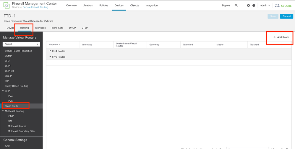 Image 7. Add New Static Route
Step 3. Check the IPv4 option for Type. Select the physical interface used to reach the Loopback of the remote peer in the Interface option, and then specify the next hop to reach the Loopback on the Gateway section.
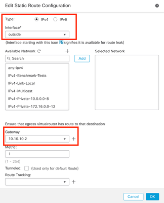 Image 8. Static Route Configuration
Step 4. Click the icon (+) next to the Available Network section.
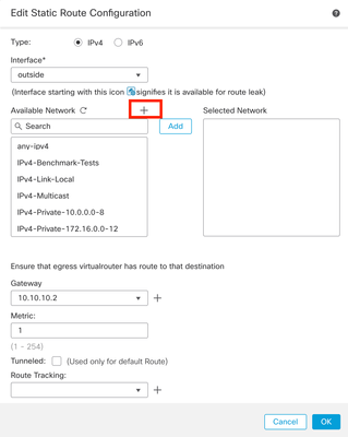 Image 9. Add New Network Object
Step 5. Configure a name for reference and the IP of the Looback of the remote peer and Save.
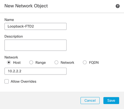 Image 10. Configure Network Destination In the Static Route
Step 6. Search the new object created in the search bar, select it, then click Add, and then click OK.
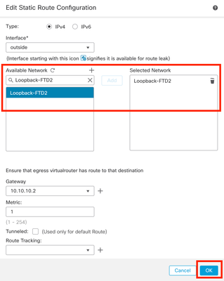 Image 11. Configure Next Hop in Static Route
Step 7. Click Save.
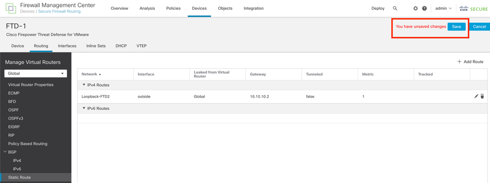 Image 12. Save the Static Route Interface Configuration
Step 8. Repeat the process with the second Firewall.
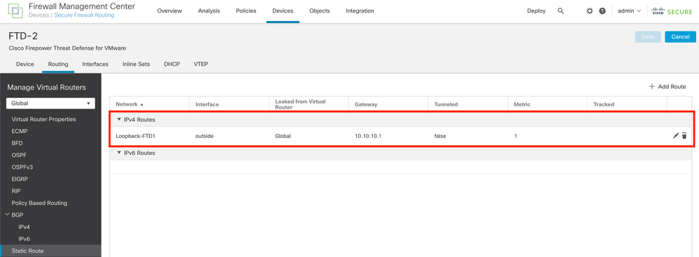 Image 13. Configure Static Route on Peer
BGP Configuration
Step 1. Click Devices > Device Management, and select the device you want to enable BGP.
Step 2. Click Routing > Manage Virtual Routers > General Settings, and then click BGP.
Step 3. Check the Enable BGP box, then configure the local AS of the Firewall into the AS Number section.
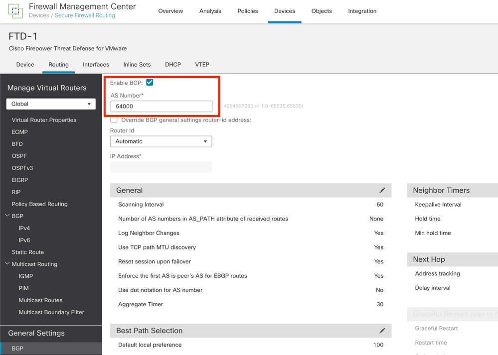 Image 14. Enable BGP Globally
Step 4. Save the changes by clicking the Save button.
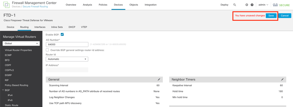 Image 15. Save the BGP Enable Change
Step 5. In the Manage Virtual Routers section, go to the BGP option, and then click IPv4.
Step 6. Check the Enable IPv4 box, then click Neighbor, and then click + Add.
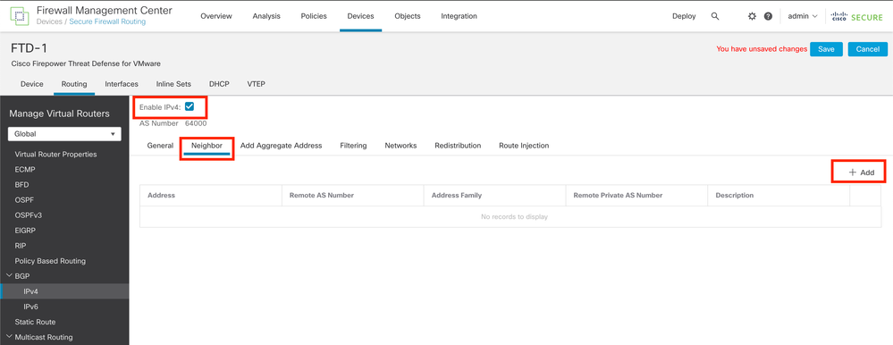 Image 16. Add a New BGP Peer
Step 7. Configure the IP address of the remote peer in the IP Address section, then configure the AS of the remote peer in the Remote AS section, and check the Enable address box.
Step 8. Select the local interface Loopback in the Update Source section.
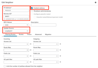 Image 17. Basic BGP Peer Parameters
Note: The Update Source option enables the neighbor update-source command, used to permit any operational interface (including Loopbacks). This command can be specified to establish TCP connections.
Step 9. Click Advanced, then configure the number 2 in the TTL Hops option, and click OK.
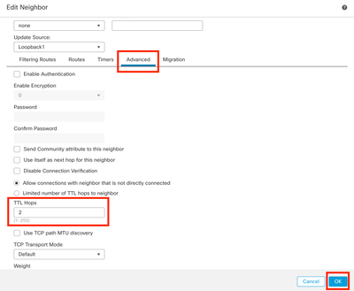 Image 18. Configure the TTLs Hop Number
Note: The TTL Hops option enables the ebgp-multihop command, used to change the TTL value to allow the packet to reach the external BGP peer that is not directly connected or has an interface other than the directly connected interface.
Step 10. Click Save and deploy the changes.
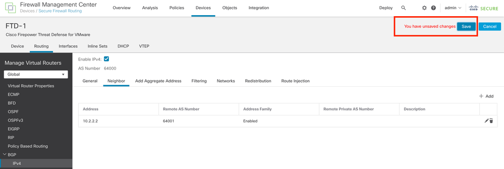 Image 19. Save the BGP Configuration
Step 11. Repeat the process with the second Firewall.
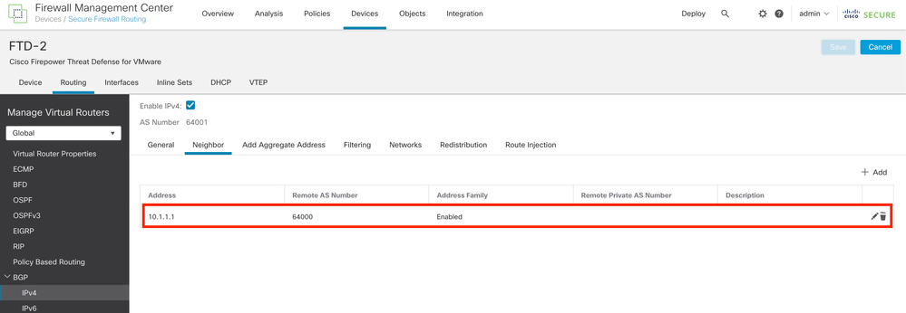 Image 20. Configure BGP on Peer
Verify
Step 1. Verify the Loopback and static route configuration, then check the connectivity between BGP peers with a ping test.
show running-config interface interface_name
show running-config route
show destination_ip
|
SFTD-1
|
SFTD-2
|
|
show running-config interface Loopback1
interface Loopback1
nameif Loopback1
ip address 10.1.1.1 255.255.255.255
show running-config route
route outside 10.2.2.2 255.255.255.255 10.10.10.2 1
ping 10.2.2.2
Sending 5, 100-byte ICMP Echos to 10.2.2.2, timeout is 2 seconds:
!!!!!
Success rate is 100 percent (5/5), round-trip min/avg/max = 1/1/1 ms
|
show running-config interface Loopback1
interface Loopback1
nameif Looback2
ip address 10.2.2.2 255.255.255.255
show running-config route
route outside 10.1.1.1 255.255.255.255 10.10.10.1 1
ping 10.1.1.1
Sending 5, 100-byte ICMP Echos to 10.1.1.1, timeout is 2 seconds:
!!!!!
Success rate is 100 percent (5/5), round-trip min/avg/max = 1/1/1 ms
|
Step 2. Verify the BGP configuration, then ensure that the BGP peering is established.
show running-config router bgp
show bgp neighbors
show bgp summary
|
SFTD-1
|
SFTD-2
|
|
show running-config router bgp
router bgp 64000
bgp log-neighbor-changes
bgp router-id vrf auto-assign
address-family ipv4 unicast
neighbor 10.2.2.2 remote-as 64001
neighbor 10.2.2.2 ebgp-multihop 2
neighbor 10.2.2.2 transport path-mtu-discovery disable
neighbor 10.2.2.2 update-source Loopback1
neighbor 10.2.2.2 activate
no auto-summary
no synchronization
exit-address-family
!
show bgp neighbors | i BGP
BGP neighbor is 10.2.2.2, vrf single_vf, remote AS 64001, external link
BGP version 4, remote router ID 10.2.2.2
BGP state = Established, up for 1d15h
BGP table version 7, neighbor version 7/0
External BGP neighbor may be up to 2 hops away.
show bgp summary
BGP router identifier 10.1.1.1, local AS number 64000
BGP table version is 7, main routing table version 7
Neighbor V AS MsgRcvd MsgSent TblVer InQ OutQ Up/Down State/PfxRcd
10.2.2.2 4 64001 2167 2162 7 0 0 1d15h 0
|
show running-config router bgp
router bgp 64001
bgp log-neighbor-changes
bgp router-id vrf auto-assign
address-family ipv4 unicast
neighbor 10.1.1.1 remote-as 64000
neighbor 10.1.1.1 ebgp-multihop 2
neighbor 10.1.1.1 transport path-mtu-discovery disable
neighbor 10.1.1.1 update-source Looback2
neighbor 10.1.1.1 activate
no auto-summary
no synchronization
exit-address-family
!
show bgp neighbors | i BGP
BGP neighbor is 10.1.1.1, vrf single_vf, remote AS 64000, external link
BGP version 4, remote router ID 10.1.1.1
BGP state = Established, up for 1d16h
BGP table version 1, neighbor version 1/0
External BGP neighbor may be up to 2 hops away.
show bgp summary
BGP router identifier 10.2.2.2, local AS number 64001
BGP table version is 1, main routing table version 1
Neighbor V AS MsgRcvd MsgSent TblVer InQ OutQ Up/Down State/PfxRcd
10.1.1.1 4 64000 2168 2173 1 0 0 1d16h 0
|
Troubleshooting
If you are experiencing any issues during the process, please review this article:
• Border Gateway Protocol (BGP)


 Feedback