IPsec Tunnel Between PIX 7.x and VPN 3000 Concentrator Configuration Example
Available Languages
Contents
Introduction
This document provides a sample configuration for how to establish a LAN-to-LAN IPsec VPN tunnel between a PIX Firewall 7.x and a Cisco VPN 3000 Concentrator.
Refer to PIX/ASA 7.x Enhanced Spoke-to-Client VPN with TACACS+ Authentication Configuration Example in order to learn more about the scenario where the LAN-to-LAN tunnel between the PIXes also allows for a VPN Client to access the spoke PIX through the hub PIX.
Refer to PIX/ASA 7.x Security Appliance to an IOS Router LAN-to-LAN IPsec Tunnel Configuration Example in order to learn more about the scenario where the LAN-to-LAN tunnel between the PIX/ASA and an IOS Router.
Prerequisites
Requirements
Ensure that you meet these requirements before you attempt this configuration:
-
This document requires a basic understanding of IPsec protocol. Refer to An Introduction to IPsec Encryption to learn more about IPsec.
Components Used
The information in this document is based on these software and hardware versions:
-
Cisco PIX 500 Series Security Appliance with software version 7.1(1)
-
Cisco VPN 3060 Concentrator with software version 4.7.2(B)
Note: PIX 506/506E does not support 7.x.
The information in this document was created from the devices in a specific lab environment. All of the devices used in this document started with a cleared (default) configuration. If your network is live, make sure that you understand the potential impact of any command.
In order to configure PIX 6.x, refer to LAN-to-LAN IPSec Tunnel Between the Cisco VPN 3000 Concentrator and PIX Firewall Configuration Example.
Conventions
Refer to the Cisco Technical Tips Conventions for more information on document conventions.
Configure
In this section, you are presented with the information to configure the features described in this document.
Note: Use the Command Lookup Tool (registered customers only) to obtain more information on the commands used in this section.
Network Diagram
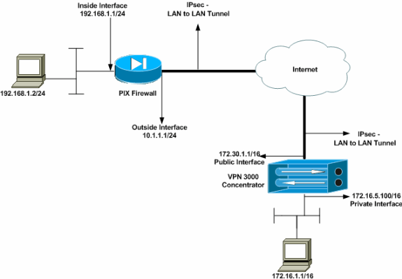
This document uses this network setup:
Configure the PIX
| PIX |
|---|
PIX7#show running-config : Saved : PIX Version 7.1(1) ! hostname PIX7 enable password 8Ry2YjIyt7RRXU24 encrypted names ! !--- Configures the outside interface of the PIX. !--- By default, the security level for the outside interface is 0. interface Ethernet0 nameif outside security-level 0 ip address 10.1.1.1 255.255.255.0 ! !--- Configures the inside interface of the PIX. !--- By default, the security level for the inside interface is 100. interface Ethernet1 nameif inside security-level 100 ip address 192.168.1.1 255.255.255.0 ! !--- Defines the IP addresses that should not be NATed. access-list nonat extended permit ip 192.168.1.0 255.255.255.0 172.16.0.0 255.255.0.0 access-list outside extended permit icmp any any !--- Defines the IP addresses that can communicate via the IPsec tunnel. access-list 101 extended permit ip 192.168.1.0 255.255.255.0 172.16.0.0 255.255.0.0 access-list OUT extended permit ip any any pager lines 24 mtu outside 1500 mtu inside 1500 no failover asdm image flash:/asdm-504.bin no asdm history enable arp timeout 14400 nat (inside) 0 access-list nonat access-group OUT in interface outside route outside 0.0.0.0 0.0.0.0 10.1.1.2 1 !--- Output is suppressed. !--- These are the IPsec parameters that are negotiated with the client. crypto ipsec transform-set my-set esp-aes-256 esp-sha-hmac crypto map mymap 20 match address 101 crypto map mymap 20 set peer 172.30.1.1 crypto map mymap 20 set transform-set my-set crypto map mymap interface outside !--- These are the Phase I parameters negotiated by the two peers. isakmp enable outside isakmp policy 10 authentication pre-share isakmp policy 10 encryption aes-256 isakmp policy 10 hash sha isakmp policy 10 group 2 isakmp policy 10 lifetime 86400 !--- A tunnel group consists of a set of records !--- that contain tunnel connection policies. The two attributes !--- are General and IPsec. Use the remote peer IP address as the !--- name of the Tunnel group. In this example 172.30.1.1 is the peer IP address. !--- Refer to Tunnel Group for more information. tunnel-group 172.30.1.1 type ipsec-l2l tunnel-group 172.30.1.1 ipsec-attributes pre-shared-key * !--- Output is suppressed. ! : end PIX7# |
Configure the VPN 3000 Concentrator
VPN Concentrators are not pre-programmed with IP addresses in their factory settings. You have to use the console port in order to configure the initial configurations which are a menu-based command-line interface (CLI). Refer to Configuring VPN Concentrators through the Console for information on how to configure through the console.
After you configure the IP address on the Ethernet 1 (private) interface, you can configure the rest with either the CLI or via the browser interface. The browser interface supports both HTTP and HTTP over Secure Socket Layer (SSL).
These parameters are configured through the console:
-
Time/Date—The correct time and date are very important. They help ensure that logging and accounting entries are accurate, and that the system can create a valid security certificate.
-
Ethernet 1 (private) interface—The IP address and mask (from the network topology 172.16.5.100/16).
The VPN Concentrator is now accessible through an HTML browser from the inside network. Refer to Using the Command-Line Interface for Quick Configuration for information on how to configure the VPN Concentrator in CLI mode.
Type the IP address of the private interface from the web browser in order to enable the GUI interface.
Click the save needed icon to save changes to memory. The factory default username and password are admin, which is case sensitive.
-
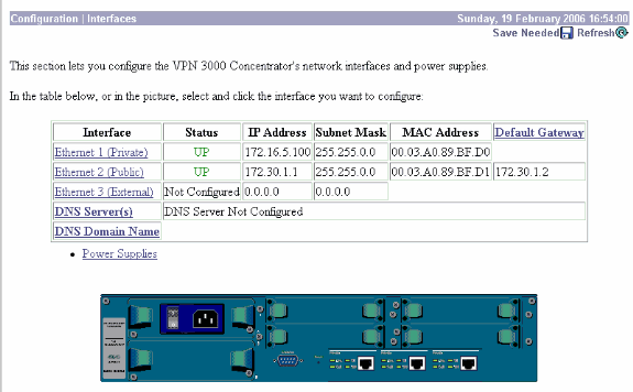
Launch the GUI and select Configuration > Interfaces to configure the IP address for the public interface and the default gateway.
-
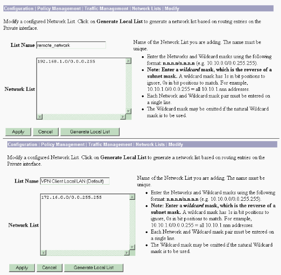
Select Configuration > Policy Management > Traffic Management > Network Lists > Add or Modify to create the network lists that define the traffic to be encrypted.
Add both the local and remote networks here. The IP addresses should mirror those in the access list configured on the remote PIX.
In this example, the two network lists are remote_network and VPN Client Local LAN.
-
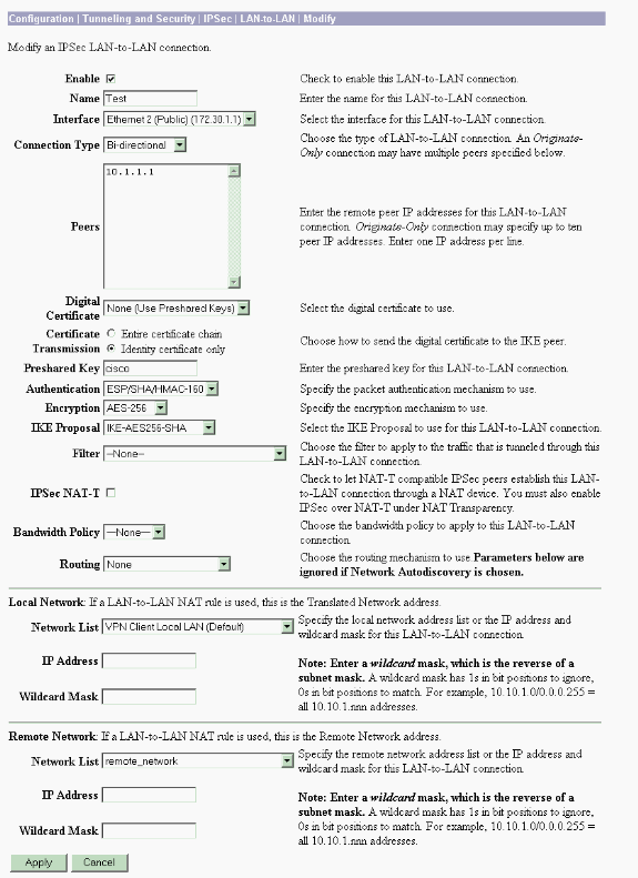
Select Configuration > System > Tunneling Protocols > IPSec LAN-to-LAN > Add to configure the IPsec LAN-to-LAN tunnel. Click Apply when you are finished.
Enter the peer IP address, the network lists created in step 2, the IPsec and ISAKMP parameters, and the pre-shared key.
In this example the peer IP address is 10.1.1.1, the network lists are remote_network and VPN Client Local LAN, and cisco is the pre-shared key.
-
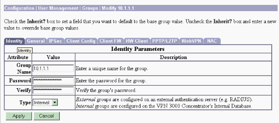
Select Configuration > User Management > Groups > Modify 10.1.1.1 to view the automatically generated Group information.
Note: Do not modify these group settings.
Verify
Use this section to confirm that your configuration works properly.
Verify the PIX
The Output Interpreter Tool (registered customers only) (OIT) supports certain show commands. Use the OIT to view an analysis of show command output.
-
show isakmp sa —Displays all current IKE security associations (SAs) at a peer. The state MM_ACTIVE denotes that Main Mode is used to set up the IPsec VPN tunnel.
In this example the PIX Firewall initiates the IPsec connection. The peer IP address is 172.30.1.1 and uses Main Mode to establish the connection.
PIX7#show isakmp sa Active SA: 1 Rekey SA: 0 (A tunnel will report 1 Active and 1 Rekey SA during rekey) Total IKE SA: 1 1 IKE Peer: 172.30.1.1 Type : L2L Role : initiator Rekey : no State : MM_ACTIVE -
show ipsec sa —Displays the settings used by current SAs. Check for the peer IP addresses, the networks accessible at both the local and remote ends, and the transform set that is used. There are two ESP SAs, one in each direction.
PIX7#show ipsec sa
interface: outside
    Crypto map tag: mymap, seq num: 20, local addr: 10.1.1.1

      access-list 101 permit ip 192.168.1.0 255.255.255.0 172.16.0.0 255.255.0.0

      local ident (addr/mask/prot/port): (192.168.1.0/255.255.255.0/0/0)
      remote ident (addr/mask/prot/port): (172.16.0.0/255.255.0.0/0/0)
      current_peer: 172.30.1.1

      #pkts encaps: 4, #pkts encrypt: 4, #pkts digest: 4
      #pkts decaps: 4, #pkts decrypt: 4, #pkts verify: 4
      #pkts compressed: 0, #pkts decompressed: 0
      #pkts not compressed: 4, #pkts comp failed: 0, #pkts decomp failed: 0
      #send errors: 0, #recv errors: 0

      local crypto endpt.: 10.1.1.1, remote crypto endpt.: 172.30.1.1

      path mtu 1500, ipsec overhead 76, media mtu 1500
      current outbound spi: 136580F6

    inbound esp sas:
      spi: 0xF24F4675 (4065281653)
         transform: esp-aes-256 esp-sha-hmac
         in use settings ={L2L, Tunnel,}
         slot: 0, conn_id: 1, crypto-map: mymap
         sa timing: remaining key lifetime (kB/sec): (3824999/28747)
         IV size: 16 bytes
         replay detection support: Y
    outbound esp sas:
      spi: 0x136580F6 (325419254)
         transform: esp-aes-256 esp-sha-hmac
         in use settings ={L2L, Tunnel,}
         slot: 0, conn_id: 1, crypto-map: mymap
         sa timing: remaining key lifetime (kB/sec): (3824999/28745)
         IV size: 16 bytes
         replay detection support: Y
Use the clear ipsec sa and clear isakmp sa commands to reset the tunnel.
Verify the VPN 3000 Concentrator
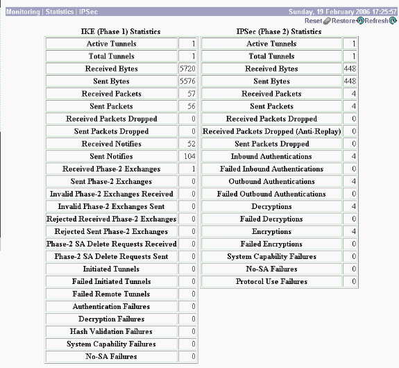
Select Monitoring > Statistics > IPsec to verify if the tunnel has come up in the VPN 3000 Concentrator. This contains the statistics for both IKE and IPsec parameters.
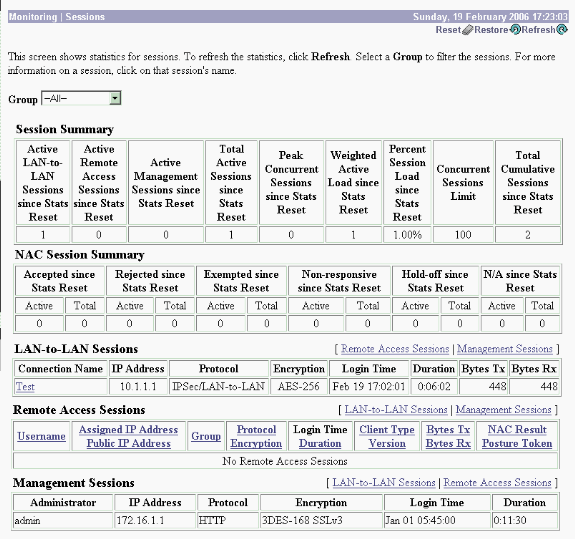
You can actively monitor the session at Monitoring > Sessions. You can reset the IPsec tunnel here.
Troubleshoot
This section provides information you can use to troubleshoot your configuration.
Troubleshoot the PIX
The Output Interpreter Tool (registered customers only) (OIT) supports certain show commands. Use the OIT to view an analysis of show command output.
Note: Refer to Important Information on Debug Commands before you use debug commands.
The debug commands on PIX for VPN tunnels are:
-
debug crypto isakmp —Debugs ISAKMP SA negotiations.
-
debug crypto ipsec —Debugs IPsec SA negotiations.
Troubleshoot the VPN 3000 Concentrator
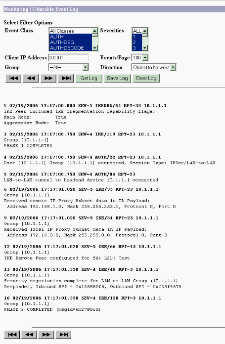
Similar to debug commands on the Cisco routers, you can configure Event Classes to view all alarms. Select Configuration > System > Events > Classes > Add to turn on the logging of Event Classes.
Select Monitoring > Filterable Event Log to monitor the enabled Events.
PFS
In IPsec negotiations, Perfect Forward Secrecy (PFS) ensures that each new cryptographic key is unrelated to any previous key. Either enable or disable PFS on both the tunnel peers, otherwise the LAN-to-LAN (L2L) IPsec tunnel is not established in the PIX/ASA.
PFS is disabled by default. In order to enable PFS use the pfs command with the enable keyword in group-policy configuration mode. In order to disable PFS, enter the disable keyword.
hostname(config-group-policy)#pfs {enable | disable}
In order to remove the PFS attribute from the running configuration, enter the no form of this command. A group policy can inherit a value for PFS from another group policy. Enter the no form of this command in order to prevent inheriting a value.
hostname(config-group-policy)#no pfs
Related Information
Revision History
| Revision | Publish Date | Comments |
|---|---|---|
1.0 |
16-Oct-2008 |
Initial Release |
Contact Cisco
- Open a Support Case

- (Requires a Cisco Service Contract)
 Feedback