IKEv2 with TrustSec SGT Inline Tagging and SGT-Aware Zone-Based Firewall Configuration Example
Available Languages
Contents
Introduction
This document describes how to use Internet Key Exchange Version 2 (IKEv2) and a security group tag (SGT) in order to tag packets sent to a VPN tunnel. The description includes a typical deployment and use case. This document also explains an SGT-aware Zone-Based Firewall (ZBF) and presents two scenarios:
- A ZBF that is based on SGT tags received from IKEv2 tunnel
- A ZBF that is based on SGT eXchange Protocol (SXP) mapping
All examples include packet level debugs in order to verify how the SGT tag is transmitted.
Prerequisites
Requirements
Cisco recommends that you have knowledge of these topics:
- Basic knowledge of TrustSec components
- Basic knowledge of command-line interface (CLI) configuration of Cisco Catalyst switches
- Experience in configuration of a Cisco Identity Services Engine (ISE)
- Basic knowledge of Zone-Based Firewall
- Basic knowledge of IKEv2
Components Used
The information in this document is based on these software and hardware versions:
- Microsoft Windows 7 and Microsoft Windows XP
- Cisco Catalyst 3750-X Software Release 15.0 and later
- Cisco Identity Services Engine Software Release 1.1.4 and later
- Cisco 2901 Integrated Services Router (ISR) with Software Release 15.3(2)T or later
The information in this document was created from the devices in a specific lab environment. All of the devices used in this document started with a cleared (default) configuration. If your network is live, make sure that you understand the potential impact of any command.
Security Group Tag (SGT)
The SGT is part of the Cisco TrustSec solution architecture, which is designed to use flexible security policies that are not based on IP address.
Traffic in the TrustSec cloud is classified and marked with an SGT tag. You can build security policies that filter the traffic based on that tag. All policies are centrally manged from the ISE and are deployed to all devices in the TrustSec cloud.
In order to pass the information about the SGT tag, Cisco has modified the Ethernet frame similar to the way modifications were made for 802.1q tags. The modified Ethernet frame can be understood only by selected Cisco devices. This is the modified format:
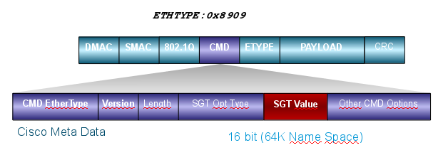
The Cisco Meta Data (CMD) field is inserted directly after the source mac address field (SMAC) or the 802.1q field if it is used (as in this example).
To connect TrustSec clouds via the VPN, an extension for the IKE and IPsec protocols has been created. The extension, called IPsec inline tagging, allows SGT tags to be sent in the Encapsulating Security Payload (ESP) packets. The ESP payload is modified to carry an 8-byte CMD field just before the payload of the packet itself. For example, the encrypted Internet Control Message Protocol (ICMP) packet sent over the Internet contains [IP][ESP][CMD][IP][ICMP][DATA].
Detailed information is presented in the second part of the article.
Configure
Network Diagram
Traffic Flow
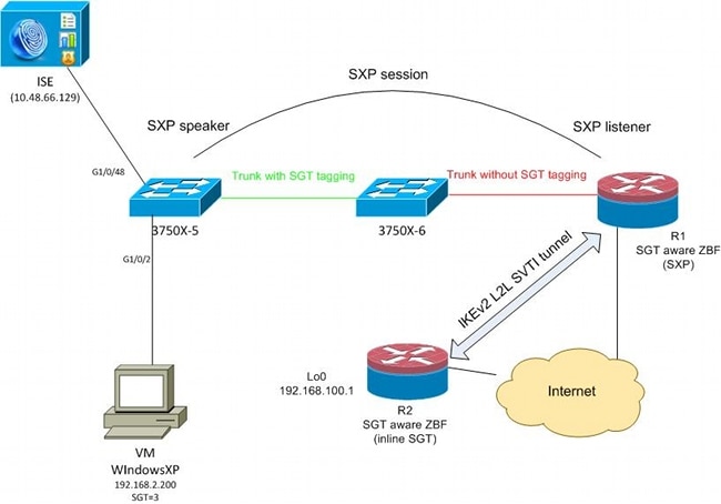
In this network, 3750X-5 and 3750X-6 are Catalyst switches inside the TrustSec cloud. Both switches use automatic Protected Access Credentials (PACs) provisioning in order to join the cloud. 3750X-5 has been used as a seed, and 3750X-6 as a non-seed device. Traffic between both switches is encrypted with MACsec and is correctly tagged.
WindowsXP uses 802.1x in order to access the network. After successful authentication, the ISE returns the SGT tag attribute that will be applied for that session. All traffic sourced from that PC is tagged with SGT=3.
Router 1 (R1) and Router 2 (R2) are 2901 ISRs. Because ISR G2 does not currently support SGT tagging, R1 and R2 are outside of the TrustSec cloud and do not understand the Ethernet frames that were modified with CMD fields in order to pass the SGT tags. Thus, SXP is used in order to forward information about IP/SGT mapping from 3750X-5 to R1.
R1 has an IKEv2 tunnel that is configured to protect traffic destined to a remote location (192.168.100.1) and that has inline tagging enabled. After IKEv2 negotiation, R1 starts to tag ESP packets sent to R2. Tagging is based on the SXP data received from 3750X-5.
R2 can receive that traffic and, based on the received SGT tag, can perform specific actions defined by the ZBF.
The same can be done on R1. SXP mapping allows R1 to drop a packet received from the LAN based on an SGT tag, even if SGT frames are not supported.
TrustSec Cloud Configuration
The first step in configuration is to build a TrustSec cloud. Both 3750 switches need to:
- Obtain a PAC, which is used for authentication to the TrustSec cloud (ISE).
- Authenticate and pass the Network Device Admission Control (NDAC) process.
- Use the Security Association Protocol (SAP) for MACsec negotiation on a link.
This step is necessary for this use case, but is not necessary for the SXP protocol to work correctly. R1 does not need to get a PAC or environment data from ISE in order to perform SXP mapping and IKEv2 inline tagging.
Verification
The link between 3750X-5 and 3750X-6 uses MACsec encryption negotiated by 802.1x. Both switches trust and accept the SGT tags received by the peer:
bsns-3750-5#show cts interface
Global Dot1x feature is Enabled
Interface GigabitEthernet1/0/20:
    CTS is enabled, mode:    DOT1X
    IFC state:               OPEN
    Authentication Status:   SUCCEEDED
        Peer identity:       "3750X6"
        Peer's advertised capabilities: "sap"
        802.1X role:         Supplicant
        Reauth period applied to link:  Not applicable to Supplicant role
    Authorization Status:    SUCCEEDED
        Peer SGT:            0:Unknown
        Peer SGT assignment: Trusted
    SAP Status:              SUCCEEDED
        Version:             2
        Configured pairwise ciphers:
            gcm-encrypt

        Replay protection:      enabled
        Replay protection mode: STRICT

        Selected cipher:        gcm-encrypt

    Propagate SGT:           Enabled
    Cache Info:
        Cache applied to link : NONE

    Statistics:
        authc success:              32
        authc reject:               1543
        authc failure:              0
        authc no response:          0
        authc logoff:               2
        sap success:                32
        sap fail:                   0
        authz success:              50
        authz fail:                 0
        port auth fail:             0
It is not possible to apply a role-based access control list (RBACL) directly on switches. Those policies are configured on ISE and are automatically downloaded on the switches.
Client Configuration
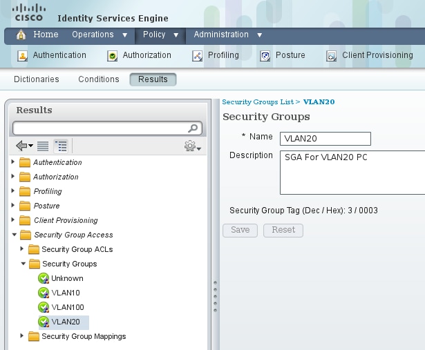
The client can use 802.1x, MAC authentication bypass (MAB), or web authentication. Remember to configure ISE so that the correct security group for the authorization rule is returned:
Verification
Verify the client configuration:
bsns-3750-5#show authentication sessions interface g1/0/2
            Interface:  GigabitEthernet1/0/2
          MAC Address:  0050.5699.4ea1
           IP Address:  192.168.2.200
            User-Name:  cisco
               Status:  Authz Success
               Domain:  DATA
      Security Policy:  Should Secure
      Security Status:  Unsecure
       Oper host mode:  multi-auth
     Oper control dir:  both
        Authorized By:  Authentication Server
          Vlan Policy:  20
                  SGT:  0003-0
      Session timeout:  N/A
         Idle timeout:  N/A
    Common Session ID:  C0A80001000006367BE96D54
      Acct Session ID:  0x00000998
               Handle:  0x8B000637

Runnable methods list:
       Method   State
       dot1x    Authc Success
       mab      Not run
From this point on, client traffic sent from 3750X-5 to other switches within the TrustSec cloud is tagged with SGT=3.
See ASA and Catalyst 3750X Series Switch TrustSec Configuration Example and Troubleshoot Guide for an example of authorization rules.
SGT Exchange Protocol Between 3750X-5 and R1
R1 cannot join the TrustSec cloud because it is a 2901 ISR G2 router that does not understand Ethernet frames with CMD fields. So, SXP is configured on the 3750X-5:
bsns-3750-5#show run | i sxp
cts sxp enable
cts sxp default source-ip 192.168.1.10
cts sxp default password cisco
cts sxp connection peer 192.168.1.20 password default mode local
SXP is also configured on R1:
BSNS-2901-1#show run | i sxp
cts sxp enable
cts sxp default source-ip 192.168.1.20
cts sxp default password cisco
cts sxp connection peer 192.168.1.10 password default mode local listener
   hold-time 0 0
Verification
Ensure that R1 is receiving the IP/SGT mapping information:
BSNS-2901-1#show cts sxp sgt-map
SXP Node ID(generated):0xC0A80214(192.168.2.20)
IP-SGT Mappings as follows:
IPv4,SGT: <192.168.2.200 , 3>
source  : SXP;
Peer IP : 192.168.1.10;
Ins Num : 1;
Status  : Active;
Seq Num : 1
Peer Seq: 0
R1 now knows that all traffic received from 192.168.2.200 should be treated as if it is tagged as SGT=3.
IKEv2 Configuration Between R1 and R2
This is a simple Static Virtual Tunnel Interfaces (SVTI)-based scenario with IKEv2 smart defaults. Pre-shared keys are used for authentication, and null encryption is used for ease of ESP packet analysis. All traffic to 192.168.100.0/24 is sent through the Tunnel1 interface.
This is the configuration on R1:
crypto ikev2 keyring ikev2-keyring
 peer 192.168.1.21
  address 192.168.1.21
  pre-shared-key cisco
 !
crypto ikev2 profile ikev2-profile
 match identity remote address 192.168.1.21 255.255.255.255
 authentication remote pre-share
 authentication local pre-share
 keyring local ikev2-keyring

crypto ipsec transform-set tset esp-null esp-sha-hmac
 mode tunnel
!
crypto ipsec profile ipsec-profile
 set transform-set tset
 set ikev2-profile ikev2-profile

interface Tunnel1
 ip address 172.16.1.1 255.255.255.0
 tunnel source GigabitEthernet0/1.10
 tunnel mode ipsec ipv4
 tunnel destination 192.168.1.21
 tunnel protection ipsec profile ipsec-profile

interface GigabitEthernet0/1.10
 encapsulation dot1Q 10
 ip address 192.168.1.20 255.255.255.0

ip route 192.168.100.0 255.255.255.0 172.16.1.2
On R2, all return traffic to network 192.168.2.0/24 is sent through the Tunnel1 interface:
crypto ikev2 keyring ikev2-keyring
 peer 192.168.1.20
  address 192.168.1.20
  pre-shared-key cisco

crypto ikev2 profile ikev2-profile
 match identity remote address 192.168.1.20 255.255.255.255
 authentication remote pre-share
 authentication local pre-share
 keyring local ikev2-keyring

crypto ipsec transform-set tset esp-null esp-sha-hmac
 mode tunnel

crypto ipsec profile ipsec-profile
 set transform-set tset
 set ikev2-profile ikev2-profile

interface Loopback0
 description Protected Network
 ip address 192.168.100.1 255.255.255.0

interface Tunnel1
 ip address 172.16.1.2 255.255.255.0
 tunnel source GigabitEthernet0/1.10
 tunnel mode ipsec ipv4
 tunnel destination 192.168.1.20
 tunnel protection ipsec profile ipsec-profile

interface GigabitEthernet0/1.10
 encapsulation dot1Q 10
 ip address 192.168.1.21 255.255.255.0

ip route 192.168.2.0 255.255.255.0 172.16.1.1
Only one command is required on both routers in order to enable inline tagging: the crypto ikev2 cts sgt command.
Verification
Inline tagging needs to be negotiated. In first and second IKEv2 packet, a specific Vendor ID is being sent:
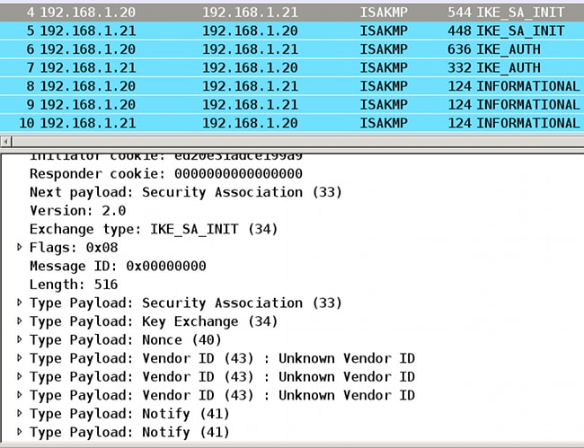
There are three Vendor IDs (VIDs) that are unknown by Wireshark. They are related to:
- DELETE-REASON, supported by Cisco
- FlexVPN, supported by Cisco
- SGT inline taggging
The debugs verify this. R1, which is an IKEv2 initiator, sends:
debug crypto ikev2 internal

*Jul 25 07:58:10.633: IKEv2:Construct Vendor Specific Payload: DELETE-REASON
*Jul 25 07:58:10.633: IKEv2:(1): Sending custom vendor id : CISCO-CTS-SGT

*Jul 25 07:58:10.633: IKEv2:Construct Vendor Specific Payload: (CUSTOM)
*Jul 25 07:58:10.633: IKEv2:Construct Vendor Specific Payload: (CUSTOM)
R1 receives a second IKEv2 packet and the same VID:
*Jul 25 07:58:10.721: IKEv2:Parse Vendor Specific Payload: CISCO-DELETE-REASON VID
*Jul 25 07:58:10.721: IKEv2:Parse Vendor Specific Payload: (CUSTOM) VID
*Jul 25 07:58:10.721: IKEv2:Parse Vendor Specific Payload: (CUSTOM) VID
*Jul 25 07:58:10.721: IKEv2:Parse Notify Payload: NAT_DETECTION_SOURCE_IP
   NOTIFY(NAT_DETECTION_SOURCE_IP)
*Jul 25 07:58:10.725: IKEv2:Parse Notify Payload: NAT_DETECTION_DESTINATION_IP
   NOTIFY(NAT_DETECTION_DESTINATION_IP)

*Jul 25 07:58:10.725: IKEv2:(1): Received custom vendor id : CISCO-CTS-SGT
Thus, both sides agree to put CMD data at the start of the ESP payload.
Check the IKEv2 security association (SA) in order to verify this agreement:
BSNS-2901-1#show crypto ikev2 sa detailed
 IPv4 Crypto IKEv2  SA

Tunnel-id Local                 Remote                fvrf/ivrf            Status
1         192.168.1.20/500      192.168.1.21/500      none/none            READY
      Encr: AES-CBC, keysize: 256, Hash: SHA512, DH Grp:5, Auth sign: PSK, Auth
         verify: PSK
      Life/Active Time: 86400/225 sec
      CE id: 1019, Session-id: 13
      Status Description: Negotiation done
      Local spi: 1A4E0F7D5093D2B8       Remote spi: 08756042603C42F9
      Local id: 192.168.1.20
      Remote id: 192.168.1.21
      Local req msg id:  2              Remote req msg id:  0
      Local next msg id: 2              Remote next msg id: 0
      Local req queued:  2              Remote req queued:  0
      Local window:      5              Remote window:      5
      DPD configured for 0 seconds, retry 0
      Fragmentation not configured.
      Extended Authentication not configured.
      NAT-T is not detected
      Cisco Trust Security SGT is enabled
      Initiator of SA : Yes

 IPv6 Crypto IKEv2  SA
After it sends traffic from Windows client towards 192.168.100.1, R1 shows:
BSNS-2901-1#sh crypto session detail
Crypto session current status

Code: C - IKE Configuration mode, D - Dead Peer Detection
K - Keepalives, N - NAT-traversal, T - cTCP encapsulation
X - IKE Extended Authentication, F - IKE Fragmentation

Interface: Tunnel1
Uptime: 00:01:17
Session status: UP-ACTIVE
Peer: 192.168.1.21 port 500 fvrf: (none) ivrf: (none)
      Phase1_id: 192.168.1.21
      Desc: (none)
  IKEv2 SA: local 192.168.1.20/500 remote 192.168.1.21/500 Active
          Capabilities:(none) connid:1 lifetime:23:58:43
  IPSEC FLOW: permit ip 0.0.0.0/0.0.0.0 0.0.0.0/0.0.0.0
        Active SAs: 2, origin: crypto map
        Inbound:  #pkts dec'ed 4 drop 0 life (KB/Sec) 4227036/3522
        Outbound: #pkts enc'ed 9 drop 0 life (KB/Sec) 4227035/3522


BSNS-2901-1#show crypto ipsec sa detail

interface: Tunnel1
    Crypto map tag: Tunnel1-head-0, local addr 192.168.1.20

   protected vrf: (none)
   local  ident (addr/mask/prot/port): (0.0.0.0/0.0.0.0/0/0)
   remote ident (addr/mask/prot/port): (0.0.0.0/0.0.0.0/0/0)
   current_peer 192.168.1.21 port 500
     PERMIT, flags={origin_is_acl,}
    #pkts encaps: 9, #pkts encrypt: 9, #pkts digest: 9
    #pkts decaps: 4, #pkts decrypt: 4, #pkts verify: 4
    #pkts compressed: 0, #pkts decompressed: 0
    #pkts not compressed: 0, #pkts compr. failed: 0
    #pkts not decompressed: 0, #pkts decompress failed: 0
    #pkts no sa (send) 0, #pkts invalid sa (rcv) 0
    #pkts encaps failed (send) 0, #pkts decaps failed (rcv) 0
    #pkts invalid prot (recv) 0, #pkts verify failed: 0
    #pkts invalid identity (recv) 0, #pkts invalid len (rcv) 0
    #pkts replay rollover (send): 0, #pkts replay rollover (rcv) 0
    ##pkts replay failed (rcv): 0
    #pkts tagged (send): 9, #pkts untagged (rcv): 4
    #pkts not tagged (send): 0, #pkts not untagged (rcv): 0
    #pkts internal err (send): 0, #pkts internal err (recv) 0
    #send dummy packets 9, #recv dummy packets 0

     local crypto endpt.: 192.168.1.20, remote crypto endpt.: 192.168.1.21
     plaintext mtu 1454, path mtu 1500, ip mtu 1500, ip mtu idb
        GigabitEthernet0/1.10
     current outbound spi: 0x9D788FE1(2641924065)
     PFS (Y/N): N, DH group: none

     inbound esp sas:
      spi: 0xDE3D2D21(3728551201)
        transform: esp-null esp-sha-hmac ,
        in use settings ={Tunnel, }
        conn id: 2020, flow_id: Onboard VPN:20, sibling_flags 80000040,
           crypto map: Tunnel1-head-0
        sa timing: remaining key lifetime (k/sec): (4227036/3515)
        IV size: 0 bytes
        replay detection support: Y
        Status: ACTIVE(ACTIVE)

     inbound ah sas:

     inbound pcp sas:

     outbound esp sas:
      spi: 0x9D788FE1(2641924065)
        transform: esp-null esp-sha-hmac ,
        in use settings ={Tunnel, }
        conn id: 2019, flow_id: Onboard VPN:19, sibling_flags 80000040,
           crypto map: Tunnel1-head-0
        sa timing: remaining key lifetime (k/sec): (4227035/3515)
        IV size: 0 bytes
        replay detection support: Y
        Status: ACTIVE(ACTIVE)

     outbound ah sas:

     outbound pcp sas:
BSNS-2901-1#
Note that tagged packets have been sent.
For transit traffic, when R1 needs to tag traffic sent from the Windows client to R2, confirm that the ESP packet has been tagged correctly with SGT=3:
debug crypto ipsc metadata sgt
*Jul 23 19:01:08.590: IPsec SGT:: inserted SGT = 3 for src ip 192.168.2.200
Other traffic from the same VLAN, which is sourced from the switch, defaults to SGT=0:
*Jul 23 19:43:08.590: IPsec SGT:: inserted SGT = 0 for src ip 192.168.2.10
ESP Packet Level Verification
Use Embedded Packet Capture (EPC) in order to review the ESP traffic from R1 to R2, as show in this figure:
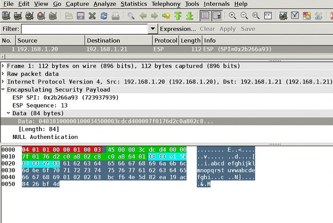
Wireshark has been used to decode null encryption for the security parameter index (SPI). In the IPv4 header, the source and destination IP are the Internet IP addresses of the routers (used as tunnel source and destination).
The ESP payload includes the 8-byte CMD field, which is highlighted in red:
- 0x04 - Next header, which is IP
- 0x01 - Length (4 bytes after the header, 8 bytes with the header)
- 0x01 - Version 01
- 0x00 - Reserved
- 0x00 - SGT length (4 bytes total)
- 0x01 - SGT type
- 0x0003 - SGT tag (the last two octets, which are 00 03; SGT is used for the Windows client)
Since IPsec IPv4 mode has been used for the tunnel interface, the next header is IP, which is highlighted in green. The source IP is c0 a8 02 c8 (192.168.2.200), and the destination IP is c0 a8 64 01 (192.168.100.1). The protocol number is 1, which is ICMP.
The last header is ICMP, highlighted in blue, with Type 08 and Code 8 (Echo Request).
The ICMP payload is next and is 32 bytes long (that is, letters from a to i). The payload in the figure is typical for a Windows client.
The rest of ESP headers follow the ICMP payload:
- 0x01 0x02 - Padding.
- 0x02 - Padding length.
- 0x63 - Next header that points to protocol 0x63, which is 'Any private encryption scheme.' This indicates that the next field (the first field in the ESP data) is the SGT tag.
- 12 bytes of Integrity Check Value.
The CMD field is inside the ESP payload, which is commonly encrypted.
IKEv2 Pitfalls: GRE or IPsec Mode
Until now, these examples have used tunnel mode IPsec IPv4. What happens if the Generic Routing Encapsulation (GRE) mode is used?
When the router encapsulates a transit IP packet into GRE, TrustSec views the packet as locally originated - that is, the source of the GRE packet is the router, not the Windows client. When the CMD field is added, the default tag (SGT=0) is always used instead of a specific tag.
When traffic is sent from the Windows client (192.168.2.200) in mode IPsec IPv4, you see SGT=3:
debug crypto ipsc metadata sgt
*Jul 23 19:01:08.590: IPsec SGT:: inserted SGT = 3 for src ip 192.168.2.200
But, after the tunnel mode is changed to GRE for the same traffic, you see that SGT=0. In this example, 192.168.1.20 is the tunnel source IP:
*Jul 25 20:34:08.577: IPsec SGT:: inserted SGT = 0 for src ip 192.168.1.20
See Cisco bug ID CSCuj25890, IOS IPSec Inline tagging for GRE mode: inserting router SGT. This bug was created in order to allow proper SGT propagation when you use GRE. SGT over DMVPN is supported from Cisco IOS® XE 3.13S
ZBF Based on SGT Tags from IKEv2
This is an example configuration of ZBF on R2. The VPN traffic with SGT=3 can be identified because all packets received from the IKEv2 tunnel are tagged (that is, they contain the CMD field). Thus, the VPN traffic can be dropped and logged:
class-map type inspect match-all TAG_3
 match security-group source tag 3
class-map type inspect match-all TAG_ANY
 match security-group source tag 0
!
policy-map type inspect FROM_VPN
 class type inspect TAG_3
  drop log
 class type inspect TAG_ANY
  pass log
 class class-default
  drop
!
zone security vpn
zone security inside
zone-pair security ZP source vpn destination self
 service-policy type inspect FROM_VPN

interface Tunnel1
 ip address 172.16.1.2 255.255.255.0
 zone-member security vpn
Verification
When a ping to 192.168.100.1 is sourced from the Windows client (SGT=3), the debugs show this:
*Jul 23 20:05:18.822: %FW-6-DROP_PKT: Dropping icmp session
   192.168.2.200:0 192.168.100.1:0 on zone-pair ZP class TAG_3 due to
   DROP action found in policy-map with ip ident 0
For a ping that is sourced from a switch (SGT=0), the debugs show this:
*Jul 23 20:05:39.486: %FW-6-PASS_PKT: (target:class)-(ZP:TAG_ANY)
   Passing icmp pkt 192.168.2.10:0 => 192.168.100.1:0 with ip ident 0
The firewall statistics from R2 are:
BSNS-2901-2#show policy-firewall stats all
Global Stats:
        Session creations since subsystem startup or last reset 0
        Current session counts (estab/half-open/terminating) [0:0:0]
        Maxever session counts (estab/half-open/terminating) [0:0:0]
        Last session created never
        Last statistic reset never
        Last session creation rate 0
        Maxever session creation rate 0
        Last half-open session total 0

policy exists on zp ZP
  Zone-pair: ZP

  Service-policy inspect : FROM_VPN

    Class-map: TAG_3 (match-all)
      Match: security-group source tag 3
      Drop
        4 packets, 160 bytes

    Class-map: TAG_ANY (match-all)
      Match: security-group source tag 0
      Pass
        5 packets, 400 bytes

    Class-map: class-default (match-any)
      Match: any
      Drop
        0 packets, 0 bytes
There are four drops (default number of ICMP Echo sent by Windows) and five accepts (default number for switch).
ZBF Based on SGT Mapping via SXP
It is possible to run SGT-aware ZBF on R1 and to filter traffic received from the LAN. Although that traffic is not SGT tagged, R1 has SXP mapping information and can treat that traffic as tagged.
In this example, a policy is used between the LAN and the VPN zones:
class-map type inspect match-all TAG_3
 match security-group source tag 3
class-map type inspect match-all TAG_ANY
 match security-group source tag 0
!
policy-map type inspect FROM_LAN
 class type inspect TAG_3
  drop log
 class type inspect TAG_ANY
  pass log
 class class-default
  drop
!
zone security lan
zone security vpn
zone-pair security ZP source lan destination vpn
 service-policy type inspect FROM_LAN

interface Tunnel1
 zone-member security vpn

interface GigabitEthernet0/1.20
 zone-member security lan
Verification
When ICMP Echo is sent from the Windows client, you can see the drops:
*Jul 25 09:22:07.380: %FW-6-DROP_PKT: Dropping icmp session 192.168.2.200:0
   192.168.100.1:0 on zone-pair ZP class TAG_3 due to  DROP action found in
   policy-map with ip ident 0

BSNS-2901-1#show policy-firewall stats all
Global Stats:
        Session creations since subsystem startup or last reset 0
        Current session counts (estab/half-open/terminating) [0:0:0]
        Maxever session counts (estab/half-open/terminating) [0:0:0]
        Last session created never
        Last statistic reset never
        Last session creation rate 0
        Maxever session creation rate 0
        Last half-open session total 0

policy exists on zp ZP
  Zone-pair: ZP

  Service-policy inspect : FROM_LAN

    Class-map: TAG_3 (match-all)
      Match: security-group source tag 3
      Drop
        4 packets, 160 bytes

    Class-map: TAG_ANY (match-all)
      Match: security-group source tag 0
      Pass
        5 packets, 400 bytes

    Class-map: class-default (match-any)
      Match: any
      Drop
        0 packets, 0 bytes
Because the SXP session is based on TCP, you can also build an SXP session via an IKEv2 tunnel between 3750X-5 and R2 and apply ZBF policies based on the tags on R2 without inline tagging.
Roadmap
GET VPN inline tagging is also supported on the ISR G2 and the Cisco ASR 1000 Series Aggregation Services Routers. The ESP packet has an additional 8 bytes for CMD field.
Support for Dynamic Multipoint VPN (DMVPN) is also planned.
See the Cisco TrustSec-Enabled Infrastructure roadmap for more information.
Verify
Verification procedures are included within the configuration examples.
Troubleshoot
There is currently no specific troubleshooting information available for this configuration.
Related Information
- Cisco TrustSec Switch Configuration Guide: Understanding Cisco TrustSec
- Book 1: Cisco ASA Series General Operations CLI Configuration Guide, 9.1: Configuring the ASA to Integrate with Cisco TrustSec
- Release Notes for Cisco TrustSec General Availability Releases: Release Notes for Cisco TrustSec 3.0 General Deployability 2013 Release
- Configuring IPsec Inline Tagging for TrustSec
- Cisco Group Encrypted Transport VPN Configuration Guide, Cisco IOS XE Release 3S: GET VPN Support of IPsec Inline Tagging for Cisco TrustSec
- Technical Support & Documentation - Cisco Systems
Revision History
| Revision | Publish Date | Comments |
|---|---|---|
1.0 |
04-Sep-2013 |
Initial Release |
Contact Cisco
- Open a Support Case

- (Requires a Cisco Service Contract)
 Feedback