Introduction
This document describes the configuration, verification, and operation of an Inline Pair Interface on a Firepower Threat Defense (FTD) appliance.
Prerequisites
Requirements
There are not specific requirements for this document.
Components Used
The information in this document is based on these software and hardware versions:
- ASA5512-X - FTD code 6.1.0.x
- Firepower Management Center (FMC) - code 6.1.0.x
The information in this document was created from the devices in a specific lab environment. All of the devices used in this document started with a cleared (default) configuration. If your network is live, ensure that you understand the potential impact of any command.
Related Products
This document can also be used with these hardware and software versions:
- ASA5506-X, ASA5506W-X, ASA5506H-X, ASA5508-X, ASA5516-X
- ASA5512-X, ASA5515-X, ASA5525-X, ASA5545-X, ASA5555-X
- FPR2100, FPR4100, FPR9300
- VMware (ESXi), Amazon Web Services (AWS), Kernel-based Virtual Machine (KVM)
- FTD software code 6.2.x and later
Background Information
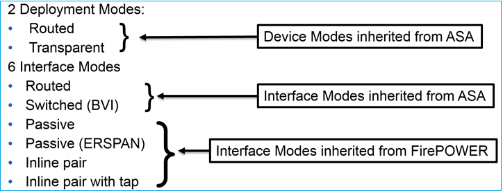
The Firepower Threat Defense (FTD) provides two Deployment modes and six Interface modes as shown in this image:
Note: You can mix interface modes on a single FTD appliance.
High level overview of the various FTD deployment and interface modes:
|
FTD interface mode
|
FTD Deployment mode
|
Description
|
Traffic can be dropped
|
|
Routed
|
Routed
|
Full LINA engine and Snort-engine checks
|
Yes
|
|
Switched
|
Transparent
|
Full LINA engine and Snort-engine checks
|
Yes
|
|
Inline Pair
|
Routed or Transparent
|
Partial LINA engine and full Snort-engine checks
|
Yes
|
|
Inline Pair with Tap
|
Routed or Transparent
|
Partial LINA engine and full Snort-engine checks
|
No
|
|
Passive
|
Routed or Transparent
|
Partial LINA engine and full Snort-engine checks
|
No
|
|
Passive (ERSPAN)
|
Routed
|
Partial LINA engine and full Snort-engine checks
|
No
|
Configure
Network Diagram

Configure a Routed Interface and a Subinterface
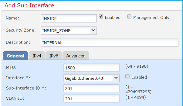
Configure subinterface G0/0.201 and interface G0/1 as per these requirements:
| Interface |
G0/0.201 |
G0/1 |
| Name |
INSIDE |
OUTSIDE |
| Security Zone |
INSIDE_ZONE |
OUTSIDE_ZONE |
| Description |
INTERNAL |
EXTERNAL |
| Sub interface ID |
201 |
- |
| VLAN ID |
201 |
- |
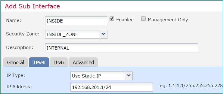
| IPv4 |
192.168.201.1/24 |
192.168.202.1/24 |
| Duplex/Speed |
Auto |
Auto |
Solution
Step 1. Configure the Logical Interface
Navigate to Devices > Device Management, select the appropriate device and select the Edit icon:

Select Add Interfaces > Sub Interface:

Configure the subinterface settings as per requirements:
Interface IP settings:
Under the physical interface (GigabitEthernet0/0) specify the Duplex and Speed settings:

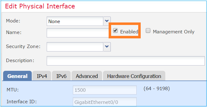
Enable the physical interface (G0/0 in this case):
Step 2. Configure the Physical Interface
Edit the GigabitEthernet0/1 physical interface as per requirements:
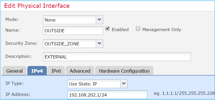
- For Routed interface the Mode is: None
- The Name is equivalent to the ASA interface nameif
- On FTD all interfaces have security level = 0
- same-security-traffic is not applicable on FTD. Traffic between FTD interfaces (inter) and (intra) is allowed by default
Select Save and Deploy.
Verification
From the FMC GUI:
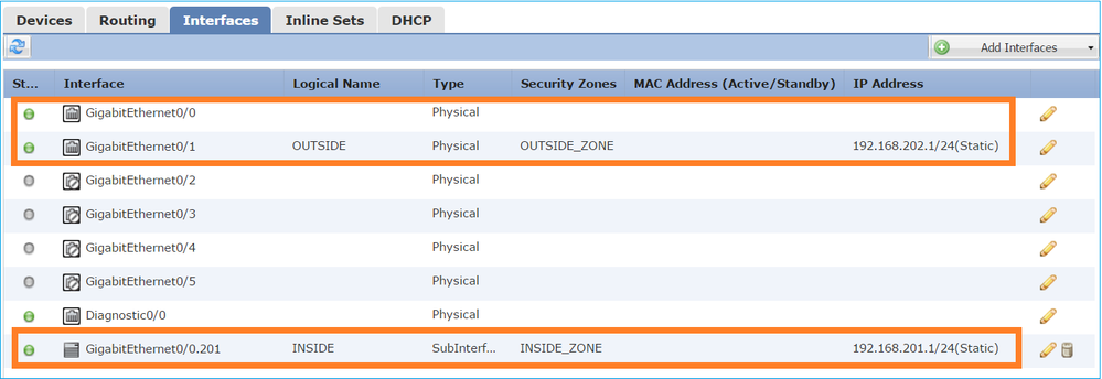
From the FTD CLI:
> show interface ip brief
Interface                  IP-Address      OK? Method Status                Protocol
GigabitEthernet0/0         unassigned      YES unset  up                    up
GigabitEthernet0/0.201     192.168.201.1   YES manual up                    up
GigabitEthernet0/1         192.168.202.1   YES manual up                    up
GigabitEthernet0/2         unassigned      YES unset  administratively down down
GigabitEthernet0/3         unassigned      YES unset  administratively down down
GigabitEthernet0/4         unassigned      YES unset  administratively down down
GigabitEthernet0/5         unassigned      YES unset  administratively down down
Internal-Control0/0        127.0.1.1       YES unset  up                    up
Internal-Data0/0           unassigned      YES unset  up                    up
Internal-Data0/1           unassigned      YES unset  up                    up
Internal-Data0/2           169.254.1.1     YES unset  up                    up
Management0/0              unassigned      YES unset  up                    up
> show ip
System IP Addresses:
Interface                Name                   IP address      Subnet mask     Method
GigabitEthernet0/0.201   INSIDE                 192.168.201.1   255.255.255.0   manual
GigabitEthernet0/1       OUTSIDE                192.168.202.1   255.255.255.0   manual
Current IP Addresses:
Interface                Name                   IP address      Subnet mask     Method
GigabitEthernet0/0.201   INSIDE                 192.168.201.1   255.255.255.0   manual
GigabitEthernet0/1       OUTSIDE                192.168.202.1   255.255.255.0   manual
FMC GUI and FTD CLI correlation:

> show interface g0/0.201
Interface GigabitEthernet0/0.201 "INSIDE", is up, line protocol is up
  Hardware is i82574L rev00, BW 1000 Mbps, DLY 10 usec
        VLAN identifier 201
        Description: INTERNAL
        MAC address a89d.21ce.fdea, MTU 1500
        IP address 192.168.201.1, subnet mask 255.255.255.0
  Traffic Statistics for "INSIDE":
        1 packets input, 28 bytes
        1 packets output, 28 bytes
        0 packets dropped
> show interface g0/1
Interface GigabitEthernet0/1 "OUTSIDE", is up, line protocol is up
  Hardware is i82574L rev00, BW 1000 Mbps, DLY 10 usec
        Auto-Duplex(Full-duplex), Auto-Speed(1000 Mbps)
        Input flow control is unsupported, output flow control is off
        Description: EXTERNAL
        MAC address a89d.21ce.fde7, MTU 1500
        IP address 192.168.202.1, subnet mask 255.255.255.0
        0 packets input, 0 bytes, 0 no buffer
        Received 0 broadcasts, 0 runts, 0 giants
        0 input errors, 0 CRC, 0 frame, 0 overrun, 0 ignored, 0 abort
        0 pause input, 0 resume input
        0 L2 decode drops
        1 packets output, 64 bytes, 0 underruns
        0 pause output, 0 resume output
        0 output errors, 0 collisions, 12 interface resets
        0 late collisions, 0 deferred
        0 input reset drops, 0 output reset drops
        input queue (blocks free curr/low): hardware (511/511)
        output queue (blocks free curr/low): hardware (511/511)
  Traffic Statistics for "OUTSIDE":
        0 packets input, 0 bytes
        0 packets output, 0 bytes
        0 packets dropped
      1 minute input rate 0 pkts/sec,  0 bytes/sec
      1 minute output rate 0 pkts/sec,  0 bytes/sec
      1 minute drop rate, 0 pkts/sec
      5 minute input rate 0 pkts/sec,  0 bytes/sec
      5 minute output rate 0 pkts/sec,  0 bytes/sec
      5 minute drop rate, 0 pkts/sec
>
FTD Routed Interface Operation
Verify the FTD packet flow when Routed interfaces are in use.
Solution
FTD Architectural overview
A high-level overview of the FTD data plane:

This picture shows some of the checks that occur within each engine:

Key points
- The bottom checks correspond to the FTD LINA engine Data Path
- The checks inside the blue box correspond to the FTD Snort engine instance
FTD Routed Interface Overview
- Available only in Routed Deployment
- Traditional L3 firewall deployment
- One or more physical or logical (VLAN) routable interfaces
- Allows features like NAT or Dynamic Routing protocols to be configured
- Packets are forwarded based on Route Lookup and next hop is resolved based on ARP Lookup
- Actual traffic can be dropped
- Full LINA engine checks are applied along with full Snort engine checks
The last point can be visualized accordingly:

Verify
Trace a Packet on FTD Routed Interface
Network Diagram

Use packet-tracer with the these parameters to see the applied policies:
|
Input interface
|
INSIDE
|
|
Protocol/Service
|
TCP port 80
|
|
Source IP
|
192.168.201.100
|
|
Destination IP
|
192.168.202.100
|
Solution
When a routed interface is used the packet is processed in a similar way to a classic ASA Routed interface. Checks like Route Lookup, Modular Policy Framework (MPF), NAT, ARP lookup etc take place in the LINA engine Data Path. Additionally, if the Access Control Policy requires so, the packet is inspected by the Snort engine (one of the Snort instances) where a verdict is generated and returned back to the LINA engine:
> packet-tracer input INSIDE tcp 192.168.201.100 11111 192.168.202.100 80

Phase: 1
Type: ROUTE-LOOKUP
Subtype: Resolve Egress Interface
Result: ALLOW
Config:
Additional Information:
found next-hop 192.168.202.100 using egress ifc  OUTSIDE

Phase: 2
Type: ACCESS-LIST
Subtype: log
Result: ALLOW
Config:
access-group CSM_FW_ACL_ global
access-list CSM_FW_ACL_ advanced permit ip any any rule-id 268437505
access-list CSM_FW_ACL_ remark rule-id 268437505: ACCESS POLICY: FTD5512 - Default/1
access-list CSM_FW_ACL_ remark rule-id 268437505: L4 RULE: DEFAULT ACTION RULE
Additional Information:
 This packet will be sent to snort for additional processing where a verdict will be reached

Phase: 3
Type: CONN-SETTINGS
Subtype:
Result: ALLOW
Config:
class-map class-default
 match any
policy-map global_policy
 class class-default
  set connection advanced-options UM_STATIC_TCP_MAP
service-policy global_policy global
Additional Information:

Phase: 4
Type: NAT
Subtype: per-session
Result: ALLOW
Config:
Additional Information:

Phase: 5
Type: IP-OPTIONS
Subtype:
Result: ALLOW
Config:
Additional Information:

Phase: 6
Type: NAT
Subtype: per-session
Result: ALLOW
Config:
Additional Information:

Phase: 7
Type: IP-OPTIONS
Subtype:
Result: ALLOW
Config:
Additional Information:

Phase: 8
Type: FLOW-CREATION
Subtype:
Result: ALLOW
Config:
Additional Information:
New flow created with id 11336, packet dispatched to next module

Result:
input-interface: INSIDE
input-status: up
input-line-status: up
output-interface: OUTSIDE
output-status: up
output-line-status: up
Action: allow

>
Note: In phase 4 the packet is checked against a TCP map called UM_STATIC_TCP_MAP. This is the default TCP Map on FTD.
firepower# show run all tcp-map
!
tcp-map UM_STATIC_TCP_MAP
  no check-retransmission
  no checksum-verification
  exceed-mss allow
  queue-limit 0 timeout 4
  reserved-bits allow
  syn-data allow
  synack-data drop
  invalid-ack drop
  seq-past-window drop
  tcp-options range 6 7 allow
  tcp-options range 9 18 allow
  tcp-options range 20 255 allow
  tcp-options selective-ack allow
  tcp-options timestamp allow
  tcp-options window-scale allow
  tcp-options mss allow
  tcp-options md5 clear
  ttl-evasion-protection
  urgent-flag allow
  window-variation allow-connection
!
>
Related Information


 Feedback